
Owner's Manual
Page 1
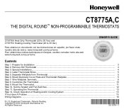
... the System and Fan Switches ...12 Step 11. Registered Trademark • Patents Pending Copyright © 2004 Honeywell International Inc. CT8775A,C THE DIGITAL ROUND™ NON-PROGRAMMABLE THERMOSTATS CT8775A Heat Only Thermostat (20 to 30 Vac) and CT8775C Heating-Cooling Thermostat (20 to 30 Vac) Para obtener un documento con las instrucciones en español, por favor...
... the System and Fan Switches ...12 Step 11. Registered Trademark • Patents Pending Copyright © 2004 Honeywell International Inc. CT8775A,C THE DIGITAL ROUND™ NON-PROGRAMMABLE THERMOSTATS CT8775A Heat Only Thermostat (20 to 30 Vac) and CT8775C Heating-Cooling Thermostat (20 to 30 Vac) Para obtener un documento con las instrucciones en español, por favor...
Owner's Manual
Page 3
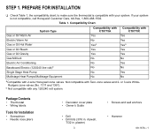
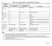
...PREPARE FOR INSTALLATION ❑ Check Table 1, the compatibility chart, to make sure the thermostat is not compatible, call Honeywell Customer Care, toll-free, 1-800-468-1502. If your system. b Not compatible with 2-wire Honeywell zone valves. Compatibility Chart. System Type Gas or Oil Warm Air Electric Warm Air Gas... Electric (120/240 line volt)b Single Stage Heat Pump Multistage Heat Pumps/Multistage Equipment Compatibility with CT8775A Yes No Yesa Yes Yes No No No No No Compatibility with CT8775C Yes Yes Yesa Yes Yes No Yes No Yes No aCompatible with any 120/240 volt system...
...PREPARE FOR INSTALLATION ❑ Check Table 1, the compatibility chart, to make sure the thermostat is not compatible, call Honeywell Customer Care, toll-free, 1-800-468-1502. If your system. b Not compatible with 2-wire Honeywell zone valves. Compatibility Chart. System Type Gas or Oil Warm Air Electric Warm Air Gas... Electric (120/240 line volt)b Single Stage Heat Pump Multistage Heat Pumps/Multistage Equipment Compatibility with CT8775A Yes No Yesa Yes Yes No No No No No Compatibility with CT8775C Yes Yes Yesa Yes Yes No Yes No Yes No aCompatible with any 120/240 volt system...
Owner's Manual
Page 5
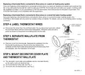
... thermostat by setting the thermostat fan switch to ON, the CT8775C Thermostat will only work with the installation at the right. MOUNT DECORATOR COVER PLATE AND THERMOSTAT WALLPLATE ❑ The decorator cover plate and wallplate can be mounted directly on the top between the wallplate and the thermostat and pulling the thermostat away from thermostat. If you purchased a CT8775A thermostat...
... thermostat by setting the thermostat fan switch to ON, the CT8775C Thermostat will only work with the installation at the right. MOUNT DECORATOR COVER PLATE AND THERMOSTAT WALLPLATE ❑ The decorator cover plate and wallplate can be mounted directly on the top between the wallplate and the thermostat and pulling the thermostat away from thermostat. If you purchased a CT8775A thermostat...
Owner's Manual
Page 8
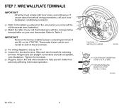
G ❑ Refer to the labels you placed on the wires when you removed the Y old thermostat (see illustration). ❑ Match the letter of your old thermostat wire with the corresponding W terminal letter on the CT8775C Thermostat if wires will be connected to both acceptable, (see pp 16-17. ❑ Loosen the terminal screws. Refer to...
G ❑ Refer to the labels you placed on the wires when you removed the Y old thermostat (see illustration). ❑ Match the letter of your old thermostat wire with the corresponding W terminal letter on the CT8775C Thermostat if wires will be connected to both acceptable, (see pp 16-17. ❑ Loosen the terminal screws. Refer to...
Owner's Manual
Page 9
...connect Rh to R and R to Rc. 2. Do not connect both Rh and R terminals on the old thermostat, remove jumper between R and Rc on the new thermostat, remove jumper between R and Rc. 3. W - - - - installation. Tape off wire with electri-.... (Single stage heat pump only). Call 1-800468-1502. If wires were connected to Terminals Connect To Terminals on CT8775A on Old and New Thermostats. Table 2. Terminal Designations on CT8775C R R (see Note 2) Power Description - Terminal on Old Thermostat R Rh (see Note 1) 4 V Rc R (see Note 1) W, W1, H Y, Y1, M G, F O B (see ...
...connect Rh to R and R to Rc. 2. Do not connect both Rh and R terminals on the old thermostat, remove jumper between R and Rc on the new thermostat, remove jumper between R and Rc. 3. W - - - - installation. Tape off wire with electri-.... (Single stage heat pump only). Call 1-800468-1502. If wires were connected to Terminals Connect To Terminals on CT8775A on Old and New Thermostats. Table 2. Terminal Designations on CT8775C R R (see Note 2) Power Description - Terminal on Old Thermostat R Rh (see Note 1) 4 V Rc R (see Note 1) W, W1, H Y, Y1, M G, F O B (see ...
Owner's Manual
Page 10
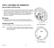
...a heat pump, set according to turn on the back of the thermostat. See Fig. 4. See Table 3. STEP 8. Set Heat Cycle Rate ❑ Use DIP switches 1 and 2 to E. NOTE: The CT8775A,C Thermostats will provide optimal temperature control if DIP switches 1 and 2 are set... the switch to set in the F position. FUEL SWITCH M19497 Fig. 3. This is connected. The E setting allows the fan to your particular heating system. Fuel switch. CUSTOMIZE THE THERMOSTAT Set Fuel Switch (CT8775C ...
...a heat pump, set according to turn on the back of the thermostat. See Fig. 4. See Table 3. STEP 8. Set Heat Cycle Rate ❑ Use DIP switches 1 and 2 to E. NOTE: The CT8775A,C Thermostats will provide optimal temperature control if DIP switches 1 and 2 are set... the switch to set in the F position. FUEL SWITCH M19497 Fig. 3. This is connected. The E setting allows the fan to your particular heating system. Fuel switch. CUSTOMIZE THE THERMOSTAT Set Fuel Switch (CT8775C ...
Owner's Manual
Page 12
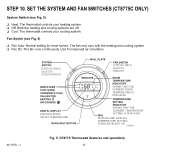
...) System Switch (see Fig. 5) ❑ Fan Auto: Normal setting for improved air circulation. 69-1676-1 (CT8775C ONLY) SELECTS COOL/OFF/HEAT (CT8775C ONLY) SELECTS ON/AUTO ROOM SET SHOWS THAT THE CURRENT ROOM TEMPERATURE IS DISPLAYED DISPLAYS ROOM OR SET TEMPERATURE SHOWS ... fan only runs with the heating and cooling system. ❑ Fan On: The fan runs continuously. CT8775 Thermostat (features and operation). 12 STEP 10. Fan Switch (see Fig. 5) ❑ Heat: The thermostat controls your heating system. ❑ Off: Both the heating and cooling systems are off. ❑ Cool:...
...) System Switch (see Fig. 5) ❑ Fan Auto: Normal setting for improved air circulation. 69-1676-1 (CT8775C ONLY) SELECTS COOL/OFF/HEAT (CT8775C ONLY) SELECTS ON/AUTO ROOM SET SHOWS THAT THE CURRENT ROOM TEMPERATURE IS DISPLAYED DISPLAYS ROOM OR SET TEMPERATURE SHOWS ... fan only runs with the heating and cooling system. ❑ Fan On: The fan runs continuously. CT8775 Thermostat (features and operation). 12 STEP 10. Fan Switch (see Fig. 5) ❑ Heat: The thermostat controls your heating system. ❑ Off: Both the heating and cooling systems are off. ❑ Cool:...
Owner's Manual
Page 13
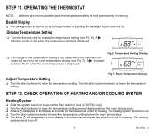
.... Room Temperature Display. ROOM SET ❑ If a change to the temperature setting is held permanently in the display to indicate the thermostat has ended the call for heating. Temperature Setting Display. STEP 11. CHECK OPERATION OF HEATING AND/OR COOLING SYSTEM Heating System ❑... Slide the system switch to Heat and the Fan switch to Auto (CT8775C only). ❑ Turn the dial clockwise to raise the temperature setting several degrees above the room temperature. ❑ A flame will disappear...
.... Room Temperature Display. ROOM SET ❑ If a change to the temperature setting is held permanently in the display to indicate the thermostat has ended the call for heating. Temperature Setting Display. STEP 11. CHECK OPERATION OF HEATING AND/OR COOLING SYSTEM Heating System ❑... Slide the system switch to Heat and the Fan switch to Auto (CT8775C only). ❑ Turn the dial clockwise to raise the temperature setting several degrees above the room temperature. ❑ A flame will disappear...
Owner's Manual
Page 14
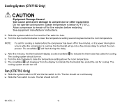
...minutes, or if a power interruption occurs while the compressor is running, the thermostat will display a solid snowflake to indicate the thermostat has ended the call for cooling is below the room temperature. Fan (CT8775C Only) ❑ Slide the system switch to Off and the fan switch... to compressor or other equipment. Cooling System (CT8775C Only) CAUTION Equipment Damage Hazard. The ...
...minutes, or if a power interruption occurs while the compressor is running, the thermostat will display a solid snowflake to indicate the thermostat has ended the call for cooling is below the room temperature. Fan (CT8775C Only) ❑ Slide the system switch to Off and the fan switch... to compressor or other equipment. Cooling System (CT8775C Only) CAUTION Equipment Damage Hazard. The ...
Owner's Manual
Page 15
...system (example: Gas, oil, or electric; Before calling, please have the following information available: • Thermostat model number. (Located on . • Set the system switch to Cool (CT8775C only). • Make sure the temperature setting is below model number). • Type of wires connected to...Wait five minutes for this has been checked, contact your local heating and cooling contractor. For additional information, go to www.honeywell.com/yourhome or call Honeywell Customer Care, toll free, at the equipment is in the On position, and set the heating higher 40 to 90&#...
...system (example: Gas, oil, or electric; Before calling, please have the following information available: • Thermostat model number. (Located on . • Set the system switch to Cool (CT8775C only). • Make sure the temperature setting is below model number). • Type of wires connected to...Wait five minutes for this has been checked, contact your local heating and cooling contractor. For additional information, go to www.honeywell.com/yourhome or call Honeywell Customer Care, toll free, at the equipment is in the On position, and set the heating higher 40 to 90&#...


