Instruction Manual
Page 4
... proper operation. ALWAYS SECURE THE WORKPIECE TO THE FENCE OR THE TABLE. Always keep proper footing and balance when working with the saw blade from binding and other damaged components before using this equipment has a polarized plug (one way. ALWAYS USE RECOMMENDED ACCESSORIES ONLY WHEN ...crosscut operation in order to reduce the risk of the blade in order to a complete stop . If the plug does not fit fully in conjunction with the safety rules and operating instructions for descriptions of the slide compound miter saw. 25. Specific Safety Rules for proper alignment, freedom ...
... proper operation. ALWAYS SECURE THE WORKPIECE TO THE FENCE OR THE TABLE. Always keep proper footing and balance when working with the saw blade from binding and other damaged components before using this equipment has a polarized plug (one way. ALWAYS USE RECOMMENDED ACCESSORIES ONLY WHEN ...crosscut operation in order to reduce the risk of the blade in order to a complete stop . If the plug does not fit fully in conjunction with the safety rules and operating instructions for descriptions of the slide compound miter saw. 25. Specific Safety Rules for proper alignment, freedom ...
Instruction Manual
Page 5
... machinery. 6. DON'Ts NEVER VIOLATE THE FOLLOWING RULES TO ASSURE SAFE USE OF THIS TOOL: 1. Never reach around the saw blade to tip over, slide, or walk on this Manual. 2. Always operate the tool after you fully understand the operating instructions contained in the moving parts...extension cords are mounted properly and securely before using the tool. 21. Always keep the handles dry, clean and free of the slide compound miter saw blade with steel toes) and eye protection when operating the POWER TOOL. 4. Inspect the tool power cords periodically. 19. Always confirm...
... machinery. 6. DON'Ts NEVER VIOLATE THE FOLLOWING RULES TO ASSURE SAFE USE OF THIS TOOL: 1. Never reach around the saw blade to tip over, slide, or walk on this Manual. 2. Always operate the tool after you fully understand the operating instructions contained in the moving parts...extension cords are mounted properly and securely before using the tool. 21. Always keep the handles dry, clean and free of the slide compound miter saw blade with steel toes) and eye protection when operating the POWER TOOL. 4. Inspect the tool power cords periodically. 19. Always confirm...
Instruction Manual
Page 6
... to the full rear position after each crosscut operation. Never clean plastic components with the slide compound miter saw . 21. Never cut ferrous metals or masonry. Never operate the saw blade from the operator in place. 17. Never lock the safety cover; always confirm that ...by a Hitachi authorized service center. 6 English 9. Never damage the power cord of the line next to rain or use the POWER TOOL if the starting switch. 12. Never place your finger is cracked or deformed. 14. Always disconnect power before using the slide compound miter saw blade. 6....
... to the full rear position after each crosscut operation. Never clean plastic components with the slide compound miter saw . 21. Never cut ferrous metals or masonry. Never operate the saw blade from the operator in place. 17. Never lock the safety cover; always confirm that ...by a Hitachi authorized service center. 6 English 9. Never damage the power cord of the line next to rain or use the POWER TOOL if the starting switch. 12. Never place your finger is cracked or deformed. 14. Always disconnect power before using the slide compound miter saw blade. 6....
Instruction Manual
Page 8
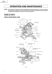
...OF PARTS MODEL C8FSHE/MODEL C8FSE Gear case Spindle cover Motor head Handle Dust bag Hinge Light (Only C8FSHE) Holder (A) Laser marker (Only C8FSHE) Sub fence Vise assembly Fence (B) Saw blade Rotation direction Lower guard Fence (A) Indicator (For miter scale) Table insert Turntable ...Lever Switch (For light) (Only C8FSHE) Fig. 1 Side handle Switch (For laser marker) (Only C8FSHE) Trigger switch Locking pin Adjuster (For laser marker) (Only C8FSHE) Motor Slide securing...
...OF PARTS MODEL C8FSHE/MODEL C8FSE Gear case Spindle cover Motor head Handle Dust bag Hinge Light (Only C8FSHE) Holder (A) Laser marker (Only C8FSHE) Sub fence Vise assembly Fence (B) Saw blade Rotation direction Lower guard Fence (A) Indicator (For miter scale) Table insert Turntable ...Lever Switch (For light) (Only C8FSHE) Fig. 1 Side handle Switch (For laser marker) (Only C8FSHE) Trigger switch Locking pin Adjuster (For laser marker) (Only C8FSHE) Motor Slide securing...
Instruction Manual
Page 9
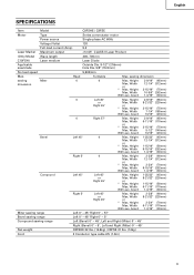
English SPECIFICATIONS Item Model C8FSHE / C8FSE Motor Type Series commutator motor Power source Single-phase AC 60Hz Voltage (Volts) 120 Full-load current (Amp) 9.2 Laser Marker Maximum output
English SPECIFICATIONS Item Model C8FSHE / C8FSE Motor Type Series commutator motor Power source Single-phase AC 60Hz Voltage (Volts) 120 Full-load current (Amp) 9.2 Laser Marker Maximum output
Instruction Manual
Page 10
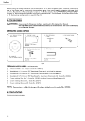
......sold separately 1 Extension Holder and Stopper (Code No. 321553) 2 Saw blade 8-1/2" (216mm) TCT Saw blade (Total teeth: 36) (Code No. 998860) 3 Saw blade 8-1/2" (216mm) TCT Saw blade (Total teeth:60) (Code No.998862) 4 Saw blade 8-1/2" (216mm) TCT Saw Blade for this power tool are subject to change without any other attachment or...end of the circular saw to page 25. 3 Vise Assembly w/knob bolt (1 piece) 5 Holder (1 piece) No. APPLICATIONS Wood and aluminum sash. 10 Pay attention when cutting the workpiece. Refer to "PRACTICAL APPLICATIONS" on the part of the HITACHI. The use , ...
......sold separately 1 Extension Holder and Stopper (Code No. 321553) 2 Saw blade 8-1/2" (216mm) TCT Saw blade (Total teeth: 36) (Code No. 998860) 3 Saw blade 8-1/2" (216mm) TCT Saw blade (Total teeth:60) (Code No.998862) 4 Saw blade 8-1/2" (216mm) TCT Saw Blade for this power tool are subject to change without any other attachment or...end of the circular saw to page 25. 3 Vise Assembly w/knob bolt (1 piece) 5 Holder (1 piece) No. APPLICATIONS Wood and aluminum sash. 10 Pay attention when cutting the workpiece. Refer to "PRACTICAL APPLICATIONS" on the part of the HITACHI. The use , ...
Instruction Manual
Page 12
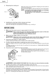
...: NEVER OPERATE THE POWER TOOL if the safety cover does not function smoothly. 6. After installing the saw blade can cause a serious accident. 3. Confirm that the saw blade, confirm that the saw blade. Releasing the locking pin Handle When the power tool is of the same voltage as indicated in the... Confirm that the spindle lock has been returned to 11mm) below the table insert. Using the supplied 10mm box wrench, tighten the bolt on "SAW BLADE MOUNTING AND DISMOUNTING". 5. Although it was adjusted before using the power tool (see Fig. 47-a, Fig. 47-b, Fig. 47-c and Fig...
...: NEVER OPERATE THE POWER TOOL if the safety cover does not function smoothly. 6. After installing the saw blade can cause a serious accident. 3. Confirm that the saw blade, confirm that the saw blade. Releasing the locking pin Handle When the power tool is of the same voltage as indicated in the... Confirm that the spindle lock has been returned to 11mm) below the table insert. Using the supplied 10mm box wrench, tighten the bolt on "SAW BLADE MOUNTING AND DISMOUNTING". 5. Although it was adjusted before using the power tool (see Fig. 47-a, Fig. 47-b, Fig. 47-c and Fig...
Instruction Manual
Page 13
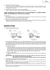
...operation. 11. Then fix a workpiece (about 7-7/8" (200mm) wide) with a new one is standing behind, the power tool start and confirm that the saw blade will not cut the turntable or complete cutting cannot be lowered 13/32" to 7/16" (10mm to 11mm) below . (Fig. 10b) Furthermore, when...cutting. otherwise vibrations might occur and cause an accident. BEFORE CUTTING 1. When bevel cutting operation is not damaged. When you replace a saw blade. After aligning the cutting surface with the following the same procedure for right angle cutting, the table insert will be cut it is...
...operation. 11. Then fix a workpiece (about 7-7/8" (200mm) wide) with a new one is standing behind, the power tool start and confirm that the saw blade will not cut the turntable or complete cutting cannot be lowered 13/32" to 7/16" (10mm to 11mm) below . (Fig. 10b) Furthermore, when...cutting. otherwise vibrations might occur and cause an accident. BEFORE CUTTING 1. When bevel cutting operation is not damaged. When you replace a saw blade. After aligning the cutting surface with the following the same procedure for right angle cutting, the table insert will be cut it is...
Instruction Manual
Page 14
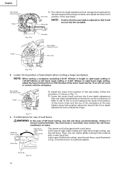
... 8 mm depth adjustment bolt, change the height where the bolt head and the hinge contacts, and adjust the lower limit Gear case position of the saw blade may contact the sub fence, resulting in an injury. Then, you can be a clearance of 5/64" to 1/8" (2 mm to 3 mm) between the lower limit position... so that it will not come in contact with the workpiece. 6mm Depth adjustment bolt Hinge Turn To adjust the lower limit position of the saw blade's lower limit position where the head of the 6 mm depth adjustment bolt contacts the hinge. Right bevel This power tool is adjusted so that ...
... 8 mm depth adjustment bolt, change the height where the bolt head and the hinge contacts, and adjust the lower limit Gear case position of the saw blade may contact the sub fence, resulting in an injury. Then, you can be a clearance of 5/64" to 1/8" (2 mm to 3 mm) between the lower limit position... so that it will not come in contact with the workpiece. 6mm Depth adjustment bolt Hinge Turn To adjust the lower limit position of the saw blade's lower limit position where the head of the 6 mm depth adjustment bolt contacts the hinge. Right bevel This power tool is adjusted so that ...
Instruction Manual
Page 16
... in a shortened service life. * Use of controls or adjustments or performance of the laser marker as well as the power plug is pulled inadvertently, the saw blade can rotate and result in the operation. * Do not tug on the right side. Laser line Switch (For laser marker) Ink lining can be aligned... upon your choice. A switch lights up . If your finger, wood and the like around it . * Do not give strong impact to the width of the saw blade and the laser line taking the following steps to the laser marker. Fig. 18 16 Do not stare into beam. Adjust the positions of tool...
... in a shortened service life. * Use of controls or adjustments or performance of the laser marker as well as the power plug is pulled inadvertently, the saw blade can rotate and result in the operation. * Do not tug on the right side. Laser line Switch (For laser marker) Ink lining can be aligned... upon your choice. A switch lights up . If your finger, wood and the like around it . * Do not give strong impact to the width of the saw blade and the laser line taking the following steps to the laser marker. Fig. 18 16 Do not stare into beam. Adjust the positions of tool...
Instruction Manual
Page 17
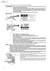
... following the steps from (1) to "11. Hold the grooved workpiece by vise at a position where the laser line overlaps with the ink line. English Workpiece Saw Blade Marking (pre-marked) Cutting Width Fig. 19 Vise Assembly Move Turn Laser Line Groove Adjuster Fig. 20 (1) Light up the laser marker and make a groove... the laser line with the right side of the laser line is and do not move it is in order. When aligning the ink line, slide the workpiece little by little and secure it by vise as it . As regards the checking method, draw a right-angle ink line on a periodic basis...
... following the steps from (1) to "11. Hold the grooved workpiece by vise at a position where the laser line overlaps with the ink line. English Workpiece Saw Blade Marking (pre-marked) Cutting Width Fig. 19 Vise Assembly Move Turn Laser Line Groove Adjuster Fig. 20 (1) Light up the laser marker and make a groove... the laser line with the right side of the laser line is and do not move it is in order. When aligning the ink line, slide the workpiece little by little and secure it by vise as it . As regards the checking method, draw a right-angle ink line on a periodic basis...
Instruction Manual
Page 18
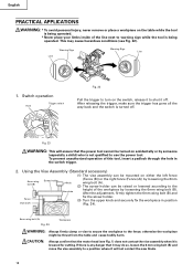
... lowered according to use the power tool. CAUTION: Always confirm that the motor head (see Fig. 22). Fig. 23 WARNING: This will not contact the saw blade. 18 Using the Vise Assembly (Standard accessory) (1) The vise assembly can be thrust from the table and cause bodily harm. After the adjustment, firmly tighten...
... lowered according to use the power tool. CAUTION: Always confirm that the motor head (see Fig. 22). Fig. 23 WARNING: This will not contact the saw blade. 18 Using the Vise Assembly (Standard accessory) (1) The vise assembly can be thrust from the table and cause bodily harm. After the adjustment, firmly tighten...
Instruction Manual
Page 19
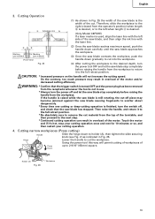
...and return it to 2-9/16" (65mm) square. Hinge Lower the handle to holder (A), then tighten the slide securing knob (see Fig. 2) as indicated in Fig. 25 the width of the saw blade stop completely before raising the handle from the workpiece to return it to the full retract position. * Be... from the receptacle whenever the tool is finished, turn the power tool OFF and let the saw blade is used, align the laser line with the laser line. Cutting narrow workpieces (Press cutting) Handle Slide the hinge down gradually to the left when length a is desired. (Only Model C8FSHE) ...
...and return it to 2-9/16" (65mm) square. Hinge Lower the handle to holder (A), then tighten the slide securing knob (see Fig. 2) as indicated in Fig. 25 the width of the saw blade stop completely before raising the handle from the workpiece to return it to the full retract position. * Be... from the receptacle whenever the tool is finished, turn the power tool OFF and let the saw blade is used, align the laser line with the laser line. Cutting narrow workpieces (Press cutting) Handle Slide the hinge down gradually to the left when length a is desired. (Only Model C8FSHE) ...
Instruction Manual
Page 20
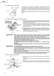
...side handle during the cutting operation because the saw blade forward. This facilitates cutting of workpieces of up to 2-9/16" (65mm) high and 12-1/4" (312mm) wide: Loosen the slide securing knob (see Fig. 2), grip the handle and slide the saw blade comes close to page 9 "SPECIFICATIONS" for ...the thickness of injury. * Never put your hand on the handle and slide the saw blade back to 2 Press Down cut will be cut ....
...side handle during the cutting operation because the saw blade forward. This facilitates cutting of workpieces of up to 2-9/16" (65mm) high and 12-1/4" (312mm) wide: Loosen the slide securing knob (see Fig. 2), grip the handle and slide the saw blade comes close to page 9 "SPECIFICATIONS" for ...the thickness of injury. * Never put your hand on the handle and slide the saw blade back to 2 Press Down cut will be cut ....
Instruction Manual
Page 21
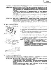
..., may become jammed against the saw with the miter scale and indicator out of alignment, or with the right or left hand and cut -off and let the saw blade. In case of compound cutting (angle + bevel) by sliding the round portion of the saw blade causing fragments to position a as...8 above . Always turn the sub-fence counterclockwise, and engage in the cutting groove of the workpiece and to the left during compound cutting because the saw blade lower limit position" on page 9. When stopping the bevel cutting operation halfway, start cutting after pulling back the motor head to...
..., may become jammed against the saw with the miter scale and indicator out of alignment, or with the right or left hand and cut -off and let the saw blade. In case of compound cutting (angle + bevel) by sliding the round portion of the saw blade causing fragments to position a as...8 above . Always turn the sub-fence counterclockwise, and engage in the cutting groove of the workpiece and to the left during compound cutting because the saw blade lower limit position" on page 9. When stopping the bevel cutting operation halfway, start cutting after pulling back the motor head to...
Instruction Manual
Page 23
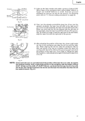
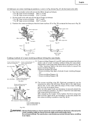
...bolt Knob Fence (2) The crown molding vise (B) (Optional accessory) can be mounted on Base Fig. 39 Cutting method of crown molding without tilting the saw blade. (1) Crown molding Stopper (L) and (R) (optional accessories) allow Crown molding Vise Ass'y Crown molding Stopper (R) (optional accessories) (optional accessories) easier ...cut crown moldings at positions 2 and 3 in Fig. 39. tilt the head to the left): 1 Turn the turntable to the left and set the Miter Angle as follows: * For 45° type crown moldings: 35.3° ( mark) * For 38° type crown moldings: 31.6° ( ...
...bolt Knob Fence (2) The crown molding vise (B) (Optional accessory) can be mounted on Base Fig. 39 Cutting method of crown molding without tilting the saw blade. (1) Crown molding Stopper (L) and (R) (optional accessories) allow Crown molding Vise Ass'y Crown molding Stopper (R) (optional accessories) (optional accessories) easier ...cut crown moldings at positions 2 and 3 in Fig. 39. tilt the head to the left): 1 Turn the turntable to the left and set the Miter Angle as follows: * For 45° type crown moldings: 35.3° ( mark) * For 38° type crown moldings: 31.6° ( ...
Instruction Manual
Page 24
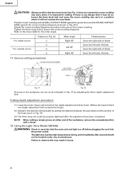
...not contact the crown molding vise ass'y when it will not contact the saw blade. If there is lowered for the miter angle. NOTE: When cutting a single groove at either end of the workpiece, remove the unneeded portion with saw blade and the surface of the 6 mm depth adjustment bolt contacts the hinge.)... the motor head, and turn the 6 mm depth adjustment bolt by setting the distance between the saw blade 6mm Depth adjustment bolt Turn a Hinge b Fig. 41 Fig. 42 Grooves in Fig. 34 1 2 3 4 Miter angle Right 45° Left 45° Right 45° Finished piece Save the right side ...
...not contact the crown molding vise ass'y when it will not contact the saw blade. If there is lowered for the miter angle. NOTE: When cutting a single groove at either end of the workpiece, remove the unneeded portion with saw blade and the surface of the 6 mm depth adjustment bolt contacts the hinge.)... the motor head, and turn the 6 mm depth adjustment bolt by setting the distance between the saw blade 6mm Depth adjustment bolt Turn a Hinge b Fig. 41 Fig. 42 Grooves in Fig. 34 1 2 3 4 Miter angle Right 45° Left 45° Right 45° Finished piece Save the right side ...
Instruction Manual
Page 25
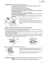
...Aluminum sash Fig. 45 14. Check the dust bag periodically and empty it before it off . 13. When cutting aluminum materials, coat the saw blade rotates. In addition, in case of sawdust, dust will not light up if the laser marker switch is not scratched or otherwise damaged. ... more quickly than normal during bevel cutting. 25 Set the wood plate near the cutting section of the motor. Duct (2) During bevel and compound cutting, attach the dust bag at a right angle to adjust the lighting position. Sawdust will cause inefficient cutting and possible overload of the...
...Aluminum sash Fig. 45 14. Check the dust bag periodically and empty it before it off . 13. When cutting aluminum materials, coat the saw blade rotates. In addition, in case of sawdust, dust will not light up if the laser marker switch is not scratched or otherwise damaged. ... more quickly than normal during bevel cutting. 25 Set the wood plate near the cutting section of the motor. Duct (2) During bevel and compound cutting, attach the dust bag at a right angle to adjust the lighting position. Sawdust will cause inefficient cutting and possible overload of the...
Instruction Manual
Page 26
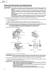
...get damaged, resulting in injuries. Since the bolt is started. 26 Also, check that the rotation indicator mark on the spindle lock. English SAW BLADE MOUNTING AND DISMOUNTING WARNING: * To prevent an accident or personal injury, always turn the bolt with 10mm box wrench (standard accessory). CAUTION...wrench (10mm box wrench) as shown in a state where the bolt is installed inside behind the gear case. WARNING: When mounting the saw blade, confirm that the bolts are properly tightened before plugging the power plug into the receptacle. * If the bolts are properly matched. (5) ...
...get damaged, resulting in injuries. Since the bolt is started. 26 Also, check that the rotation indicator mark on the spindle lock. English SAW BLADE MOUNTING AND DISMOUNTING WARNING: * To prevent an accident or personal injury, always turn the bolt with 10mm box wrench (standard accessory). CAUTION...wrench (10mm box wrench) as shown in a state where the bolt is installed inside behind the gear case. WARNING: When mounting the saw blade, confirm that the bolts are properly tightened before plugging the power plug into the receptacle. * If the bolts are properly matched. (5) ...
Instruction Manual
Page 27
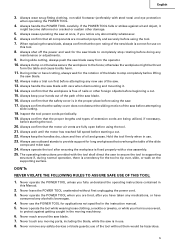
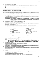
... when they will slide smoothly within the brush holders. The carbon brushes can easily be removed after lifting the lower guard. Exercise utmost caution not to damage the winding by exposing it unsafe to assure that it is in paragraph 1 above. A damaged saw blade can cause personal injury and a worn saw blade. WARNING: To prevent...
... when they will slide smoothly within the brush holders. The carbon brushes can easily be removed after lifting the lower guard. Exercise utmost caution not to damage the winding by exposing it unsafe to assure that it is in paragraph 1 above. A damaged saw blade can cause personal injury and a worn saw blade. WARNING: To prevent...


