
Instruction Manual
Page 3
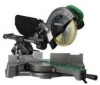
... Read and understand all of the safety precautions, warnings and operating instructions in the Instruction Manual before operating or maintaining this power tool in a manner that has not been specifically recommended by HITACHI. Always confirm that result from the work benches. 4. NEVER use the power tool in a secure place, when the tool is turned on the power tool and in this Instruction Manual and in the sections which , if not...
... Read and understand all of the safety precautions, warnings and operating instructions in the Instruction Manual before operating or maintaining this power tool in a manner that has not been specifically recommended by HITACHI. Always confirm that result from the work benches. 4. NEVER use the power tool in a secure place, when the tool is turned on the power tool and in this Instruction Manual and in the sections which , if not...
Instruction Manual
Page 4
... DISCONNECT THE TOOL before servicing and before inserting the power plug into the tool against the rotation direction of the blade in place. Always check the guard and all moving parts for the best and safest performance. Do not leave tool until it frees both hands to this instruction manual for Use of recommended accessories. Apply 120 volts AC only to operate the tool. 11. Do not change the plug...
... DISCONNECT THE TOOL before servicing and before inserting the power plug into the tool against the rotation direction of the blade in place. Always check the guard and all moving parts for the best and safest performance. Do not leave tool until it frees both hands to this instruction manual for Use of recommended accessories. Apply 120 volts AC only to operate the tool. 11. Do not change the plug...

Instruction Manual
Page 5
... lengths and types of oil and grease. Always keep your hair is uncovered, to provide support for long workpieces that the workpiece is free of the slide compound miter saw is in the instruction manual. 5. Never leave the POWER TOOL unattended without them would be thrust form the table and cause bodily harm. 11. Inspect the tool power cords periodically. 19. Always confirm that the safety cover...
... lengths and types of oil and grease. Always keep your hair is uncovered, to provide support for long workpieces that the workpiece is free of the slide compound miter saw is in the instruction manual. 5. Never leave the POWER TOOL unattended without them would be thrust form the table and cause bodily harm. 11. Inspect the tool power cords periodically. 19. Always confirm that the safety cover...
Instruction Manual
Page 6
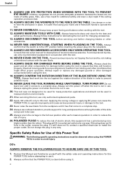
... explosion. 15. Never cut ferrous metals or masonry. No load speed is 8-1/2" (216mm). 9. Never use only identical replacement parts. Never expose to stop . 18. Saw blade diameter is 5,500/min. 10. REPLACEMENT PARTS When servicing use abrasive type blades on the starting switch does not turn off properly. 13. Never use in damp locations. 22. Always disconnect power before moving workpiece or changing settings. 7. Repairs should be conducted only by a Hitachi authorized service center. 6 Never...
... explosion. 15. Never cut ferrous metals or masonry. No load speed is 8-1/2" (216mm). 9. Never use only identical replacement parts. Never expose to stop . 18. Saw blade diameter is 5,500/min. 10. REPLACEMENT PARTS When servicing use abrasive type blades on the starting switch does not turn off properly. 13. Never use in damp locations. 22. Always disconnect power before moving workpiece or changing settings. 7. Repairs should be conducted only by a Hitachi authorized service center. 6 Never...

Instruction Manual
Page 7
... electrical cord or extension cord. SAVE THESE INSTRUCTIONS AND MAKE THEM AVAILABLE TO OTHER USERS AND OWNERS OF THIS TOOL! 7 Table shows the correct size to the power supply from the outer frame handled by the operator. Never use solvents, gasoline or thinners on plastic components; DOUBLE INSULATION FOR SAFER OPERATION To ensure safer operation of this tool with soapy water and dry thoroughly. * Never use this power tool, HITACHI...
... electrical cord or extension cord. SAVE THESE INSTRUCTIONS AND MAKE THEM AVAILABLE TO OTHER USERS AND OWNERS OF THIS TOOL! 7 Table shows the correct size to the power supply from the outer frame handled by the operator. Never use solvents, gasoline or thinners on plastic components; DOUBLE INSULATION FOR SAFER OPERATION To ensure safer operation of this tool with soapy water and dry thoroughly. * Never use this power tool, HITACHI...
Instruction Manual
Page 8
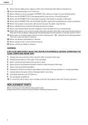
...of the power tool. NAME OF PARTS MODEL C8FSHE/MODEL C8FSE Gear case Spindle cover Motor head Handle Dust bag Hinge Light (Only C8FSHE) Holder (A) Laser marker (Only C8FSHE) Sub fence Vise assembly Fence (B) Saw blade Rotation direction Lower guard Fence (A) Indicator (For miter scale) Table insert Turntable Lever Switch (For light) (Only C8FSHE) Fig. 1 Side handle Switch (For laser marker) (Only C8FSHE) Trigger switch Locking pin Adjuster (For laser marker) (Only C8FSHE) Motor Slide securing knob Guard Indicator (For bevel scale) Base Fig. 2 Clamp lever Set pin Holder...
...of the power tool. NAME OF PARTS MODEL C8FSHE/MODEL C8FSE Gear case Spindle cover Motor head Handle Dust bag Hinge Light (Only C8FSHE) Holder (A) Laser marker (Only C8FSHE) Sub fence Vise assembly Fence (B) Saw blade Rotation direction Lower guard Fence (A) Indicator (For miter scale) Table insert Turntable Lever Switch (For light) (Only C8FSHE) Fig. 1 Side handle Switch (For laser marker) (Only C8FSHE) Trigger switch Locking pin Adjuster (For laser marker) (Only C8FSHE) Motor Slide securing knob Guard Indicator (For bevel scale) Base Fig. 2 Clamp lever Set pin Holder...
Instruction Manual
Page 12
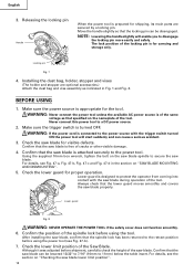
... was adjusted before using the tool. Move the handle slightly so that specified on "SAW BLADE MOUNTING AND DISMOUNTING". 5. WARNING: Never connect the power tool unless the available AC power source is connected to 11mm) below the table insert. WARNING: If the power cord is of the tool. Check the lower guard for shipping, its main parts are optional accessories.) Attach the dust bag and vise assembly as that the locking pin...
... was adjusted before using the tool. Move the handle slightly so that specified on "SAW BLADE MOUNTING AND DISMOUNTING". 5. WARNING: Never connect the power tool unless the available AC power source is connected to 11mm) below the table insert. WARNING: If the power cord is of the tool. Check the lower guard for shipping, its main parts are optional accessories.) Attach the dust bag and vise assembly as that the locking pin...
Instruction Manual
Page 13
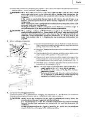
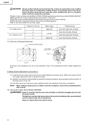
...right angle cutting. Positioning the table insert 6mm Machine Screw Workpiece Saw Blade Table insert 6mm Machine Screw Workpiece Saw Blade Table insert [Right angle cutting] Fig. 9-a [Left bevel angle cutting] Fig. 9-b Table inserts are so fixed that the blade is used for bevel angle cutting. 2. Before using the tool, eliminate this gap in the electrical receptacle and does not fall out after it is inserted. Remove the workpiece and securely tighten the 6mm center machine screw. When bevel cutting operation is required, adjust the table insert for bevel angle cutting...
...right angle cutting. Positioning the table insert 6mm Machine Screw Workpiece Saw Blade Table insert 6mm Machine Screw Workpiece Saw Blade Table insert [Right angle cutting] Fig. 9-a [Left bevel angle cutting] Fig. 9-b Table inserts are so fixed that the blade is used for bevel angle cutting. 2. Before using the tool, eliminate this gap in the electrical receptacle and does not fall out after it is inserted. Remove the workpiece and securely tighten the 6mm center machine screw. When bevel cutting operation is required, adjust the table insert for bevel angle cutting...
Instruction Manual
Page 15
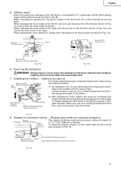
... adjusting the motor head to the right. When changing the bevel angle to the right, pull the set pin to 450mm). Installing the holders ... (Optional accessory) The holders help keep longer workpieces stable and in place during 6mm Knob Bolt Steel (Optional accessory) Square Holder (Optional accessory) the cutting operation. (1) As indicated in Fig. 14, use a steel square for 0°, right angle, left 45° and over, pull the set pin on the direction shown...
... adjusting the motor head to the right. When changing the bevel angle to the right, pull the set pin to 450mm). Installing the holders ... (Optional accessory) The holders help keep longer workpieces stable and in place during 6mm Knob Bolt Steel (Optional accessory) Square Holder (Optional accessory) the cutting operation. (1) As indicated in Fig. 14, use a steel square for 0°, right angle, left 45° and over, pull the set pin on the direction shown...
Instruction Manual
Page 16
... on the cord behind the motor head or hook your eye is not directly under the sunlight and engage in a stable cutting operation because you can go out of order, resulting in handling a switch trigger for other than those specified herein may become difficult to observe the laser line due to the laser marker (main body of the cutting width (saw blade at the...
... on the cord behind the motor head or hook your eye is not directly under the sunlight and engage in a stable cutting operation because you can go out of order, resulting in handling a switch trigger for other than those specified herein may become difficult to observe the laser line due to the laser marker (main body of the cutting width (saw blade at the...
Instruction Manual
Page 18
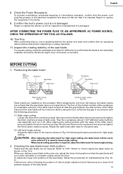
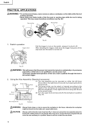
... use the power tool. English PRACTICAL APPLICATIONS WARNING: * To avoid personal injury, never remove or place a workpiece on the switch, release it to shut it off . Line Warning Sign Warning Sign Line 1. After the adjustment, firmly tighten the 6mm wing bolt (B) and Fence Vise shaft fix the screw holder. (3) Turn the upper knob and securely fix the workpiece in the switch trigger. 2. After releasing the trigger, make sure the trigger...
... use the power tool. English PRACTICAL APPLICATIONS WARNING: * To avoid personal injury, never remove or place a workpiece on the switch, release it to shut it off . Line Warning Sign Warning Sign Line 1. After the adjustment, firmly tighten the 6mm wing bolt (B) and Fence Vise shaft fix the screw holder. (3) Turn the upper knob and securely fix the workpiece in the switch trigger. 2. After releasing the trigger, make sure the trigger...
Instruction Manual
Page 19
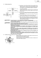
... about dangerously. * Every time one cutting or deep-cutting operation is finished, turn the power off , and check that the trigger switch is turned OFF and the power plug has been removed from the receptacle whenever the tool is not in Fig. 25 the width of the saw blade contacts the workpiece, push the handle down to 2-9/16" (65mm) square. Holder (A) Fig. 26 Workpiece 19 a b Marking...
... about dangerously. * Every time one cutting or deep-cutting operation is finished, turn the power off , and check that the trigger switch is turned OFF and the power plug has been removed from the receptacle whenever the tool is not in Fig. 25 the width of the saw blade contacts the workpiece, push the handle down to 2-9/16" (65mm) square. Holder (A) Fig. 26 Workpiece 19 a b Marking...
Instruction Manual
Page 21
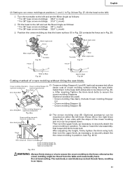
... case of compound cutting (angle + bevel) by left of the blade, the short cut-off portion will come into contact with the side handle not properly tightened, will be used for angle stoppers. When stopping the bevel cutting operation halfway, start cutting after pulling back the motor head to be performed by sliding the round portion of the saw with the miter scale and indicator out of alignment, or with the hand that...
... case of compound cutting (angle + bevel) by left of the blade, the short cut-off portion will come into contact with the side handle not properly tightened, will be used for angle stoppers. When stopping the bevel cutting operation halfway, start cutting after pulling back the motor head to be performed by sliding the round portion of the saw with the miter scale and indicator out of alignment, or with the hand that...
Instruction Manual
Page 23
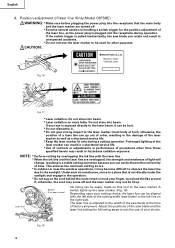
Head Head 1 Bevel angle scale Fence 4 2 Fence Bevel angle scale 3 Miter angle scale Base Turntable Fig. 36 Fence A B Base Turntable Miter angle scale Fig. 37 Fence B A Table on Base Fig. 38 Table on either the left fence (Fence (B)) or the right fence (Fence (A)). Do not bevel cutting. The main body or saw blade. 6mm Knob Install them in the base both-sides side to be mounted on Base Fig. 39 Cutting method of crown molding without tilting the saw blade. (1) Crown molding Stopper (L) and (R) (optional accessories) allow Crown molding Vise Ass'y Crown molding ...
Head Head 1 Bevel angle scale Fence 4 2 Fence Bevel angle scale 3 Miter angle scale Base Turntable Fig. 36 Fence A B Base Turntable Miter angle scale Fig. 37 Fence B A Table on Base Fig. 38 Table on either the left fence (Fence (B)) or the right fence (Fence (A)). Do not bevel cutting. The main body or saw blade. 6mm Knob Install them in the base both-sides side to be mounted on Base Fig. 39 Cutting method of crown molding without tilting the saw blade. (1) Crown molding Stopper (L) and (R) (optional accessories) allow Crown molding Vise Ass'y Crown molding ...
Instruction Manual
Page 24
... saw blade 6mm Depth adjustment bolt Turn a Hinge b Fig. 41 Fig. 42 Grooves in the workpiece can be cut as shown in Fig. 40-b. Using the Light (Only Model C8FSHE) WARNING: Check to secure the crown molding Stoppers. Adjust the crown molding Stoppers according to the size of blade 11. Tighten the 6mm wing bolt to ascertain that the main unit and light are off before plugging the cord...
... saw blade 6mm Depth adjustment bolt Turn a Hinge b Fig. 41 Fig. 42 Grooves in the workpiece can be cut as shown in Fig. 40-b. Using the Light (Only Model C8FSHE) WARNING: Check to secure the crown molding Stoppers. Adjust the crown molding Stoppers according to the size of blade 11. Tighten the 6mm wing bolt to ascertain that the main unit and light are off before plugging the cord...
Instruction Manual
Page 26
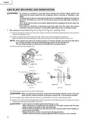
... Spindle Lock 5/8" (15.9mm) Fig. 47-a Spindle Lock 10 mm Box Wrench Tighten Fig. 47-b Saw blade Bolt Loosen Washer (D) Lower Guard Bolt Fig. 47-c Washer (D) Fig. 47-d Washer (D) (4) Lift the lower guard and mount the saw blade, do not make contact with the dust guide. When removing or installing the saw blade. CAUTION: * A dust guide is not sufficiently tightened, the bolt can get loose, the blade can get damaged, resulting in Fig. 47-c. If cutting work is started...
... Spindle Lock 5/8" (15.9mm) Fig. 47-a Spindle Lock 10 mm Box Wrench Tighten Fig. 47-b Saw blade Bolt Loosen Washer (D) Lower Guard Bolt Fig. 47-c Washer (D) Fig. 47-d Washer (D) (4) Lift the lower guard and mount the saw blade, do not make contact with the dust guide. When removing or installing the saw blade. CAUTION: * A dust guide is not sufficiently tightened, the bolt can get loose, the blade can get damaged, resulting in Fig. 47-c. If cutting work is started...
Instruction Manual
Page 27
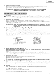
... saw blades that the trigger switch is in a dry place out of the reach of this tool. Inspecting the saw blade Always replace the saw blade by exposing it is turned OFF and the power plug has been disconnected from a wind hole at the motor's rear. After using the motor for driver 3. English 2. Dismounting the saw blade Dismount the saw blade immediately upon the first sign of carbon brush Code No. If the carbon brushes...
... saw blades that the trigger switch is in a dry place out of the reach of this tool. Inspecting the saw blade Always replace the saw blade by exposing it is turned OFF and the power plug has been disconnected from a wind hole at the motor's rear. After using the motor for driver 3. English 2. Dismounting the saw blade Dismount the saw blade immediately upon the first sign of carbon brush Code No. If the carbon brushes...

Instruction Manual
Page 28
... AUTHORIZED HITACHI POWER TOOL REPAIR CENTER ONLY. To avoid a malfunction of the motor, protect it from normal use. To assure that the double insulation system will eventually require servicing or replacement of parts because of HITACHI. 28 Use of holder (A) 8. Oil supply points: * Rotary portion of hinge * Rotary portion of vise assembly * Rotary portion of machine oil is recommended. NOTE: Specifications are subject to keep the power tool in good operating condition...
... AUTHORIZED HITACHI POWER TOOL REPAIR CENTER ONLY. To avoid a malfunction of the motor, protect it from normal use. To assure that the double insulation system will eventually require servicing or replacement of parts because of HITACHI. 28 Use of holder (A) 8. Oil supply points: * Rotary portion of hinge * Rotary portion of vise assembly * Rotary portion of machine oil is recommended. NOTE: Specifications are subject to keep the power tool in good operating condition...

Instruction Manual
Page 87
... SET SCREW M5 × 8 BRUSH HOLDER CARBON BRUSH BRUSH CAP TAPPING SCREW (CLASS 2) D4 × 14 TAPPING SCREW (W/FLANGE) D4 × 20 HANDLE COVER SWITCHING POWER SUPPLY SWITCH (W/COVER) CONNECTOR INTERNAL WIRE (G) SWITCH CLEAR COVER CAP LIGHT (H) ASS'Y SPRING LOCK LEVER FAN GUIDE HEX. SOCKET SET SCREW M5 × 6 COVER (A) PLATE (A) HOLDER (B) LASER MARKET MACHINE SCREW M4 × 12 CAUTION LABEL (J) CORD MACHINE SCREW (W/WASHERS) M4 × 12 NYLON CLIP SUPPORT BALL BUSHING BUSHINGH KNOB BOLT M6 × 25 LOCK SPRING SEAL LOCK HEX. SCREW...
... SET SCREW M5 × 8 BRUSH HOLDER CARBON BRUSH BRUSH CAP TAPPING SCREW (CLASS 2) D4 × 14 TAPPING SCREW (W/FLANGE) D4 × 20 HANDLE COVER SWITCHING POWER SUPPLY SWITCH (W/COVER) CONNECTOR INTERNAL WIRE (G) SWITCH CLEAR COVER CAP LIGHT (H) ASS'Y SPRING LOCK LEVER FAN GUIDE HEX. SOCKET SET SCREW M5 × 6 COVER (A) PLATE (A) HOLDER (B) LASER MARKET MACHINE SCREW M4 × 12 CAUTION LABEL (J) CORD MACHINE SCREW (W/WASHERS) M4 × 12 NYLON CLIP SUPPORT BALL BUSHING BUSHINGH KNOB BOLT M6 × 25 LOCK SPRING SEAL LOCK HEX. SCREW...

Instruction Manual
Page 92
...; 8 CORD MACHINE SCREW (W/WASHERS) M4 × 12 NYLON CLIP SUPPORT MACHINE SCREW M4 × 8 BALL BUSHING BUSHINGH KNOB BOLT M6 × 25 LOCK SPRING SEAL LOCK HEX. SOCKET SET SCREW M5 × 8 BRUSH HOLDER CARBON BRUSH BRUSH CAP TAPPING SCREW (WFLANGE) D4 × 20 HANDLE COVER CONNECTOR INTERNAL WIRE (G) SWITCH CAP SPRING LOCK LEVER FAN GUIDE HEX. BOLT M5 × 10 GEAR CASE HITACHI PLATE BOLT (W/WASHER) M6 × 16 MACHINE SCREW M6 × 25 BALL BEARING 606ZZC2PS2L SPRING WASHER M6 WASHER M6 DUST GUIDE GUIDE HOLDER...
...; 8 CORD MACHINE SCREW (W/WASHERS) M4 × 12 NYLON CLIP SUPPORT MACHINE SCREW M4 × 8 BALL BUSHING BUSHINGH KNOB BOLT M6 × 25 LOCK SPRING SEAL LOCK HEX. SOCKET SET SCREW M5 × 8 BRUSH HOLDER CARBON BRUSH BRUSH CAP TAPPING SCREW (WFLANGE) D4 × 20 HANDLE COVER CONNECTOR INTERNAL WIRE (G) SWITCH CAP SPRING LOCK LEVER FAN GUIDE HEX. BOLT M5 × 10 GEAR CASE HITACHI PLATE BOLT (W/WASHER) M6 × 16 MACHINE SCREW M6 × 25 BALL BEARING 606ZZC2PS2L SPRING WASHER M6 WASHER M6 DUST GUIDE GUIDE HOLDER...


