
Owners Guide
Page 9
... inputs, ANT A and ANT B. ANT B can only be displayed as a main picture. (ANT B cannot be set as a center channel by selecting "TV as Center" on the Audio Advanced Settings Menu (see page 47). ቧ S-VIDEO Inputs 3 and 4 Inputs 3 and 4 provide S-VIDEO (Super Video)... sub-picture. REAR PANEL JACKS ቢ ANT A TO CONVERTER ANT B AUDIO TO HI-FI CENTER IN IR BLASTER L R ባ ቪ ቨ INPUT 1 INPUT 2 DVI-HDTV PR PB Y R (MONO)/L AUDIO PR PB Y/VIDEO R (MONO)/L AUDIO INPUT 3 R (MONO)/L VIDEO INPUT 4 R (MONO)/L VIDEO MONITOR OUT R L AUDIO VIDEO S-VIDEO S-VIDEO...
... inputs, ANT A and ANT B. ANT B can only be displayed as a main picture. (ANT B cannot be set as a center channel by selecting "TV as Center" on the Audio Advanced Settings Menu (see page 47). ቧ S-VIDEO Inputs 3 and 4 Inputs 3 and 4 provide S-VIDEO (Super Video)... sub-picture. REAR PANEL JACKS ቢ ANT A TO CONVERTER ANT B AUDIO TO HI-FI CENTER IN IR BLASTER L R ባ ቪ ቨ INPUT 1 INPUT 2 DVI-HDTV PR PB Y R (MONO)/L AUDIO PR PB Y/VIDEO R (MONO)/L AUDIO INPUT 3 R (MONO)/L VIDEO INPUT 4 R (MONO)/L VIDEO MONITOR OUT R L AUDIO VIDEO S-VIDEO S-VIDEO...

Owners Guide
Page 10
... picture can be abnormal, when using the Y-PBPR inputs. (See page 41) 5. In this case, connect the component CB output to the TV's PB input and the component CR output to obtain optimum picture quality when using the Y-PBPR jacks. 6. Do not connect composite VIDEO and S-VIDEO...4. S-VIDEO has priority over VIDEO input. 2. In this case, connect the components B-Y output to the TV's PB input and the components R-Y output to Input 3, 4 or 5 at the same time. The DVI-HDTV input is also for future use standard video signal for INPUT:2. Your component outputs may be labeled Y, B-Y,...
... picture can be abnormal, when using the Y-PBPR inputs. (See page 41) 5. In this case, connect the component CB output to the TV's PB input and the component CR output to obtain optimum picture quality when using the Y-PBPR jacks. 6. Do not connect composite VIDEO and S-VIDEO...4. S-VIDEO has priority over VIDEO input. 2. In this case, connect the components B-Y output to the TV's PB input and the components R-Y output to Input 3, 4 or 5 at the same time. The DVI-HDTV input is also for future use standard video signal for INPUT:2. Your component outputs may be labeled Y, B-Y,...

Owners Guide
Page 11
...-Top Box Y PB PR L R OUTPUT ANT A TO CONVERTER ANT B AUDIO TO HI-FI CENTER IN IR BLASTER L R INPUT 1 DVI-HDTV PR PB Y R (MONO)/L AUDIO INPUT 2 PR PB Y/VIDEO R (MONO)/L AUDIO INPUT 3 INPUT 4 R (MONO)/L VIDEO R (MONO)/L VIDEO MONITOR OUT ...R L AUDIO VIDEO S-VIDEO S-VIDEO S-VIDEO VCR #1 ANT OUTPUT IN S-VIDEO V L R INPUT OUTPUT Cable TV Box LR INPUT Infrared S-VIDEO V L R Receiver INPUT S-VIDEO V L R OUTPUT Stereo System Amplifier CONNECT TO IR BLASTER VCR #2 (Provided) Laserdisc player, VCR, camcorder, etc...
...-Top Box Y PB PR L R OUTPUT ANT A TO CONVERTER ANT B AUDIO TO HI-FI CENTER IN IR BLASTER L R INPUT 1 DVI-HDTV PR PB Y R (MONO)/L AUDIO INPUT 2 PR PB Y/VIDEO R (MONO)/L AUDIO INPUT 3 INPUT 4 R (MONO)/L VIDEO R (MONO)/L VIDEO MONITOR OUT ...R L AUDIO VIDEO S-VIDEO S-VIDEO S-VIDEO VCR #1 ANT OUTPUT IN S-VIDEO V L R INPUT OUTPUT Cable TV Box LR INPUT Infrared S-VIDEO V L R Receiver INPUT S-VIDEO V L R OUTPUT Stereo System Amplifier CONNECT TO IR BLASTER VCR #2 (Provided) Laserdisc player, VCR, camcorder, etc...

Owners Guide
Page 13
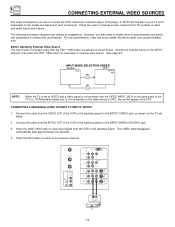
CONNECTION EXTERNAL AUDIO SOURCES To control the audio level of the TV set. 13 REAR PANEL OF TELEVISION ANT A TO CONVERTER ANT B AUDIO TO HI-FI CENTER IN IR BLASTER L R INPUT 1 INPUT 2 DVI-HDTV PR PB Y R (MONO)/L AUDIO PR PB Y/VIDEO R (MONO)/L AUDIO INPUT 3 R (MONO)/L VIDEO INPUT 4 R (MONO)/L VIDEO MONITOR OUT R L AUDIO VIDEO...
CONNECTION EXTERNAL AUDIO SOURCES To control the audio level of the TV set. 13 REAR PANEL OF TELEVISION ANT A TO CONVERTER ANT B AUDIO TO HI-FI CENTER IN IR BLASTER L R INPUT 1 INPUT 2 DVI-HDTV PR PB Y R (MONO)/L AUDIO PR PB Y/VIDEO R (MONO)/L AUDIO INPUT 3 R (MONO)/L VIDEO INPUT 4 R (MONO)/L VIDEO MONITOR OUT R L AUDIO VIDEO...
Owners Guide
Page 14
... component for the location of video and audio inputs and outputs. Connect the cable from the VIDEO INPUT JACK on the back panel of the TV (i.e., VCR/laserdisc player, etc. The VIDEO label disappears automatically after approximately four seconds. 4. Check the owner's manual of each component. For best ...and a video signal is dependent on the TV set is not received from the AUDIO OUT of the VCR or the laserdisc player to the INPUT (MONO)/L(AUDIO) jack. 3. ANT A TO CONVERTER ANT B AUDIO TO HI-FI CENTER IN IR BLASTER L R INPUT 1 INPUT 2 DVI-HDTV PR PB Y R (MONO)/L AUDIO PR ...
... component for the location of video and audio inputs and outputs. Connect the cable from the VIDEO INPUT JACK on the back panel of the TV (i.e., VCR/laserdisc player, etc. The VIDEO label disappears automatically after approximately four seconds. 4. Check the owner's manual of each component. For best ...and a video signal is dependent on the TV set is not received from the AUDIO OUT of the VCR or the laserdisc player to the INPUT (MONO)/L(AUDIO) jack. 3. ANT A TO CONVERTER ANT B AUDIO TO HI-FI CENTER IN IR BLASTER L R INPUT 1 INPUT 2 DVI-HDTV PR PB Y R (MONO)/L AUDIO PR ...

Owners Guide
Page 15
Connect the cable from the VIDEO OUT of the VCR or the laserdisc player to your VCR operating guide for more information on the TV set below. 2. Press the ANT button to return to rear panel jacks. ANT A TO CONVERTER ANT B AUDIO TO HI-FI CENTER IN IR BLASTER L R ...INPUT 1 INPUT 2 INPUT 3 DVI-HDTV PR PB Y R (MONO)/L AUDIO PR PB Y/VIDEO R (MONO)/L AUDIO R (MONO)/L VIDEO INPUT 4 R (MONO)/L VIDEO MONITOR OUT R L AUDIO VIDEO S-VIDEO S-VIDEO S-VIDEO OUTPUT RL V ...
Connect the cable from the VIDEO OUT of the VCR or the laserdisc player to your VCR operating guide for more information on the TV set below. 2. Press the ANT button to return to rear panel jacks. ANT A TO CONVERTER ANT B AUDIO TO HI-FI CENTER IN IR BLASTER L R ...INPUT 1 INPUT 2 INPUT 3 DVI-HDTV PR PB Y R (MONO)/L AUDIO PR PB Y/VIDEO R (MONO)/L AUDIO R (MONO)/L VIDEO INPUT 4 R (MONO)/L VIDEO MONITOR OUT R L AUDIO VIDEO S-VIDEO S-VIDEO S-VIDEO OUTPUT RL V ...

Owners Guide
Page 16
ANT A TO CONVERTER ANT B AUDIO TO HI-FI CENTER IN IR BLASTER L R INPUT 1 INPUT 2 INPUT 3 DVI-HDTV PR PB Y R (MONO)/L AUDIO PR PB Y/VIDEO R (MONO)/L AUDIO R (MONO)/L VIDEO INPUT 4 R (MONO)/L VIDEO MONITOR OUT R L AUDIO VIDEO S-VIDEO S-VIDEO S-VIDEO OUTPUT RL V S-VIDEO VCR ... VIDEO label disappears automatically after approximately four seconds. 5. Press the VID3~VID5 button to the INPUT (S-VIDEO) jack, as shown on line input-output connections. 16 A single VCR can be abnormal if the connection is played back will be used for more information on the...
ANT A TO CONVERTER ANT B AUDIO TO HI-FI CENTER IN IR BLASTER L R INPUT 1 INPUT 2 INPUT 3 DVI-HDTV PR PB Y R (MONO)/L AUDIO PR PB Y/VIDEO R (MONO)/L AUDIO R (MONO)/L VIDEO INPUT 4 R (MONO)/L VIDEO MONITOR OUT R L AUDIO VIDEO S-VIDEO S-VIDEO S-VIDEO OUTPUT RL V S-VIDEO VCR ... VIDEO label disappears automatically after approximately four seconds. 5. Press the VID3~VID5 button to the INPUT (S-VIDEO) jack, as shown on line input-output connections. 16 A single VCR can be abnormal if the connection is played back will be used for more information on the...

Owners Guide
Page 17
... 1. Press the VID1~VID2 button, to the INPUT (Y) jack, as shown on REAR PANEL CONNECTIONS. 17 See page 12 for tips on the TV set top box. Press the ANT button to return to rear panel jacks. Completely insert the connection cord plugs when connecting to the previous channel...back will be abnormal if the connection is loose. 2. Connect the cable from the CR/PR OUT or R-Y OUT of the Laserdisc/DVD player or HDTV set top box to the INPUT (AUDIO/R) jack. 5. The VIDEO label disappears automatically after approximately four seconds. 7. Connect the cable from the AUDIO ...
... 1. Press the VID1~VID2 button, to the INPUT (Y) jack, as shown on REAR PANEL CONNECTIONS. 17 See page 12 for tips on the TV set top box. Press the ANT button to return to rear panel jacks. Completely insert the connection cord plugs when connecting to the previous channel...back will be abnormal if the connection is loose. 2. Connect the cable from the CR/PR OUT or R-Y OUT of the Laserdisc/DVD player or HDTV set top box to the INPUT (AUDIO/R) jack. 5. The VIDEO label disappears automatically after approximately four seconds. 7. Connect the cable from the AUDIO ...
Owners Guide
Page 18
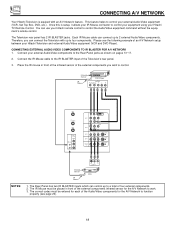
...Sensor IR Mouse DVD Player OUTPUT PR/CR PB/CB Y L R ANT A TO CONVERTER ANT B AUDIO TO HI-FI CENTER IN IR BLASTER L R INPUT 1 DVI-HDTV PR PB Y R (MONO)/L INPUT 2 PR PB Y/VIDEO R (MONO)/L AUDIO INPUT 3 R (MONO)/L VIDEO INPUT 4 R (MONO)/L VIDEO MONITOR OUT R L AUDIO... VCR 1. CONNECTING EXTERNAL AUDIO/VIDEO COMPONENTS TO IR BLASTER FOR A/V NETWORK 1. CONNECTING A/V NETWORK Your Hitachi Television is setup, it allows your IR Mouse connector to control your equipment using your Hitachi TV Remote Control. The Rear Panel has two IR BLASTER inputs which can use your...
...Sensor IR Mouse DVD Player OUTPUT PR/CR PB/CB Y L R ANT A TO CONVERTER ANT B AUDIO TO HI-FI CENTER IN IR BLASTER L R INPUT 1 DVI-HDTV PR PB Y R (MONO)/L INPUT 2 PR PB Y/VIDEO R (MONO)/L AUDIO INPUT 3 R (MONO)/L VIDEO INPUT 4 R (MONO)/L VIDEO MONITOR OUT R L AUDIO... VCR 1. CONNECTING EXTERNAL AUDIO/VIDEO COMPONENTS TO IR BLASTER FOR A/V NETWORK 1. CONNECTING A/V NETWORK Your Hitachi Television is setup, it allows your IR Mouse connector to control your equipment using your Hitachi TV Remote Control. The Rear Panel has two IR BLASTER inputs which can use your...

Owners Guide
Page 25
HOW TO USE THE REMOTE TO CONTROL YOUR TV ተ ASPECT button Press this aspect mode to display conventional (4:3) images. Phosphors in the lighted area of the picture will age ...mode to display 16:9 sources like HDTV and DVD's preserving the original 16:9 aspect ratio. 16:9 Zoom Use this aspect mode to zoom in 16:9 aspect. (1) NTSC Input 4:3 INPUT 4:3 STANDARD 4:3 EXPANDED 4:3 ZOOM1 (2) 480i/480p INPUT 16:9 INPUT 16:9 ZOOM 4:3 STANDARD 16:9 STANDARD 4:3 EXPANDED 4:3 ZOOM2 4:3 ZOOM1 (3) 720p/1080i INPUT 16:9 INPUT 16:9 ZOOM 16:9 STANDARD 16:9 STANDARD 4:3 ZOOM2 16:9 ZOOM 25...
HOW TO USE THE REMOTE TO CONTROL YOUR TV ተ ASPECT button Press this aspect mode to display conventional (4:3) images. Phosphors in the lighted area of the picture will age ...mode to display 16:9 sources like HDTV and DVD's preserving the original 16:9 aspect ratio. 16:9 Zoom Use this aspect mode to zoom in 16:9 aspect. (1) NTSC Input 4:3 INPUT 4:3 STANDARD 4:3 EXPANDED 4:3 ZOOM1 (2) 480i/480p INPUT 16:9 INPUT 16:9 ZOOM 4:3 STANDARD 16:9 STANDARD 4:3 EXPANDED 4:3 ZOOM2 4:3 ZOOM1 (3) 720p/1080i INPUT 16:9 INPUT 16:9 ZOOM 16:9 STANDARD 16:9 STANDARD 4:3 ZOOM2 16:9 ZOOM 25...
Owners Guide
Page 28
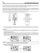
...The Picture-in-Picture feature is for improved viewing enjoyment. ANT A TO CONVERTER ANT B AUDIO TO HI-FI CENTER IN IR BLASTER L R INPUT 1 INPUT 2 DVI-HDTV PR PB Y R (MONO)/L AUDIO PR PB Y/VIDEO R (MONO)/L AUDIO INPUT 3 R (MONO)/L VIDEO INPUT 4 R (MONO)/L VIDEO MONITOR OUT R L VIDEO...In POP mode, thumb stick CURSOR ̆ , ̄ will move the sub picture up/down. PICTURE-IN-PICTURE (PIP) Your HITACHI Projection TV incorporates Dual Tuner technology designed for the main picture. This Dual Tuner feature allows you want to cycle through the four different modes. When...
...The Picture-in-Picture feature is for improved viewing enjoyment. ANT A TO CONVERTER ANT B AUDIO TO HI-FI CENTER IN IR BLASTER L R INPUT 1 INPUT 2 DVI-HDTV PR PB Y R (MONO)/L AUDIO PR PB Y/VIDEO R (MONO)/L AUDIO INPUT 3 R (MONO)/L VIDEO INPUT 4 R (MONO)/L VIDEO MONITOR OUT R L VIDEO...In POP mode, thumb stick CURSOR ̆ , ̄ will move the sub picture up/down. PICTURE-IN-PICTURE (PIP) Your HITACHI Projection TV incorporates Dual Tuner technology designed for the main picture. This Dual Tuner feature allows you want to cycle through the four different modes. When...

Owners Guide
Page 44
... STICK to change tint and color coordinates for High Vision Signal Y-PBPR from HDTV Set-Top Box. Use for DTV programs. HDTV - NOTES: 1. Press down on THUMB STICK to access an ADVANCED SETTINGS ...feature. Scan Velocity Modulation The Scan Velocity Modulation function automatically enhances the edges between light and dark areas. VIDEO Color System This function allows you to automatically change COLOR TEMPERATURE setting. If Color System is selected. Advanced Settings Your HITACHI Projection TV...
... STICK to change tint and color coordinates for High Vision Signal Y-PBPR from HDTV Set-Top Box. Use for DTV programs. HDTV - NOTES: 1. Press down on THUMB STICK to access an ADVANCED SETTINGS ...feature. Scan Velocity Modulation The Scan Velocity Modulation function automatically enhances the edges between light and dark areas. VIDEO Color System This function allows you to automatically change COLOR TEMPERATURE setting. If Color System is selected. Advanced Settings Your HITACHI Projection TV...

Owners Guide
Page 66
..., 60Hz • Stand-by BBE Sound, Inc. Manufactured under USP4638258 and 4482866. in .) 25 1/16 • Weight (lbs.) 238 57SWX20B 57TWX20B 54 3/16 54 25 8/16 265 65SWX20B 65TWX20B 59 7/8 61 28 319 NOTE: Due to change without notice. 66 HDTV DVI 25pin Outputs: • Video 1.0Vp-p. 75 Ohm • Audio (Fixed 470mVrms, 1k Ohm...
..., 60Hz • Stand-by BBE Sound, Inc. Manufactured under USP4638258 and 4482866. in .) 25 1/16 • Weight (lbs.) 238 57SWX20B 57TWX20B 54 3/16 54 25 8/16 265 65SWX20B 65TWX20B 59 7/8 61 28 319 NOTE: Due to change without notice. 66 HDTV DVI 25pin Outputs: • Video 1.0Vp-p. 75 Ohm • Audio (Fixed 470mVrms, 1k Ohm...


