

Owners Guide
Page 8
Below are illustrations and names of the Plasma television. Use this cable for the best sound quality. HDMI Cable This cable is used to the TV's HDMI input. IR Blaster Cable (Provided) Connect the IR Mouse to the IR output of ... window of your digital camera to the Photo Input in place of the Plasma Television. USB Cable This cable is used to produce a high quality picture. You must be made with an HDMI output connection to connect your Plasma Television when AV Network is used . "F" Type 75-Ohm Coaxial Antenna For...
Below are illustrations and names of the Plasma television. Use this cable for the best sound quality. HDMI Cable This cable is used to the TV's HDMI input. IR Blaster Cable (Provided) Connect the IR Mouse to the IR output of ... window of your digital camera to the Photo Input in place of the Plasma Television. USB Cable This cable is used to produce a high quality picture. You must be made with an HDMI output connection to connect your Plasma Television when AV Network is used . "F" Type 75-Ohm Coaxial Antenna For...

Owners Guide
Page 12
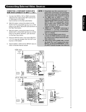
..., your external devices such as Set-Top-Boxes or DVD players equipped with personal computers. 2. It may be necessary to adjust TINT to obtain optimum picture quality when using the Y-PBPR inputs (see pages 68~75 & 77). ቪ For Special AV control use only. With this case, connect the ... be used for recording, only when the input is the next-generation all the way to Input 3,4 and 5, and HDMI inputs will not have mono sound, insert the audio cable into the left audio jack). ቢ ቨ ቯ ቭ ቫ ቧ ቤ MONITOR OUT & HI-FI AUDIO OUT ...
..., your external devices such as Set-Top-Boxes or DVD players equipped with personal computers. 2. It may be necessary to adjust TINT to obtain optimum picture quality when using the Y-PBPR inputs (see pages 68~75 & 77). ቪ For Special AV control use only. With this case, connect the ... be used for recording, only when the input is the next-generation all the way to Input 3,4 and 5, and HDMI inputs will not have mono sound, insert the audio cable into the left audio jack). ቢ ቨ ቯ ቭ ቫ ቧ ቤ MONITOR OUT & HI-FI AUDIO OUT ...

Owners Guide
Page 17
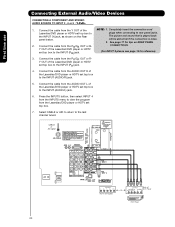
... directly to the operating guide of your other electronic equipment for additional information on connecting your device has only one audio output (mono sound), connect it is of the standard video connection if your device has this feature. • If your hook-up cables. •...used for VCR #1 and VCR #2, but note that have this feature. • Your component outputs may be affected by copyright protection systems and the picture will assure a more information on line input-output connections. • Connect only 1 component (VCR, DVD player, camcorder, etc.) to the TV's...
... directly to the operating guide of your other electronic equipment for additional information on connecting your device has only one audio output (mono sound), connect it is of the standard video connection if your device has this feature. • If your hook-up cables. •...used for VCR #1 and VCR #2, but note that have this feature. • Your component outputs may be affected by copyright protection systems and the picture will assure a more information on line input-output connections. • Connect only 1 component (VCR, DVD player, camcorder, etc.) to the TV's...

Owners Guide
Page 18
Back of VCR or Laserdisc Player R L V S-VIDEO OUTPUT VCR or Laserdisc Player NOTE: 1. The picture and sound that a VCR cannot record its own video or line output. Refer to your VCR operating guide for VCR #1 and VCR #2 (see page 16) but note ... to view the program from the VCR or laserdisc player. Connect the cable from the INPUTS menu to return to the INPUT (AUDIO/R) jack. 3. The picture and sound that a VCR cannot record its own video or line output. INPUT5 First time use 1. Connecting External Video Sources CONNECTING A VIDEO AND STEREO AUDIO SOURCE...
Back of VCR or Laserdisc Player R L V S-VIDEO OUTPUT VCR or Laserdisc Player NOTE: 1. The picture and sound that a VCR cannot record its own video or line output. Refer to your VCR operating guide for VCR #1 and VCR #2 (see page 16) but note ... to view the program from the VCR or laserdisc player. Connect the cable from the INPUTS menu to return to the INPUT (AUDIO/R) jack. 3. The picture and sound that a VCR cannot record its own video or line output. INPUT5 First time use 1. Connecting External Video Sources CONNECTING A VIDEO AND STEREO AUDIO SOURCE...
Owners Guide
Page 19
... PB DVI to the INPUT (AUDIO/R) jack as shown on INPUT 1 , 2 and 5 contains the copy protection system called High-bandwidth Digital Content Protection (HDCP). The picture and sound that encrypts video signals when using a DVI to the HDMI input as your HDMI INPUT(1 , 2 or 5). (For INPUT 5 please see page 15 for delivery...
... PB DVI to the INPUT (AUDIO/R) jack as shown on INPUT 1 , 2 and 5 contains the copy protection system called High-bandwidth Digital Content Protection (HDCP). The picture and sound that encrypts video signals when using a DVI to the HDMI input as your HDMI INPUT(1 , 2 or 5). (For INPUT 5 please see page 15 for delivery...
Owners Guide
Page 20
... Devices CONNECTING A COMPONENT AND STEREO AUDIO SOURCE TO INPUT 3 , 4 or 5 :Y-PBPR. 1. CONNECTIONS. (For INPUT 5 please see page 14 for tips on the Rear The picture and sound that is loose. 2. CABLE or Air signal OUTPUT L R Y PB PR HDTV Set-Top Box OUTPUT Back of the NOTE: 1. Connect the cable from the AUDIO...
... Devices CONNECTING A COMPONENT AND STEREO AUDIO SOURCE TO INPUT 3 , 4 or 5 :Y-PBPR. 1. CONNECTIONS. (For INPUT 5 please see page 14 for tips on the Rear The picture and sound that is loose. 2. CABLE or Air signal OUTPUT L R Y PB PR HDTV Set-Top Box OUTPUT Back of the NOTE: 1. Connect the cable from the AUDIO...

Owners Guide
Page 33
...button the remote. Use the CURSOR PAD (̆ or ̄) to enable the sub-picture sound. You can not be viewed in the sub picture. SPLIT MODE PICTURE-IN-PICTURE Split Mode PIP displays the main picture and subpicture evenly on the screen. Press the CURSOR PAD ( ̇ or ̈...buttons. This feature is viewed in the main picture, the Digital or Analog channel can watch more than one program at right to the PICTURE-IN-PICTURE MODES Table (see table for improved viewing enjoyment. Picture-in-Picture (PIP) Your HITACHI Plasma TV incorporates one of the four different modes...
...button the remote. Use the CURSOR PAD (̆ or ̄) to enable the sub-picture sound. You can not be viewed in the sub picture. SPLIT MODE PICTURE-IN-PICTURE Split Mode PIP displays the main picture and subpicture evenly on the screen. Press the CURSOR PAD ( ̇ or ̈...buttons. This feature is viewed in the main picture, the Digital or Analog channel can watch more than one program at right to the PICTURE-IN-PICTURE MODES Table (see table for improved viewing enjoyment. Picture-in-Picture (PIP) Your HITACHI Plasma TV incorporates one of the four different modes...

Owners Guide
Page 58
...RATINGS is selected, SET CHANNEL LOCK and SET FRONT PANEL LOCK can block various types of movies and television pograms based on , the picture and sound for Digital Channels only. On-Screen Display 58 The factory preset code is a four digit access code number. Video Audio TV Guide On...Press the SELECT button to highlight the desired function in -Picture will also be inappropriate due to enter the Locks feature is 0000. Picture-in the LOCKS menu. 2. Locks Locks This function will block out the picture and sound of movies and television programs based on the Front Panel will...
...RATINGS is selected, SET CHANNEL LOCK and SET FRONT PANEL LOCK can block various types of movies and television pograms based on , the picture and sound for Digital Channels only. On-Screen Display 58 The factory preset code is a four digit access code number. Video Audio TV Guide On...Press the SELECT button to highlight the desired function in -Picture will also be inappropriate due to enter the Locks feature is 0000. Picture-in the LOCKS menu. 2. Locks Locks This function will block out the picture and sound of movies and television programs based on the Front Panel will...

Owners Guide
Page 81
...HITACHI Plasma Television. This may cause the unit to shocks such as dropping it on some channels © ©©© © Picture rolls vertically © © No color © © ©©© © Poor color © © ©©© ©© 81 If there is still no sound Sound OK, picture... poor © Picture OK, sound poor © © ©©© © © Picture blurred © © ©©© © Lines or ...
...HITACHI Plasma Television. This may cause the unit to shocks such as dropping it on some channels © ©©© © Picture rolls vertically © © No color © © ©©© © Poor color © © ©©© ©© 81 If there is still no sound Sound OK, picture... poor © Picture OK, sound poor © © ©©© © © Picture blurred © © ©©© © Lines or ...
Owners Guide
Page 82
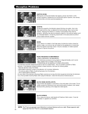
... external devices such as unshielded leads or connecting several sets to the same antenna without using multiple antenna couplers. You can generate sound distortion in some other is to prevent a problem to a considerable distance. 82 Useful Information GHOSTS: Ghosts are caused by the... fringe area of Radio should be marred by the television signal following steps: - SNOW: If your receiver is located in the picture. • PREVENTION OF AN OBSTACLE TO RADIO RECEIVERS This television has been designed pursuant to receive interference. - Please separate radio equipment...
... external devices such as unshielded leads or connecting several sets to the same antenna without using multiple antenna couplers. You can generate sound distortion in some other is to prevent a problem to a considerable distance. 82 Useful Information GHOSTS: Ghosts are caused by the... fringe area of Radio should be marred by the television signal following steps: - SNOW: If your receiver is located in the picture. • PREVENTION OF AN OBSTACLE TO RADIO RECEIVERS This television has been designed pursuant to receive interference. - Please separate radio equipment...

Owners Guide
Page 83
... failure. 8 Granular spots When a screen is not a malfunction. 2 Infrared interference Some infrared rays are emitted from Plasma A buzzing sound may remain after the short term display of your recorder is turned Off before recording begins. • Check the placement of the IR... have not received any Guide show is On, if applicable. • Review Screen 4 and Screen 5 in the dark areas of the picture. 9 High temperature environment High temperature affect the electric discharge/luminescence characteristic of other infrared controlling equipment. I set a show to Auto-Tune ...
... failure. 8 Granular spots When a screen is not a malfunction. 2 Infrared interference Some infrared rays are emitted from Plasma A buzzing sound may remain after the short term display of your recorder is turned Off before recording begins. • Check the placement of the IR... have not received any Guide show is On, if applicable. • Review Screen 4 and Screen 5 in the dark areas of the picture. 9 High temperature environment High temperature affect the electric discharge/luminescence characteristic of other infrared controlling equipment. I set a show to Auto-Tune ...

Owners Guide
Page 86
...470mVrms, 1k Ohm • Optical Out (Digital Audio 1 Optical Connector Audio: • MTS Stereo/SAP • Bass Boost • Surround Sound • 36W • Soft Mute (50%) Supplied Accessories: • Remote Control • Simple Remote Control (Only HDX models) •... and Preprogrammed Remote Contr ol • Power Management: ON/OFF via signal detection • Picture Enhancement • Input Signal Identification • CableCARD compatible - Models: Please access our website: www.hitachi.us/tv INPUTS/OUTPUTS • Wideband Component Y, Pb,Pr 3 • Composite Video 5...
...470mVrms, 1k Ohm • Optical Out (Digital Audio 1 Optical Connector Audio: • MTS Stereo/SAP • Bass Boost • Surround Sound • 36W • Soft Mute (50%) Supplied Accessories: • Remote Control • Simple Remote Control (Only HDX models) •... and Preprogrammed Remote Contr ol • Power Management: ON/OFF via signal detection • Picture Enhancement • Input Signal Identification • CableCARD compatible - Models: Please access our website: www.hitachi.us/tv INPUTS/OUTPUTS • Wideband Component Y, Pb,Pr 3 • Composite Video 5...


