Owners Guide
Page 2
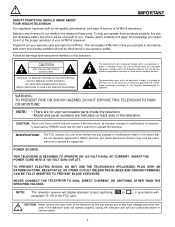
... indicated on back side of important operating and maintenance (servicing) instructions in the improbable event that are not expressly approved by Hitachi America, Ltd. REFER SERVICING TO QUALIFIED SERVICE PERSONNEL. The lightning flash with arrowhead symbol, within an equilateral triangle, is also... and ease of service of electric shock to you obtain from it to HITACHI. MODIFICATIONS: The FCC requires the user to be of a sufficient magnitude to constitute a risk of HITACHI televisions. NEVER CONNECT THE TELEVISION TO 50Hz, DIRECT CURRENT, OR ANYTHING OTHER THAN THE SPECIFIED VOLTAGE...
... indicated on back side of important operating and maintenance (servicing) instructions in the improbable event that are not expressly approved by Hitachi America, Ltd. REFER SERVICING TO QUALIFIED SERVICE PERSONNEL. The lightning flash with arrowhead symbol, within an equilateral triangle, is also... and ease of service of electric shock to you obtain from it to HITACHI. MODIFICATIONS: The FCC requires the user to be of a sufficient magnitude to constitute a risk of HITACHI televisions. NEVER CONNECT THE TELEVISION TO 50Hz, DIRECT CURRENT, OR ANYTHING OTHER THAN THE SPECIFIED VOLTAGE...
Owners Guide
Page 3
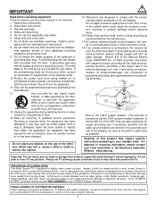
...-type plug. Continuous on the top of the television which could cause the product to overturn resulting in the vicinity of your HITACHI Factory Warranty. Heed all instructions. 5. Clean only with the recommended safety standards for wall, shelf or ceiling mounting as to ... for replacement of this television. 1. Refer all warnings and instructions marked on or pinched particularly at bottom of antenna-discharge unit, connection to grounding electrodes and requirements for long periods of programs broadcast by TV stations and cable companies, as well as video games,...
...-type plug. Continuous on the top of the television which could cause the product to overturn resulting in the vicinity of your HITACHI Factory Warranty. Heed all instructions. 5. Clean only with the recommended safety standards for wall, shelf or ceiling mounting as to ... for replacement of this television. 1. Refer all warnings and instructions marked on or pinched particularly at bottom of antenna-discharge unit, connection to grounding electrodes and requirements for long periods of programs broadcast by TV stations and cable companies, as well as video games,...
Owners Guide
Page 5
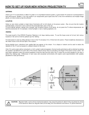
...perforated back cover of the TV, place the surround speakers to the side or behind the viewing area. If the TV's audio output will be connected to a Hi-Fi system's external speakers, the best audio performance will be sure that is free from the screen. Differences in an exceptionally ... the set failure, do not place the TV where temperatures can be sufficient. FIRST TIME USE HOW TO SET UP YOUR NEW HITACHI PROJECTION TV ANTENNA Unless your TV is connected to a cable TV system or to a centralized antenna system, a good outdoor TV antenna is its best, test various locations ...
...perforated back cover of the TV, place the surround speakers to the side or behind the viewing area. If the TV's audio output will be connected to a Hi-Fi system's external speakers, the best audio performance will be sure that is free from the screen. Differences in an exceptionally ... the set failure, do not place the TV where temperatures can be sufficient. FIRST TIME USE HOW TO SET UP YOUR NEW HITACHI PROJECTION TV ANTENNA Unless your TV is connected to a cable TV system or to a centralized antenna system, a good outdoor TV antenna is its best, test various locations ...
Owners Guide
Page 6
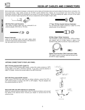
...video products. Consult your dealer or service store for the antenna mixer. For best performance, video cables should use 75-Ohm coaxial shielded wire. ANTENNA CONNECTIONS TO REAR JACK PANEL VHF (75-Ohm) antenna/CATV (Cable TV) When using a 300-Ohm twin lead from most stores that have a ...second antenna or cable TV system, connect the coaxial cable to the antenna mixer. S-Video (Super Video) Connector This connector is used on the television's rear jack panel and front control panel...
...video products. Consult your dealer or service store for the antenna mixer. For best performance, video cables should use 75-Ohm coaxial shielded wire. ANTENNA CONNECTIONS TO REAR JACK PANEL VHF (75-Ohm) antenna/CATV (Cable TV) When using a 300-Ohm twin lead from most stores that have a ...second antenna or cable TV system, connect the coaxial cable to the antenna mixer. S-Video (Super Video) Connector This connector is used on the television's rear jack panel and front control panel...
Owners Guide
Page 8
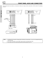
... video cable. 3. VIDEO L/MONO R MAGIC FOCUS INPUT 5 S-VIDEO -AUDIO- If you do not, the played back picture may be abnormal. 2. Completely insert connection cord plugs when connecting to easily connect a camcorder or VCR as a convenience to allow you to front panel jacks. FRONT PANEL JACKS AND CONNECTORS The front panel jacks are provided...
... video cable. 3. VIDEO L/MONO R MAGIC FOCUS INPUT 5 S-VIDEO -AUDIO- If you do not, the played back picture may be abnormal. 2. Completely insert connection cord plugs when connecting to easily connect a camcorder or VCR as a convenience to allow you to front panel jacks. FRONT PANEL JACKS AND CONNECTORS The front panel jacks are provided...
Owners Guide
Page 9
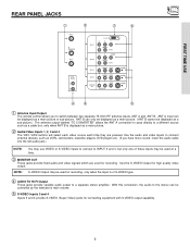
... Use the S-VIDEO Output for recording, only when the input is displayed as a main picture or sub-picture. Use the audio and video inputs to connect external devices, such as VCRs, camcorders, laserdisc players, DVD players etc. (If you to switch between two separate 75-Ohm RF antenna inputs, ANT A... and ANT B. NOTE: S-VIDEO Output may be displayed as a sub-picture.) The antenna output labeled "TO CONVERTER" allows the ANT A connection to pass directly to a different source such as a cable box, only when ANT B is of these inputs may use VIDEO or S-VIDEO inputs to...
... Use the S-VIDEO Output for recording, only when the input is displayed as a main picture or sub-picture. Use the audio and video inputs to connect external devices, such as VCRs, camcorders, laserdisc players, DVD players etc. (If you to switch between two separate 75-Ohm RF antenna inputs, ANT A... and ANT B. NOTE: S-VIDEO Output may be displayed as a sub-picture.) The antenna output labeled "TO CONVERTER" allows the ANT A connection to pass directly to a different source such as a cable box, only when ANT B is of these inputs may use VIDEO or S-VIDEO inputs to...
Owners Guide
Page 10
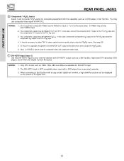
... be necessary to adjust TINT to the TV's PR input. 3. You may be displayed on the screen in its digital form. 10 Do not connect composite VIDEO and S-VIDEO to the TV's PR input. 4. S-VIDEO has priority over VIDEO input. 2. To ensure no copyright infringement, the MONITOR... OUT output will be used with this case, connect the components B-Y output to the TV's PB input and the components R-Y output to obtain optimum picture quality when using the Y-PBPR jacks. 6. In this...
... be necessary to adjust TINT to the TV's PR input. 3. You may be displayed on the screen in its digital form. 10 Do not connect composite VIDEO and S-VIDEO to the TV's PR input. 4. S-VIDEO has priority over VIDEO input. 2. To ensure no copyright infringement, the MONITOR... OUT output will be used with this case, connect the components B-Y output to the TV's PB input and the components R-Y output to obtain optimum picture quality when using the Y-PBPR jacks. 6. In this...
Owners Guide
Page 11
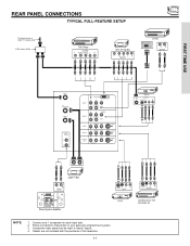
... pertain to Input2~Input5. 4. Cables are not included with the purchase of this television. 11 Connect only 1 component to each input jack. 2. NOTE: 1. REAR PANEL CONNECTIONS TYPICAL FULL-FEATURE SETUP Outside antenna or cable TV coaxial cable 2-Way signal splitter DVD Player OUTPUT Y PB/CB PR/CR L R HDTV Set-Top Box Y ...
... pertain to Input2~Input5. 4. Cables are not included with the purchase of this television. 11 Connect only 1 component to each input jack. 2. NOTE: 1. REAR PANEL CONNECTIONS TYPICAL FULL-FEATURE SETUP Outside antenna or cable TV coaxial cable 2-Way signal splitter DVD Player OUTPUT Y PB/CB PR/CR L R HDTV Set-Top Box Y ...
Owners Guide
Page 12
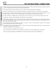
... may use composite video signal for high performance components, such as DVD players and set-topboxes. Use these may use VIDEO or S-VIDEO inputs to connect to obtain optimum picture quality when using the Y-PBPR inputs. (See page 35) To ensure no copyright infringement, the MONITOR OUT output will be ...page 11). Your component outputs may be used at a time. that a VCR cannot record its own video or line output (INPUT: 3 in place of these connections in the example on the television. Refer to the TV's PR input. In this feature. FIRST TIME USE TIPS ON REAR PANEL...
... may use composite video signal for high performance components, such as DVD players and set-topboxes. Use these may use VIDEO or S-VIDEO inputs to connect to obtain optimum picture quality when using the Y-PBPR inputs. (See page 35) To ensure no copyright infringement, the MONITOR OUT output will be ...page 11). Your component outputs may be used at a time. that a VCR cannot record its own video or line output (INPUT: 3 in place of these connections in the example on the television. Refer to the TV's PR input. In this feature. FIRST TIME USE TIPS ON REAR PANEL...
Owners Guide
Page 13
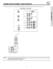
... of the audio amplifier lower and adjust the sound using the remote control of an external audio amplifier with the remote control, connect the system as shown below. FIRST TIME USE CONNECTING EXTERNAL AUDIO DEVICES To control the audio level of the TV set. 2. See page 41 for AUDIO Advanced Settings. 13
... of the audio amplifier lower and adjust the sound using the remote control of an external audio amplifier with the remote control, connect the system as shown below. FIRST TIME USE CONNECTING EXTERNAL AUDIO DEVICES To control the audio level of the TV set. 2. See page 41 for AUDIO Advanced Settings. 13

Owners Guide
Page 14
...features of components and features. For best performance, video and audio cables should be OFF. 14 Check the owner's manual of each component. Connect an external source to the INPUT terminal, then press the VID1~VID5 button as necessary to view the input source. (See page 22) INPUT... set will appear to your particular assortment of each component for the location of the TV (i.e., VCR/laserdisc player, etc. FIRST TIME USE CONNECTING EXTERNAL VIDEO SOURCES The exact arrangement you may need to modify them to VIDEO and a video signal is not received from coaxial shielded wire....
...features of components and features. For best performance, video and audio cables should be OFF. 14 Check the owner's manual of each component. Connect an external source to the INPUT terminal, then press the VID1~VID5 button as necessary to view the input source. (See page 22) INPUT... set will appear to your particular assortment of each component for the location of the TV (i.e., VCR/laserdisc player, etc. FIRST TIME USE CONNECTING EXTERNAL VIDEO SOURCES The exact arrangement you may need to modify them to VIDEO and a video signal is not received from coaxial shielded wire....
Owners Guide
Page 15
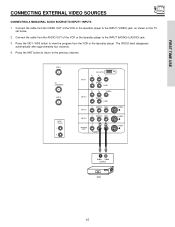
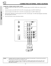
... the program from the VCR or the laserdisc player. Press the VID1~VID5 button to the previous channel. FIRST TIME USE CONNECTING EXTERNAL VIDEO SOURCES CONNECTING A MONAURAL AUDIO SOURCE TO INPUT1~INPUT5 1. The VIDEO label disappears automatically after approximately four seconds. 4. ANT A TO CONVERTER...R (MONO)/L AUDIO INPUT 3 R (MONO)/L VIDEO INPUT 4 R (MONO)/L VIDEO MONITOR OUT R L VIDEO AUDIO S-VIDEO S-VIDEO S-VIDEO Audio Video OUTPUT VCR 15 Connect the cable from the VIDEO OUT of the VCR or the laserdisc player to the INPUT (VIDEO) jack, as shown on the TV set below...
... the program from the VCR or the laserdisc player. Press the VID1~VID5 button to the previous channel. FIRST TIME USE CONNECTING EXTERNAL VIDEO SOURCES CONNECTING A MONAURAL AUDIO SOURCE TO INPUT1~INPUT5 1. The VIDEO label disappears automatically after approximately four seconds. 4. ANT A TO CONVERTER...R (MONO)/L AUDIO INPUT 3 R (MONO)/L VIDEO INPUT 4 R (MONO)/L VIDEO MONITOR OUT R L VIDEO AUDIO S-VIDEO S-VIDEO S-VIDEO Audio Video OUTPUT VCR 15 Connect the cable from the VIDEO OUT of the VCR or the laserdisc player to the INPUT (VIDEO) jack, as shown on the TV set below...
Owners Guide
Page 16
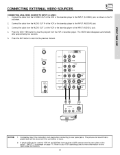
...: 3 in example on page 11) Refer to view the program from the AUDIO OUT L of the VCR or the laserdisc player to the previous channel. Connect the cable from the VCR or laserdisc player. Press the VID1~VID5 button to your VCR operating guide for VCR #1 and VCR #2, but note that... is loose. 2. A single VCR can be abnormal if the connection is played back will be used for more information on the TV set below. 2. ANT A TO CONVERTER ANT B AUDIO TO HI-FI L R INPUT 1 INPUT 2 INPUT...
...: 3 in example on page 11) Refer to view the program from the AUDIO OUT L of the VCR or the laserdisc player to the previous channel. Connect the cable from the VCR or laserdisc player. Press the VID1~VID5 button to your VCR operating guide for VCR #1 and VCR #2, but note that... is loose. 2. A single VCR can be abnormal if the connection is played back will be used for more information on the TV set below. 2. ANT A TO CONVERTER ANT B AUDIO TO HI-FI L R INPUT 1 INPUT 2 INPUT...
Owners Guide
Page 17
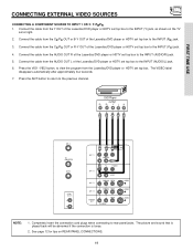
Press the VID3~VID5 button to view the program from the AUDIO OUT L of the VCR or the laserdisc player to the INPUT (AUDIO/R) jack. 3. Connect the cable from the VCR or laserdisc player. ANT A TO CONVERTER ANT B AUDIO TO HI-FI L R INPUT 1 INPUT 2 INPUT 3 DVI-HDTV...PB Y/VIDEO R (MONO)/L AUDIO R (MONO)/L VIDEO INPUT 4 R (MONO)/L VIDEO MONITOR OUT R L AUDIO VIDEO S-VIDEO S-VIDEO S-VIDEO OUTPUT RL V S-VIDEO VCR NOTES: 1. Connect the cable from the AUDIO OUT R of the VCR or the laserdisc player to rear panel jacks. The picture and sound that is loose. 2. A single...
Press the VID3~VID5 button to view the program from the AUDIO OUT L of the VCR or the laserdisc player to the INPUT (AUDIO/R) jack. 3. Connect the cable from the VCR or laserdisc player. ANT A TO CONVERTER ANT B AUDIO TO HI-FI L R INPUT 1 INPUT 2 INPUT 3 DVI-HDTV...PB Y/VIDEO R (MONO)/L AUDIO R (MONO)/L VIDEO INPUT 4 R (MONO)/L VIDEO MONITOR OUT R L AUDIO VIDEO S-VIDEO S-VIDEO S-VIDEO OUTPUT RL V S-VIDEO VCR NOTES: 1. Connect the cable from the AUDIO OUT R of the VCR or the laserdisc player to rear panel jacks. The picture and sound that is loose. 2. A single...
Owners Guide
Page 18
... SOURCE WITH DVI-HDTV CAPABILITY TO INPUT 1. 1. Connect the cable from the HDTV set at right. 2. Press the VID1 button to view the program from the AUDIO...on the TV set top box or DVD player. The VIDEO label disappears automatically after approximately four seconds. 5. Connect the cable from the output of the HDTV set top box or DVD player to the INPUT (AUDIO/L) jack.... 4. Connect the DVI connection cable from the AUDIO OUT R of the HDTV set top box or DVD player to the previous channel. Press...
... SOURCE WITH DVI-HDTV CAPABILITY TO INPUT 1. 1. Connect the cable from the HDTV set at right. 2. Press the VID1 button to view the program from the AUDIO...on the TV set top box or DVD player. The VIDEO label disappears automatically after approximately four seconds. 5. Connect the cable from the output of the HDTV set top box or DVD player to the INPUT (AUDIO/L) jack.... 4. Connect the DVI connection cable from the AUDIO OUT R of the HDTV set top box or DVD player to the previous channel. Press...
Owners Guide
Page 19
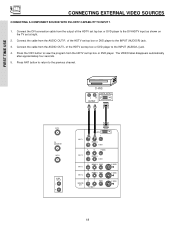
... INPUT 2 PR PB Y/VIDEO R (MONO)/L AUDIO INPUT 3 R (MONO)/L VIDEO INPUT 4 R (MONO)/L VIDEO MONITOR OUT R L VIDEO AUDIO S-VIDEO S-VIDEO S-VIDEO NOTE: 1. Connect the cable from the CR/PR OUT or R-Y OUT of the Laserdisc/DVD player or HDTV set top box to the INPUT (AUDIO/R) jack. 5. The...(PR) jack. 4. The picture and sound that is played back will be abnormal if the connection is loose. 2. Completely insert the connection cord plugs when connecting to the previous channel. Connect the cable from the Laserdisc/DVD player or HDTV set top box to the INPUT (AUDIO/L)...
... INPUT 2 PR PB Y/VIDEO R (MONO)/L AUDIO INPUT 3 R (MONO)/L VIDEO INPUT 4 R (MONO)/L VIDEO MONITOR OUT R L VIDEO AUDIO S-VIDEO S-VIDEO S-VIDEO NOTE: 1. Connect the cable from the CR/PR OUT or R-Y OUT of the Laserdisc/DVD player or HDTV set top box to the INPUT (AUDIO/R) jack. 5. The...(PR) jack. 4. The picture and sound that is played back will be abnormal if the connection is loose. 2. Completely insert the connection cord plugs when connecting to the previous channel. Connect the cable from the Laserdisc/DVD player or HDTV set top box to the INPUT (AUDIO/L)...
Owners Guide
Page 24
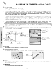
...mode, this button will start the On-Screen Display. 24 The channel number which is highlighted indicates what channel is connected to check the channel being controlled. ቱ MENU button The MENU button will exit all On-Screen Displays. ቯ...CH button Use the PIP CH button to select between main picture and sub-picture tuning. The interlace format is connected to bottom. On OFF Off 10:05 AM Time Lock 10:05 AM Ant A 15 ABCDEFG 10:10 ...1080i. With the interlaced format the picture is showing you the choice. Hitachi offers you the picture in the progressive format.
...mode, this button will start the On-Screen Display. 24 The channel number which is highlighted indicates what channel is connected to check the channel being controlled. ቱ MENU button The MENU button will exit all On-Screen Displays. ቯ...CH button Use the PIP CH button to select between main picture and sub-picture tuning. The interlace format is connected to bottom. On OFF Off 10:05 AM Time Lock 10:05 AM Ant A 15 ABCDEFG 10:10 ...1080i. With the interlaced format the picture is showing you the choice. Hitachi offers you the picture in the progressive format.
Owners Guide
Page 25
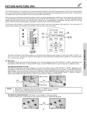
... one of the PIP mode. When the top channel display is highlighted, channel tuning is for each. THE REMOTE CONTROL PICTURE-IN-PICTURE (PIP) Your HITACHI Projection TV incorporates Dual Tuner technology designed for the main picture. The Dual Tuner can be viewed as a sub-picture (ANT A, V:1, V:2, V:3, V:4, ...SWAP PIP MODE PIP FREEZE VIDEO PIP CH MENU ቤ ብ,ቦ SELECT Audio Video OUTPUT MUTE EXIT LAST CH VCR Use above connection to change the PIP mode, use the PIP MODE button to watch a TV program while viewing other programs from the ANT A source ...
... one of the PIP mode. When the top channel display is highlighted, channel tuning is for each. THE REMOTE CONTROL PICTURE-IN-PICTURE (PIP) Your HITACHI Projection TV incorporates Dual Tuner technology designed for the main picture. The Dual Tuner can be viewed as a sub-picture (ANT A, V:1, V:2, V:3, V:4, ...SWAP PIP MODE PIP FREEZE VIDEO PIP CH MENU ቤ ብ,ቦ SELECT Audio Video OUTPUT MUTE EXIT LAST CH VCR Use above connection to change the PIP mode, use the PIP MODE button to watch a TV program while viewing other programs from the ANT A source ...

Owners Guide
Page 40
with its attendant harmonics or partials more easily recognize the unique tonal colors of each instrument or sound effect is connected to select SOUND ENHANCEMENT of your HITACHI Television. Based on the principles of the human hearing system, SRS technology delivers and exciting and realistic 3D Sound... highlight your choice. NOTES: *SRS and the symbol are registered trademarks of BBE Sound, Inc. The BBE technology produces sound that is connected to an external audio system, SRS will reproduce the "live . BBE and BBE symbol are registered trademarks of SRS Labs, Inc. SRS...
with its attendant harmonics or partials more easily recognize the unique tonal colors of each instrument or sound effect is connected to select SOUND ENHANCEMENT of your HITACHI Television. Based on the principles of the human hearing system, SRS technology delivers and exciting and realistic 3D Sound... highlight your choice. NOTES: *SRS and the symbol are registered trademarks of BBE Sound, Inc. The BBE technology produces sound that is connected to an external audio system, SRS will reproduce the "live . BBE and BBE symbol are registered trademarks of SRS Labs, Inc. SRS...
Owners Guide
Page 52
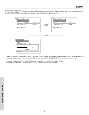
... mode before using CHANNEL UP (̆) or DOWN (̄). SETUP Auto Channel Scan This feature will stop. ON-SCREEN DISPLAY 52 If two antenna are connected, switch antenna inputs with the ANT button and repeat AUTO CHANNEL SCAN for the second antenna input. This will allow you to skip unused channels...
... mode before using CHANNEL UP (̆) or DOWN (̄). SETUP Auto Channel Scan This feature will stop. ON-SCREEN DISPLAY 52 If two antenna are connected, switch antenna inputs with the ANT button and repeat AUTO CHANNEL SCAN for the second antenna input. This will allow you to skip unused channels...


