
User Guide
Page 11
..., use the scroll bar to receive driver and software alerts, proactive change notifications (PCNs), the HP newsletter, customer advisories, and more. Definitions for HP Workstations include information about the operating system, power supply, memory, CPU, and many other system components. Subscriber's Choice is an HP program that allows you to sign up at http://www...
..., use the scroll bar to receive driver and software alerts, proactive change notifications (PCNs), the HP newsletter, customer advisories, and more. Definitions for HP Workstations include information about the operating system, power supply, memory, CPU, and many other system components. Subscriber's Choice is an HP program that allows you to sign up at http://www...

User Guide
Page 14
HP Z440 Workstation rear panel components 1 Power supply Built-In Self-Test (BIST) LED 8 Audio line-in jack (blue) 2 PS/2 keyboard connector (purple) 9 PCI/PCIe card slots 3 PS/2 mouse connector (green) 10 Power cord connector 4 USB 2.0 ports (2, black) 11 Universal chassis clamp opening 5 USB 3.0 ports (4, blue) 12 Padlock loop 6 AMT-enabled RJ-45 (network) jack (orange) 13 Security slot 7 Audio line-out jack (light green) 6 Chapter 2 Workstation features
HP Z440 Workstation rear panel components 1 Power supply Built-In Self-Test (BIST) LED 8 Audio line-in jack (blue) 2 PS/2 keyboard connector (purple) 9 PCI/PCIe card slots 3 PS/2 mouse connector (green) 10 Power cord connector 4 USB 2.0 ports (2, black) 11 Universal chassis clamp opening 5 USB 3.0 ports (4, blue) 12 Padlock loop 6 AMT-enabled RJ-45 (network) jack (orange) 13 Security slot 7 Audio line-out jack (light green) 6 Chapter 2 Workstation features

User Guide
Page 16
HP Z640 Workstation rear panel components 1 Power supply Built-In Self-Test (BIST) LED 7 AMT-enabled network jack (orange) 2 Rear power button 8 Audio line-out jack (green) 3 PS/2 keyboard connector (purple) 9 Audio line-in jack (blue) 4 PS/2 mouse connector (light green) 10 PCI/PCIe card slots 5 USB 2.0 ports (2, black) 11 Power cord connector 6 USB 3.0 ports (4, blue) 12 Security slot 8 Chapter 2 Workstation features
HP Z640 Workstation rear panel components 1 Power supply Built-In Self-Test (BIST) LED 7 AMT-enabled network jack (orange) 2 Rear power button 8 Audio line-out jack (green) 3 PS/2 keyboard connector (purple) 9 Audio line-in jack (blue) 4 PS/2 mouse connector (light green) 10 PCI/PCIe card slots 5 USB 2.0 ports (2, black) 11 Power cord connector 6 USB 3.0 ports (4, blue) 12 Security slot 8 Chapter 2 Workstation features

User Guide
Page 18
HP Z840 Workstation rear panel components 1 Power supply Built-In Self-Test (BIST) LED 8 2 Rear power button 9 3 Serial connector (teal blue) 10 4 PS/2 keyboard connector (purple) 11 5 PS/2 mouse connector (light green) 12 6 Audio line-out jack (green) 13 7 Audio line-in jack (blue) USB 2.0 ports (2, black) USB 3.0 ports (4, blue) Network jacks (2, orange) Bottom connector is AMT enabled PCI/PCIe card slots Power cord connector Security slot 10 Chapter 2 Workstation features
HP Z840 Workstation rear panel components 1 Power supply Built-In Self-Test (BIST) LED 8 2 Rear power button 9 3 Serial connector (teal blue) 10 4 PS/2 keyboard connector (purple) 11 5 PS/2 mouse connector (light green) 12 6 Audio line-out jack (green) 13 7 Audio line-in jack (blue) USB 2.0 ports (2, black) USB 3.0 ports (4, blue) Network jacks (2, orange) Bottom connector is AMT enabled PCI/PCIe card slots Power cord connector Security slot 10 Chapter 2 Workstation features

User Guide
Page 21
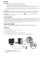
... included with a 1125 W power supply might require more power than the typical office environment can supply. The grounding pin is easily accessible. • Disconnect power from the workstation by unplugging the power cord from the AC outlet (not by unplugging the power cord from the workstation). •...; Plug the cord into an AC outlet. NOTE: An HP Z840 Workstation ...
... included with a 1125 W power supply might require more power than the typical office environment can supply. The grounding pin is easily accessible. • Disconnect power from the workstation by unplugging the power cord from the AC outlet (not by unplugging the power cord from the workstation). •...; Plug the cord into an AC outlet. NOTE: An HP Z840 Workstation ...
User Guide
Page 42
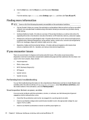
includes information on RTC batteries, memory, and power supply. ● Maintenance and Service Guide (English only)-Provides information on parts removal and replacement, troubleshooting, Desktop Management, setup utilities, safety, routine ... electrical outlet. ● Check to the more complex. Steps include: ● Visual inspection ● Blink or beep codes ● HP PC Hardware Diagnostics ● HP Support ● System restore ● System recovery Performing basic troubleshooting You can find troubleshooting information in the comprehensive Maintenance and Service Guide (...
includes information on RTC batteries, memory, and power supply. ● Maintenance and Service Guide (English only)-Provides information on parts removal and replacement, troubleshooting, Desktop Management, setup utilities, safety, routine ... electrical outlet. ● Check to the more complex. Steps include: ● Visual inspection ● Blink or beep codes ● HP PC Hardware Diagnostics ● HP Support ● System restore ● System recovery Performing basic troubleshooting You can find troubleshooting information in the comprehensive Maintenance and Service Guide (...
Workstation Quick Reference Card
Page 2
... mechanical safety information. Product description This product is an important safety feature. The Safety & Comfort Guide is easily accessible at http://www.hp.com/ergo. The AC adapter has a rating of electric shock or damage to the Regulatory, Safety and Environmental Notices provided with the ...client computer, or retail system and might feature a thin-panel display, TouchPad, processor, RAM, hard drive or solid state drive and internal power supply, and external AC adapter. The grounding pin is an All-in It describes proper workstation setup, and proper posture, health, and work ...
... mechanical safety information. Product description This product is an important safety feature. The Safety & Comfort Guide is easily accessible at http://www.hp.com/ergo. The AC adapter has a rating of electric shock or damage to the Regulatory, Safety and Environmental Notices provided with the ...client computer, or retail system and might feature a thin-panel display, TouchPad, processor, RAM, hard drive or solid state drive and internal power supply, and external AC adapter. The grounding pin is an All-in It describes proper workstation setup, and proper posture, health, and work ...
Safety & Comfort Guide User Guide
Page 6
......21 Mounting accessories ...22 Ventilation ...22 Water and moisture ...22 Grounded (earthed) products 22 Power sources ...22 Accessibility ...22 Voltage select switch ...22 Internal battery ...22 Power cords ...22 Protective attachment plug 23 Extension cord ...23 Overloading ...23 Cleaning ...23 Heat ...23......25 Floor-standing products ...25 Rack-mountable products 25 Precautions for products with hot-pluggable power supplies 25 Precautions for products with external television antenna connectors 26 Compatibility ...26 External television antenna grounding 26 Lightning protection ...26...
......21 Mounting accessories ...22 Ventilation ...22 Water and moisture ...22 Grounded (earthed) products 22 Power sources ...22 Accessibility ...22 Voltage select switch ...22 Internal battery ...22 Power cords ...22 Protective attachment plug 23 Extension cord ...23 Overloading ...23 Cleaning ...23 Heat ...23......25 Floor-standing products ...25 Rack-mountable products 25 Precautions for products with hot-pluggable power supplies 25 Precautions for products with external television antenna connectors 26 Compatibility ...26 External television antenna grounding 26 Lightning protection ...26...
Safety & Comfort Guide User Guide
Page 32
... enclosure covers or attempt to defeat the safety interlocks. ● Do not attempt to block airflow. For servers provided with safety interlocks that disable the power supply when the enclosure cover is removed. Failure to observe these precautions could result in servicing computer equipment and trained to the equipment. Hot surfaces Allow...
... enclosure covers or attempt to defeat the safety interlocks. ● Do not attempt to block airflow. For servers provided with safety interlocks that disable the power supply when the enclosure cover is removed. Failure to observe these precautions could result in servicing computer equipment and trained to the equipment. Hot surfaces Allow...

Safety & Comfort Guide User Guide
Page 33
... component at a time. The slide rails could pinch your fingers. ● Do not extend the components from the power supplies. Ensure that provides power to the rack. Due to the height and weight of the rack, HP recommends a minimum of two people to accomplish this task. ● Re working on a single rack or join...
... component at a time. The slide rails could pinch your fingers. ● Do not extend the components from the power supplies. Ensure that provides power to the rack. Due to the height and weight of the rack, HP recommends a minimum of two people to accomplish this task. ● Re working on a single rack or join...

Safety & Comfort Guide User Guide
Page 40
... 9 placement 9, 11, 12 support cover 24 N neck 1, 9, 17 O options 25 overheating warning iii, 24 P parent monitoring 18 pointing 7 positions 5 reclined 1 seated 1 standing 1 power cord 22 power lines 26 power supply 25 power surge 26 R rack-mountable products 25 radiation 21 rechargeable battery pack 24 reclined position 1 S safety interlocks 24 safety standards organizations 30 safety symbols...
... 9 placement 9, 11, 12 support cover 24 N neck 1, 9, 17 O options 25 overheating warning iii, 24 P parent monitoring 18 pointing 7 positions 5 reclined 1 seated 1 standing 1 power cord 22 power lines 26 power supply 25 power surge 26 R rack-mountable products 25 radiation 21 rechargeable battery pack 24 reclined position 1 S safety interlocks 24 safety standards organizations 30 safety symbols...

Maintenance and Service Guide
Page 7
... errors and warnings 65 DIMM installation guidelines 65 HP Z440 Workstation DIMM installation order 66 HP Z640 Workstation DIMM installation order 67 HP Z840 Workstation DIMM installation order 68 Power supply ...69 Power supply specifications 69 HP Z440 power supply specifications 69 HP Z640 power supply specifications 70 HP Z840 power supply specifications 71 Power consumption and heat dissipation 72 Resetting the power supply 72 System board ...72 System cabling ...73...
... errors and warnings 65 DIMM installation guidelines 65 HP Z440 Workstation DIMM installation order 66 HP Z640 Workstation DIMM installation order 67 HP Z840 Workstation DIMM installation order 68 Power supply ...69 Power supply specifications 69 HP Z440 power supply specifications 69 HP Z640 power supply specifications 70 HP Z840 power supply specifications 71 Power consumption and heat dissipation 72 Resetting the power supply 72 System board ...72 System cabling ...73...

Maintenance and Service Guide
Page 8
... ...88 Testing power supply ...88 Diagnostic codes and errors ...90 Diagnostic LED and audible (beep) codes 90 LED color definitions ...92 POST error messages ...92 5 Using HP PC Hardware Diagnostics (UEFI) ...97 Downloading HP PC Hardware Diagnostics (UEFI) to a USB device 97 Additional BIOS crisis recovery tool ...98 Using Remote HP PC Hardware Diagnostics (UEFI...
... ...88 Testing power supply ...88 Diagnostic codes and errors ...90 Diagnostic LED and audible (beep) codes 90 LED color definitions ...92 POST error messages ...92 5 Using HP PC Hardware Diagnostics (UEFI) ...97 Downloading HP PC Hardware Diagnostics (UEFI) to a USB device 97 Additional BIOS crisis recovery tool ...98 Using Remote HP PC Hardware Diagnostics (UEFI...

Maintenance and Service Guide
Page 13
HP Z440 Workstation rear panel components 1 Power supply Built-In Self-Test (BIST) LED 8 Audio line-out jack (light green) 2 Rear power button and LED 9 Audio line-in jack (blue) 3 PS/2 keyboard connector (purple) 10 PCI/PCIe card slots 4 PS/2 mouse connector (green) 11 Power cord connector 5 USB 2.0 ports (2, black) 12 Universal chassis clamp opening 6 USB 3.0 ports (4, blue) 13 Padlock loop 7 AMT-enabled RJ-45 (network) jack (orange) 14 Security slot HP Z440 Workstation components 3
HP Z440 Workstation rear panel components 1 Power supply Built-In Self-Test (BIST) LED 8 Audio line-out jack (light green) 2 Rear power button and LED 9 Audio line-in jack (blue) 3 PS/2 keyboard connector (purple) 10 PCI/PCIe card slots 4 PS/2 mouse connector (green) 11 Power cord connector 5 USB 2.0 ports (2, black) 12 Universal chassis clamp opening 6 USB 3.0 ports (4, blue) 13 Padlock loop 7 AMT-enabled RJ-45 (network) jack (orange) 14 Security slot HP Z440 Workstation components 3

Maintenance and Service Guide
Page 14
HP Z440 Workstation chassis components 1 Fan 2 Hard drive carrier 3 Hard drive, 3.5-inch 4 Side access panel 5 Memory fans 6 Heat sink 7 Processor 8 Memory module (DIMM) 9 Power supply 10 System board 11 Rear system fan and holder 12 Chassis 13 Speaker 14 PCIe card 15 Front bay filler (optional) 16 Optical drive, slim 17 Front bezel 4 Chapter 1 Hardware overview
HP Z440 Workstation chassis components 1 Fan 2 Hard drive carrier 3 Hard drive, 3.5-inch 4 Side access panel 5 Memory fans 6 Heat sink 7 Processor 8 Memory module (DIMM) 9 Power supply 10 System board 11 Rear system fan and holder 12 Chassis 13 Speaker 14 PCIe card 15 Front bay filler (optional) 16 Optical drive, slim 17 Front bezel 4 Chapter 1 Hardware overview

Maintenance and Service Guide
Page 16
HP Z440 Workstation specifications Processor technology Power supply Memory technology Intel Series C612 chipset: ● Support for the Intel Xeon Processor E5-1600 Series and E5-2600 Series ● Integrated 4-channel memory controller...performance ● Intel QuickPath Interconnect (QPI) connects processors and I/O controller with 8 PCIe lanes supported. For example, x16(8) means that the expansion slot is installed. HP Z440 Workstation system board architecture ● Dark blue slots are attached to CPU0 and available with CPU0. ● Purple and gray slots are attached to PCH...
HP Z440 Workstation specifications Processor technology Power supply Memory technology Intel Series C612 chipset: ● Support for the Intel Xeon Processor E5-1600 Series and E5-2600 Series ● Integrated 4-channel memory controller...performance ● Intel QuickPath Interconnect (QPI) connects processors and I/O controller with 8 PCIe lanes supported. For example, x16(8) means that the expansion slot is installed. HP Z440 Workstation system board architecture ● Dark blue slots are attached to CPU0 and available with CPU0. ● Purple and gray slots are attached to PCH...

Maintenance and Service Guide
Page 19
HP Z640 Workstation rear panel components 1 Power supply Built-In Self-Test (BIST) LED 7 AMT-enabled network jack (orange) 2 Rear power button and LED 8 Audio line-out jack (green) 3 PS/2 keyboard connector (purple) 9 Audio line-in jack (blue) 4 PS/2 mouse connector (light green) 10 PCI/PCIe card slots 5 USB 2.0 ports (2, black) 11 Power cord connector 6 USB 3.0 ports (4, blue) 12 Security slot HP Z640 Workstation components 9
HP Z640 Workstation rear panel components 1 Power supply Built-In Self-Test (BIST) LED 7 AMT-enabled network jack (orange) 2 Rear power button and LED 8 Audio line-out jack (green) 3 PS/2 keyboard connector (purple) 9 Audio line-in jack (blue) 4 PS/2 mouse connector (light green) 10 PCI/PCIe card slots 5 USB 2.0 ports (2, black) 11 Power cord connector 6 USB 3.0 ports (4, blue) 12 Security slot HP Z640 Workstation components 9

Maintenance and Service Guide
Page 20
HP Z640 Workstation chassis components 1 Hard drive carrier 2 Hard drive, 3.5-inch 3 Fan baffle 4 Processor Heatsink 5 Processor 6 Second processor module (optional) 7 Second processor (optional) 8 Memory module (DIMM) 9 System board 10 Side access panel 11 Card guide and front fan 12 Power supply 13 Chassis 14 PCI card 15 PCIe card 16 Rear system fan 17 Optical drive, slim 18 Front bezel 10 Chapter 1 Hardware overview
HP Z640 Workstation chassis components 1 Hard drive carrier 2 Hard drive, 3.5-inch 3 Fan baffle 4 Processor Heatsink 5 Processor 6 Second processor module (optional) 7 Second processor (optional) 8 Memory module (DIMM) 9 System board 10 Side access panel 11 Card guide and front fan 12 Power supply 13 Chassis 14 PCI card 15 PCIe card 16 Rear system fan 17 Optical drive, slim 18 Front bezel 10 Chapter 1 Hardware overview

Maintenance and Service Guide
Page 23
HP Z640 Workstation system board riser architecture ● Dark blue slots are attached to CPU0 and available with one processor, up to 9.6 GT/s ● 925 W Gold, 90% efficient, wide-ranging, active Power Factor Correction, two auxiliary dongles on two separate 12V rails, ERP 0.5W, Built-... to PCH. ● White slots are attached to 128 GB system memory (32 GB DIMMs) HP Z640 Workstation components 13 HP Z640 Workstation specifications Processor technology Power supply Memory technology Intel Series C612 chipset: ● Support for the Intel Xeon Processor E5-1600 Series and...
HP Z640 Workstation system board riser architecture ● Dark blue slots are attached to CPU0 and available with one processor, up to 9.6 GT/s ● 925 W Gold, 90% efficient, wide-ranging, active Power Factor Correction, two auxiliary dongles on two separate 12V rails, ERP 0.5W, Built-... to PCH. ● White slots are attached to 128 GB system memory (32 GB DIMMs) HP Z640 Workstation components 13 HP Z640 Workstation specifications Processor technology Power supply Memory technology Intel Series C612 chipset: ● Support for the Intel Xeon Processor E5-1600 Series and...

Maintenance and Service Guide
Page 26
HP Z840 Workstation rear panel components 1 Power supply Built-In Self-Test (BIST) LED 8 2 Rear power button 9 3 Serial connector (teal blue) 10 4 PS/2 keyboard connector (purple) 11 5 PS/2 mouse connector (light green) 12 6 Audio line-out jack (green) 13 7 Audio line-in jack (blue) USB 2.0 ports (2, black) USB 3.0 ports (4, blue) Network jacks (2, orange) Bottom connector is AMT enabled PCIe card slots Power cord connector Security slot 16 Chapter 1 Hardware overview
HP Z840 Workstation rear panel components 1 Power supply Built-In Self-Test (BIST) LED 8 2 Rear power button 9 3 Serial connector (teal blue) 10 4 PS/2 keyboard connector (purple) 11 5 PS/2 mouse connector (light green) 12 6 Audio line-out jack (green) 13 7 Audio line-in jack (blue) USB 2.0 ports (2, black) USB 3.0 ports (4, blue) Network jacks (2, orange) Bottom connector is AMT enabled PCIe card slots Power cord connector Security slot 16 Chapter 1 Hardware overview


