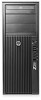
HP Z210 CMT Workstation Maintenance and Service Guide
Page 158
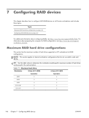
...topics: Topics Maximum RAID hard drive configurations on page 146 Configuring SATA RAID devices on HP workstations for RAID configuration, see http://www.hp.com/support/RAID_FAQs. Maximum RAID hard drive configurations This section lists the maximum number of... hard drives as discussed in cards and JBODs. Table 7-1 Maximum hard drives Workstation 8.5mm (3.5") SATA hard drive 6.3mm (2.5") SATA hard drive Z800 5 6 Z600 3 4 Z400 4 4 Z210 CMT 3 3 Z210 SFF ...
...topics: Topics Maximum RAID hard drive configurations on page 146 Configuring SATA RAID devices on HP workstations for RAID configuration, see http://www.hp.com/support/RAID_FAQs. Maximum RAID hard drive configurations This section lists the maximum number of... hard drives as discussed in cards and JBODs. Table 7-1 Maximum hard drives Workstation 8.5mm (3.5") SATA hard drive 6.3mm (2.5") SATA hard drive Z800 5 6 Z600 3 4 Z400 4 4 Z210 CMT 3 3 Z210 SFF ...
Hardware Support Matrix for Linux
Page 5
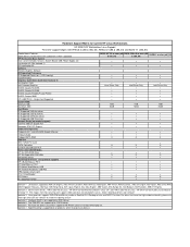
... have the Lightscribe functionality, please visit www.lightscribe.com for software to 2 SATA drives. footnote 5 - The Z200 SFF can support up to enable the labeling feature. Hardware Support Matrix for Current HP Linux Workstations HP Z200 SFF Workstation Linux Support First time support begins with RHEL5.4 (x86 & x86_64), RHEL6.0 (x86 & x86_64) and SLED 11...
... have the Lightscribe functionality, please visit www.lightscribe.com for software to 2 SATA drives. footnote 5 - The Z200 SFF can support up to enable the labeling feature. Hardware Support Matrix for Current HP Linux Workstations HP Z200 SFF Workstation Linux Support First time support begins with RHEL5.4 (x86 & x86_64), RHEL6.0 (x86 & x86_64) and SLED 11...

HP Workstations - CRU Dataport DX115 kit installation
Page 5
Figure 3 Removing the front bezel ENWW Step 2-Installing the DX115 case into the optical drive bay 5 If necessary, remove the bezel security screw, located beside the middle bezel release tab. Figure 2 Removing the bezel security screw b. Lift the release tabs (1), and then rotate the front bezel off the chassis (2). HP Z200 SFF computer To install a DX115 case in a Z200 SFF computer: 1. Remove the front bezel: a.
Figure 3 Removing the front bezel ENWW Step 2-Installing the DX115 case into the optical drive bay 5 If necessary, remove the bezel security screw, located beside the middle bezel release tab. Figure 2 Removing the bezel security screw b. Lift the release tabs (1), and then rotate the front bezel off the chassis (2). HP Z200 SFF computer To install a DX115 case in a Z200 SFF computer: 1. Remove the front bezel: a.

HP Z210 Workstation Series User Guide
Page 5
... ...2 Product support ...3 Product documentation ...4 Product diagnostics ...5 Product updates ...6 2 Workstation components 7 HP Z210 CMT Workstation components 7 HP Z210 CMT Workstation chassis components 8 HP Z210 CMT Workstation front panel components 9 HP Z210 CMT Workstation rear panel components 10 HP Z210 SFF Workstation components 11 HP Z210 SFF Workstation chassis components 11 HP Z210 SFF Workstation front panel components 12 HP Z210 SFF Workstation rear panel components 13 3 Setting up the workstation 14...
... ...2 Product support ...3 Product documentation ...4 Product diagnostics ...5 Product updates ...6 2 Workstation components 7 HP Z210 CMT Workstation components 7 HP Z210 CMT Workstation chassis components 8 HP Z210 CMT Workstation front panel components 9 HP Z210 CMT Workstation rear panel components 10 HP Z210 SFF Workstation components 11 HP Z210 SFF Workstation chassis components 11 HP Z210 SFF Workstation front panel components 12 HP Z210 SFF Workstation rear panel components 13 3 Setting up the workstation 14...
HP Z210 Workstation Series User Guide
Page 7
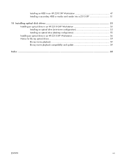
Installing an HDD in an HP Z210 SFF Workstation 47 Installing a secondary HDD or media card reader into a Z210 SFF 51 10 Installing optical disk drives 53 Installing an optical drive in an HP Z210 CMT Workstation 53 Installing an optical drive (mini-tower configuration 53 Installing an optical drive (desktop configuration 55 Installing an optical drive in an HP Z210 SFF Workstation 56 Notice for Blu-ray optical drives 59 Blu-ray movie playback 59 Blu-ray movie playback compatibility and update 59 Index ...60 ENWW vii
Installing an HDD in an HP Z210 SFF Workstation 47 Installing a secondary HDD or media card reader into a Z210 SFF 51 10 Installing optical disk drives 53 Installing an optical drive in an HP Z210 CMT Workstation 53 Installing an optical drive (mini-tower configuration 53 Installing an optical drive (desktop configuration 55 Installing an optical drive in an HP Z210 SFF Workstation 56 Notice for Blu-ray optical drives 59 Blu-ray movie playback 59 Blu-ray movie playback compatibility and update 59 Index ...60 ENWW vii

HP Z210 Workstation Series User Guide
Page 15
It includes these topics: Topics HP Z210 CMT Workstation components on page 7 HP Z210 SFF Workstation components on supported accessories and components for the computer, see http://partsurfer.hp.com. ENWW HP Z210 CMT Workstation components 7 For complete and current information on page 11 HP Z210 CMT Workstation components This section describes the HP Z210 Convertible Mini Tower (CMT) Workstation components, including front and rear panel connectors. 2 Workstation components This chapter describes workstation components.
It includes these topics: Topics HP Z210 CMT Workstation components on page 7 HP Z210 SFF Workstation components on supported accessories and components for the computer, see http://partsurfer.hp.com. ENWW HP Z210 CMT Workstation components 7 For complete and current information on page 11 HP Z210 CMT Workstation components This section describes the HP Z210 Convertible Mini Tower (CMT) Workstation components, including front and rear panel connectors. 2 Workstation components This chapter describes workstation components.
HP Z210 Workstation Series User Guide
Page 19
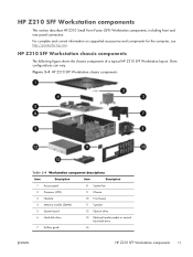
... components The following figure shows the chassis components of a typical HP Z210 SFF Workstation layout. Drive configurations can vary. Figure 2-4 HP Z210 SFF Workstation chassis components Table 2-4 Workstation component descriptions Item Description Item Description 1 Access panel 8... guide 14 ENWW HP Z210 SFF Workstation components 11 For complete and current information on supported accessories and components for the computer, see http://partsurfer.hp.com. HP Z210 SFF Workstation components This section describes HP Z210 Small Form Factor (SFF) Workstation components, ...
... components The following figure shows the chassis components of a typical HP Z210 SFF Workstation layout. Drive configurations can vary. Figure 2-4 HP Z210 SFF Workstation chassis components Table 2-4 Workstation component descriptions Item Description Item Description 1 Access panel 8... guide 14 ENWW HP Z210 SFF Workstation components 11 For complete and current information on supported accessories and components for the computer, see http://partsurfer.hp.com. HP Z210 SFF Workstation components This section describes HP Z210 Small Form Factor (SFF) Workstation components, ...

HP Z210 Workstation Series User Guide
Page 20
Figure 2-5 HP Z210 Workstation front panel Table 2-5 Front panel components Item Symbol Description 1 Optical drive 2 Optical drive activity light 3 Optical drive eject button 4 Power button 5 USB 2.0 ports (4) Item 6 7 ... microphone) Headphones connector 8 Hard drive activity light 9 Optional media card reader or second hard disk drive 12 Chapter 2 Workstation components ENWW Drive configurations can vary. HP Z210 SFF Workstation front panel components The following figure shows the front panel of an...
Figure 2-5 HP Z210 Workstation front panel Table 2-5 Front panel components Item Symbol Description 1 Optical drive 2 Optical drive activity light 3 Optical drive eject button 4 Power button 5 USB 2.0 ports (4) Item 6 7 ... microphone) Headphones connector 8 Hard drive activity light 9 Optional media card reader or second hard disk drive 12 Chapter 2 Workstation components ENWW Drive configurations can vary. HP Z210 SFF Workstation front panel components The following figure shows the front panel of an...
HP Z210 Workstation Series User Guide
Page 21
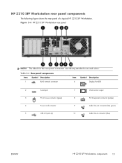
... panel components The following figure shows the rear panel of a typical HP Z210 SFF Workstation. Table 2-6 Rear panel components Item Symbol Description Item Symbol Description 1 RJ-45 network connector 6 Display Port (DP) 2 Serial port 7 VGA... PS/2 keyboard connector (purple) 4 Power cord connector 9 Audio line-out connector (lime green) 5 USB 2.0 ports (6) 10 Audio line-in connector (blue) ENWW HP Z210 SFF Workstation components 13 Figure 2-6 HP Z210 SFF Workstation rear panel NOTE: The labels for the rear panel connectors use industry-standard icons and colors.
... panel components The following figure shows the rear panel of a typical HP Z210 SFF Workstation. Table 2-6 Rear panel components Item Symbol Description Item Symbol Description 1 RJ-45 network connector 6 Display Port (DP) 2 Serial port 7 VGA... PS/2 keyboard connector (purple) 4 Power cord connector 9 Audio line-out connector (lime green) 5 USB 2.0 ports (6) 10 Audio line-in connector (blue) ENWW HP Z210 SFF Workstation components 13 Figure 2-6 HP Z210 SFF Workstation rear panel NOTE: The labels for the rear panel connectors use industry-standard icons and colors.
HP Z210 Workstation Series User Guide
Page 27
...interface to other graphics formats, including DVI-I . (See HP Z210 CMT Workstation rear panel components on page 10.) The HP Z210 SFF workstation provides rear-panel connectors for DisplayPort and VGA. (See HP Z210 SFF Workstation rear panel components on page 13.) Planning for additional... graphics card to monitor connectors on CPU configuration, some HP Z210 CMT and SFF workstations support Intel® HD Graphics (integrated graphics) with HP Z Workstations support two simultaneous display monitors (see http://www.hp.com/go/workstations for additional information about your workstation. ...
...interface to other graphics formats, including DVI-I . (See HP Z210 CMT Workstation rear panel components on page 10.) The HP Z210 SFF workstation provides rear-panel connectors for DisplayPort and VGA. (See HP Z210 SFF Workstation rear panel components on page 13.) Planning for additional... graphics card to monitor connectors on CPU configuration, some HP Z210 CMT and SFF workstations support Intel® HD Graphics (integrated graphics) with HP Z Workstations support two simultaneous display monitors (see http://www.hp.com/go/workstations for additional information about your workstation. ...

HP Z210 Workstation Series User Guide
Page 42
This section describes how to upright position (Z210 SFF) Optical drive Chassis locks Side access panel Remove front bezel * See the workstation Maintenance and Service Guide for chassis lock locations and operation instructions....access panel Expansion card (PCI/ Chassis locks PCIe) Side access panel Hard drive Chassis locks Side access panel Rotate front drive cage to upward position (Z210 SFF) Rotate power supply to prepare your workstation for component installation. 6 Preparing for component installation To facilitate the installation of components, several steps can be ...
This section describes how to upright position (Z210 SFF) Optical drive Chassis locks Side access panel Remove front bezel * See the workstation Maintenance and Service Guide for chassis lock locations and operation instructions....access panel Expansion card (PCI/ Chassis locks PCIe) Side access panel Hard drive Chassis locks Side access panel Rotate front drive cage to upward position (Z210 SFF) Rotate power supply to prepare your workstation for component installation. 6 Preparing for component installation To facilitate the installation of components, several steps can be ...

HP Z210 Workstation Series User Guide
Page 43
... the card retention clamp by pressing down at the green touch point to open it, then lift the slot cover from the chassis (2). Z210 SFF Lift the card retention clamp at the green touch points (1), and then lift the slot cover from the chassis. Raise the expansion card retention clamp... and remove the expansion card slot cover as shown in the following illustrations, if applicable. Z210 SFF Lift the side access panel handle (1), and remove the side access panel (2). 4. ENWW Preparing the workstation for component installation 35...
... the card retention clamp by pressing down at the green touch point to open it, then lift the slot cover from the chassis (2). Z210 SFF Lift the card retention clamp at the green touch points (1), and then lift the slot cover from the chassis. Raise the expansion card retention clamp... and remove the expansion card slot cover as shown in the following illustrations, if applicable. Z210 SFF Lift the side access panel handle (1), and remove the side access panel (2). 4. ENWW Preparing the workstation for component installation 35...
HP Z210 Workstation Series User Guide
Page 44
Lift the release tabs (1), and then rotate the front bezel off the chassis (2). 6. (HP Z210 SFF only) Rotate the front drive cage to the upright position. 36 Chapter 6 Preparing for component installation ENWW 5. (HP Z210 CMT only) Remove the front bezel as shown in the following illustration.
Lift the release tabs (1), and then rotate the front bezel off the chassis (2). 6. (HP Z210 SFF only) Rotate the front drive cage to the upright position. 36 Chapter 6 Preparing for component installation ENWW 5. (HP Z210 CMT only) Remove the front bezel as shown in the following illustration.

HP Z210 Workstation Series User Guide
Page 45
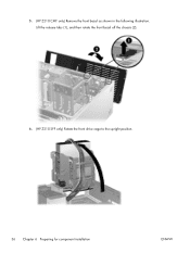
ENWW Preparing the workstation for the component installation procedures described in the chapters that follow. The workstation is now prepared for component installation 37 7. (HP Z210 SFF only) Rotate the power supply to its upright position.
ENWW Preparing the workstation for the component installation procedures described in the chapters that follow. The workstation is now prepared for component installation 37 7. (HP Z210 SFF only) Rotate the power supply to its upright position.
HP Z210 Workstation Series User Guide
Page 46
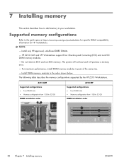
... configurations supported by the HP Z210 Workstations. The system will not boot and will produce a memory error. - NOTE: - For maximum performance, install DIMM memory modules in the order shown below. Z210 CMT Supported configurations ● Four DIMM slots ● Memory configuration from 1 GB to 32 GB DIMM installation order Z210 SFF Supported configurations ● Four...
... configurations supported by the HP Z210 Workstations. The system will not boot and will produce a memory error. - NOTE: - For maximum performance, install DIMM memory modules in the order shown below. Z210 CMT Supported configurations ● Four DIMM slots ● Memory configuration from 1 GB to 32 GB DIMM installation order Z210 SFF Supported configurations ● Four...
HP Z210 Workstation Series User Guide
Page 49
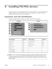
Z210 CMT Z210 SFF Slot description 1-PCIe2 - x16 3-PCIe2 - For example, x8(4) means that the expansion slot is mechanically a x8 length connector, with four PCIe lanes connected. x16(4) 5-PCIe2 - ... x16 designators describe the mechanical (physical) length of your system, PCI/PCIe devices such as graphics cards or audio cards can be installed in the HP Z210 Workstations. 8 Installing PCI/PCIe devices This section describes how to the expansion slot. Expansion card slot identification The following tables describe the expansion card slots...
Z210 CMT Z210 SFF Slot description 1-PCIe2 - x16 3-PCIe2 - For example, x8(4) means that the expansion slot is mechanically a x8 length connector, with four PCIe lanes connected. x16(4) 5-PCIe2 - ... x16 designators describe the mechanical (physical) length of your system, PCI/PCIe devices such as graphics cards or audio cards can be installed in the HP Z210 Workstations. 8 Installing PCI/PCIe devices This section describes how to the expansion slot. Expansion card slot identification The following tables describe the expansion card slots...
HP Z210 Workstation Series User Guide
Page 50
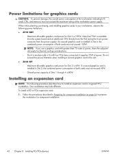
... four PCIe lanes connected; If a second graphics card is 80W. Installing an expansion card NOTE: The following power limitations: ● Z210 CMT ◦ Maximum allowable graphics card power for component installation. 42 Chapter 8 Installing PCI/PCIe devices ENWW Your workstation may look different...in your workstation, observe the following procedure describes how to prepare the workstation for Slot 2 is installed in this slot. ● Z210 SFF ◦ Maximum allowable graphics card power for Slot 2 is available from the system board and an additional 75W directly from the PSU...
... four PCIe lanes connected; If a second graphics card is 80W. Installing an expansion card NOTE: The following power limitations: ● Z210 CMT ◦ Maximum allowable graphics card power for component installation. 42 Chapter 8 Installing PCI/PCIe devices ENWW Your workstation may look different...in your workstation, observe the following procedure describes how to prepare the workstation for Slot 2 is installed in this slot. ● Z210 SFF ◦ Maximum allowable graphics card power for Slot 2 is available from the system board and an additional 75W directly from the PSU...

HP Z210 Workstation Series User Guide
Page 51
...). 5. Replace all components removed in the following illustration (1). ENWW Installing an expansion card 43 Figure 8-1 Installing an expansion card (Z210 CMT shown) 3. Connect all cards are seated. Close the retention clamp by rotating it downward (2) as shown in preparation for ...component installation. Figure 8-2 Closing the expansion card retention clamp (Z210 SFF) 4. NOTE: For the Z210 SFF Workstation, close the expansion slot retention clamp making sure all necessary power and interface cables to the card (follow ...
...). 5. Replace all components removed in the following illustration (1). ENWW Installing an expansion card 43 Figure 8-1 Installing an expansion card (Z210 CMT shown) 3. Connect all cards are seated. Close the retention clamp by rotating it downward (2) as shown in preparation for ...component installation. Figure 8-2 Closing the expansion card retention clamp (Z210 SFF) 4. NOTE: For the Z210 SFF Workstation, close the expansion slot retention clamp making sure all necessary power and interface cables to the card (follow ...
HP Z210 Workstation Series User Guide
Page 52
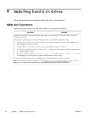
Z210 CMT Z210 SFF HDD bays are assigned using the Computer Setup (F10) Utility. The workstation typically ships with an HDD, but additional drives can be added to expand ... are pre-connected in the workstation based on the type of the additional drives. Refer to the workstation Maintenance and Service Guide at http://www.hp.com/support/workstation_manuals to permit easy installation. With additional HDDs installed, you have hard disk space for additional programs, data files, and backup. HDD configuration...
Z210 CMT Z210 SFF HDD bays are assigned using the Computer Setup (F10) Utility. The workstation typically ships with an HDD, but additional drives can be added to expand ... are pre-connected in the workstation based on the type of the additional drives. Refer to the workstation Maintenance and Service Guide at http://www.hp.com/support/workstation_manuals to permit easy installation. With additional HDDs installed, you have hard disk space for additional programs, data files, and backup. HDD configuration...
HP Z210 Workstation Series User Guide
Page 53
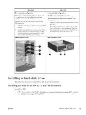
... primary (SATA Gen 3) hard disk drives to SATA ports zero and one ) support SATA Gen 3 (6 Gbit/sec). Follow the procedures described in an HP Z210 CMT Workstation To install an HDD: 1. The cables plug into the system board connectors in the following manner: ● SATA HDD cables plug into SATA... disk drive This section describes how to prepare the workstation for component installation. The cables plug into the system board connectors in the workstation. Z210 CMT Z210 SFF Drive and cable configuration Drive and cable configuration HDD bays are not labeled on the chassis.
... primary (SATA Gen 3) hard disk drives to SATA ports zero and one ) support SATA Gen 3 (6 Gbit/sec). Follow the procedures described in an HP Z210 CMT Workstation To install an HDD: 1. The cables plug into the system board connectors in the following manner: ● SATA HDD cables plug into SATA... disk drive This section describes how to prepare the workstation for component installation. The cables plug into the system board connectors in the workstation. Z210 CMT Z210 SFF Drive and cable configuration Drive and cable configuration HDD bays are not labeled on the chassis.


