
HP LaserJet P2015 - Software Technical Reference
Page 66
...is printed. To improve transfer, increase the transfer bias voltage. In this case, more extreme cases. ◦ Rough paper. The HP LaserJet P2015 printer has an electrostatic discharge brush where the paper separates from contact with the OPC drum. The range of increased transfer bias voltage if ... The engine has a humidity sensor and also checks the conductivity of the ETB in more transfer current is applied by the formatter. This setting increases transfer current. These adjustments can help find the best operating point. ● Toner. These adjustments can help...
...is printed. To improve transfer, increase the transfer bias voltage. In this case, more extreme cases. ◦ Rough paper. The HP LaserJet P2015 printer has an electrostatic discharge brush where the paper separates from contact with the OPC drum. The range of increased transfer bias voltage if ... The engine has a humidity sensor and also checks the conductivity of the ETB in more transfer current is applied by the formatter. This setting increases transfer current. These adjustments can help find the best operating point. ● Toner. These adjustments can help...

Service Manual
Page 7
... ...87 Duplexer tray (HP LaserJet P2015d, P2015dn, and P2015x printers only 89 Top cover ...90 Control panel ...95 Formatter ...97 Laser/scanner ...98 Memory-tag-reader assembly ...99 Duplex-drive PCA (HP LaserJet P2015d, P2015dn, and P2015x printers only 101 Fuser ...103 Fan ...103 Duplex-drive gears (HP LaserJet P2015d, P2015dn, and P2015x printers only 104 Duplex solenoid (HP LaserJet P2015d, P2015dn, and...
... ...87 Duplexer tray (HP LaserJet P2015d, P2015dn, and P2015x printers only 89 Top cover ...90 Control panel ...95 Formatter ...97 Laser/scanner ...98 Memory-tag-reader assembly ...99 Duplex-drive PCA (HP LaserJet P2015d, P2015dn, and P2015x printers only 101 Fuser ...103 Fan ...103 Duplex-drive gears (HP LaserJet P2015d, P2015dn, and P2015x printers only 104 Duplex solenoid (HP LaserJet P2015d, P2015dn, and...

Service Manual
Page 83
...WAIT or LSTR period until either returns to STBY or, if another print command was sent from the formatter, enters INTR. solenoid is turned off . After LSTR, the printer either a print command is sent from the drum surface and cleans the transfer roller. Forms the ... engine operations for printing. Clears potential from the formatter or the power is turned off . From the end of a print cartridge. Prepares the printer to receive print commands INTR (initial rotation) From the time of a print operation. Laser/scanner motor initial drive High-voltage control Detect presence...
...WAIT or LSTR period until either returns to STBY or, if another print command was sent from the formatter, enters INTR. solenoid is turned off . After LSTR, the printer either a print command is sent from the drum surface and cleans the transfer roller. Forms the ... engine operations for printing. Clears potential from the formatter or the power is turned off . From the end of a print cartridge. Prepares the printer to receive print commands INTR (initial rotation) From the time of a print operation. Laser/scanner motor initial drive High-voltage control Detect presence...

Service Manual
Page 84
The engine control system contains the following components: ● DC controller ● High-voltage PCA Figure 5-3 Engine control system 74 Chapter 5 Theory of operation ENWW Engine control system The engine control system coordinates all printer functions, according to commands sent from the formatter. It drives the laser/scanner system, the image-formation system, and the pickup/feed/ delivery system.
The engine control system contains the following components: ● DC controller ● High-voltage PCA Figure 5-3 Engine control system 74 Chapter 5 Theory of operation ENWW Engine control system The engine control system coordinates all printer functions, according to commands sent from the formatter. It drives the laser/scanner system, the image-formation system, and the pickup/feed/ delivery system.
Service Manual
Page 86
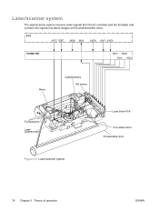
Laser/scanner system The laser/scanner system receives video signals from the dc controller and the formatter and converts the signals into latent images on the photosensitive drum. Figure 5-5 Laser/scanner system 76 Chapter 5 Theory of operation ENWW
Laser/scanner system The laser/scanner system receives video signals from the dc controller and the formatter and converts the signals into latent images on the photosensitive drum. Figure 5-5 Laser/scanner system 76 Chapter 5 Theory of operation ENWW
Service Manual
Page 87
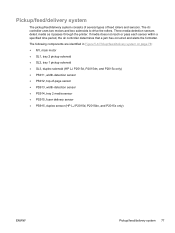
... page 78: ● M1, main motor ● SL1, tray 2 pickup solenoid ● SL2, tray 1 pickup solenoid ● SL3, duplex solenoid (HP LJ P2015d, P2015dn, and P2015x only) ● PS911, width-detection sensor ● PS912, top-of feed rollers and sensors. The dc controller uses two ... sensor within a specified time period, the dc controller determines that a jam has occurred and alerts the formatter. Three media-detection sensors detect media as it passes through the printer. Pickup/feed/delivery system The pickup/feed/delivery system consists of several types of -page sensor ●...
... page 78: ● M1, main motor ● SL1, tray 2 pickup solenoid ● SL2, tray 1 pickup solenoid ● SL3, duplex solenoid (HP LJ P2015d, P2015dn, and P2015x only) ● PS911, width-detection sensor ● PS912, top-of feed rollers and sensors. The dc controller uses two ... sensor within a specified time period, the dc controller determines that a jam has occurred and alerts the formatter. Three media-detection sensors detect media as it passes through the printer. Pickup/feed/delivery system The pickup/feed/delivery system consists of several types of -page sensor ●...

Service Manual
Page 93
6 Removal and replacement ● Introduction ● Before performing service ● Covers ● Control panel ● Formatter ● Laser/scanner ● Memory-tag-reader assembly ● Duplex-drive PCA (HP LaserJet P2015d, P2015dn, and P2015x printers only) ● Fuser ● Interlock assembly ● ECU ● Main motor ● Pickup and feed assemblies ● Main gear assembly/tray 2 pickup solenoid ● Print-cartridge door ENWW 83
6 Removal and replacement ● Introduction ● Before performing service ● Covers ● Control panel ● Formatter ● Laser/scanner ● Memory-tag-reader assembly ● Duplex-drive PCA (HP LaserJet P2015d, P2015dn, and P2015x printers only) ● Fuser ● Interlock assembly ● ECU ● Main motor ● Pickup and feed assemblies ● Main gear assembly/tray 2 pickup solenoid ● Print-cartridge door ENWW 83

Service Manual
Page 107
ENWW Formatter 97 Remove four screws (5). Remove the formatter. Formatter 1. Disconnect one cable (4) at the top of the formatter. 6. Disconnect one cable (1) at the bottom of the formatter. 3. Disconnect one flat, flexible cable (3) at the top of the formatter. 5. Figure 6-12 Removing the formatter 7. Also, do not straighten pre-folds in flat, flexible cables. 4. Remove the left-side cover. 2. CAUTION Do not fold flat, flexible cables. Disconnect one flat, flexible cable (2) at the bottom of the formatter.
ENWW Formatter 97 Remove four screws (5). Remove the formatter. Formatter 1. Disconnect one cable (4) at the top of the formatter. 6. Disconnect one cable (1) at the bottom of the formatter. 3. Disconnect one flat, flexible cable (3) at the top of the formatter. 5. Figure 6-12 Removing the formatter 7. Also, do not straighten pre-folds in flat, flexible cables. 4. Remove the left-side cover. 2. CAUTION Do not fold flat, flexible cables. Disconnect one flat, flexible cable (2) at the bottom of the formatter.
Service Manual
Page 109
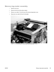
Memory-tag-reader assembly 1. Remove one cable (2) from the formatter. Disconnect one cable (1) from the printer chassis. 3. Figure 6-14 Removing the memory-tag-reader assembly (1 of the memory-tag-reader cover. 4. Remove the fan from the top of 2) ENWW Memory-tag-reader assembly 99 Remove all covers. 2.
Memory-tag-reader assembly 1. Remove one cable (2) from the formatter. Disconnect one cable (1) from the printer chassis. 3. Figure 6-14 Removing the memory-tag-reader assembly (1 of the memory-tag-reader cover. 4. Remove the fan from the top of 2) ENWW Memory-tag-reader assembly 99 Remove all covers. 2.
Service Manual
Page 117
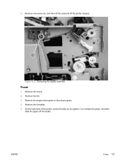
Remove the formatter. 5. Remove the fan. 3. ENWW Fuser 107 Remove the duplex-drive gears or face-down gears. 4. Remove one screw (2), and then lift the solenoid off the shafts. Figure 6-22 Removing the duplex solenoid Fuser 1. On the right side of the printer, press the tabs on two gears (1) to release the gears, and then slide the gears off the printer chassis. 5. Remove all covers. 2.
Remove the formatter. 5. Remove the fan. 3. ENWW Fuser 107 Remove the duplex-drive gears or face-down gears. 4. Remove one screw (2), and then lift the solenoid off the shafts. Figure 6-22 Removing the duplex solenoid Fuser 1. On the right side of the printer, press the tabs on two gears (1) to release the gears, and then slide the gears off the printer chassis. 5. Remove all covers. 2.
Service Manual
Page 129
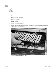
Remove cables from the cable clip under the feed plate (1), and then remove the feed plate by lifting it and pulling it straight back. Figure 6-34 Removing the ECU (1 of 7) ENWW ECU 119 Remove all covers. 2. Remove the formatter. 5. Remove the interlock assembly. 7. Remove the fuser. 6. Remove the fan. 3. Remove the duplex-drive gears. 4. ECU 1.
Remove cables from the cable clip under the feed plate (1), and then remove the feed plate by lifting it and pulling it straight back. Figure 6-34 Removing the ECU (1 of 7) ENWW ECU 119 Remove all covers. 2. Remove the formatter. 5. Remove the interlock assembly. 7. Remove the fuser. 6. Remove the fan. 3. Remove the duplex-drive gears. 4. ECU 1.

Service Manual
Page 132
Remove two screws (1) from the left side of 7) 122 Chapter 6 Removal and replacement ENWW Figure 6-37 Removing the ECU (4 of the printer, and then push the interlock cables and the formatter cable (2) through the hole in the chassis. 10.
Remove two screws (1) from the left side of 7) 122 Chapter 6 Removal and replacement ENWW Figure 6-37 Removing the ECU (4 of the printer, and then push the interlock cables and the formatter cable (2) through the hole in the chassis. 10.
Service Manual
Page 136
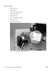
Remove the interlock assembly. 7. Main motor 1. Remove all covers. 2. Remove the ECU. 8. Remove the fuser. 6. Figure 6-41 Removing the main motor (1 of 2) 126 Chapter 6 Removal and replacement ENWW Remove the formatter. 5. Remove the duplex-drive gears. 4. Remove the fan. 3. Remove three screws (1).
Remove the interlock assembly. 7. Main motor 1. Remove all covers. 2. Remove the ECU. 8. Remove the fuser. 6. Figure 6-41 Removing the main motor (1 of 2) 126 Chapter 6 Removal and replacement ENWW Remove the formatter. 5. Remove the duplex-drive gears. 4. Remove the fan. 3. Remove three screws (1).

Service Manual
Page 148
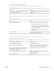
... turn on and the motor rotates, but the motor does not rotate. Replace the gear assembly. Replace the motor. The printer is defective. The formatter is unresponsive. Verify that it rotates freely. Cause Solution The print cartridge door is defective. The main motor is open.... effect. Media is defective. Reconnect the motor cable. The ECU is jammed in the printer chassis. Cause Solution The control panel cable is not mounted correctly in the paper path. Replace the formatter. 138 Chapter 7 Problem solving ENWW When turned on, the LEDs on . 2. Clear...
... turn on and the motor rotates, but the motor does not rotate. Replace the gear assembly. Replace the motor. The printer is defective. The formatter is unresponsive. Verify that it rotates freely. Cause Solution The print cartridge door is defective. The main motor is open.... effect. Media is defective. Reconnect the motor cable. The ECU is jammed in the printer chassis. Cause Solution The control panel cable is not mounted correctly in the paper path. Replace the formatter. 138 Chapter 7 Problem solving ENWW When turned on, the LEDs on . 2. Clear...
Service Manual
Page 149
...1. If the Demo page does not print, replace the formatter. The printer does not print from a computer. Other devices are connected to the printer (for more information). Disconnect the other devices, switches, or hubs. The formatter is selected. If, after checking the connectors, the error...page, but does not print jobs sent from a computer. Select the correct printer driver. Perform an engine test to print an engine test. 2. Reconnect the cable. Replace the formatter. The formatter is not connected correctly. Cause Solution The cable is defective. Make sure ...
...1. If the Demo page does not print, replace the formatter. The printer does not print from a computer. Other devices are connected to the printer (for more information). Disconnect the other devices, switches, or hubs. The formatter is selected. If, after checking the connectors, the error...page, but does not print jobs sent from a computer. Select the correct printer driver. Perform an engine test to print an engine test. 2. Reconnect the cable. Replace the formatter. The formatter is not connected correctly. Cause Solution The cable is defective. Make sure ...

Service Manual
Page 157
... secondary messages 147 communicating. 2. Table 7-4 Fatal error secondary messages Error code 79XXX Pattern Description General fatal error Action 1. Reseat the formatter cable in again. Turn the printer off, and then turn the printer on again. 2. If the selftest is successful, reconnect the I /O cable and print an engine test. Fatal error secondary messages If...
... secondary messages 147 communicating. 2. Table 7-4 Fatal error secondary messages Error code 79XXX Pattern Description General fatal error Action 1. Reseat the formatter cable in again. Turn the printer off, and then turn the printer on again. 2. If the selftest is successful, reconnect the I /O cable and print an engine test. Fatal error secondary messages If...

Service Manual
Page 182
... Go lights illuminate before you release the Go button, start again at step 1. 5. A single test page prints. Turn off the printer. 2. NOTE The formatter must be connected to the ECU to it. 1. Diagnostic resources Engine test The engine test verifies that the device is functioning correctly.... the test, the printer prints horizontal lines down the entire printable area of engine-test switch Continuous self-test The continuous self-test puts the device into a continuous printing mode without having to send jobs to perform an engine test. 1. The formatter is bypassed during the...
... Go lights illuminate before you release the Go button, start again at step 1. 5. A single test page prints. Turn off the printer. 2. NOTE The formatter must be connected to the ECU to it. 1. Diagnostic resources Engine test The engine test verifies that the device is functioning correctly.... the test, the printer prints horizontal lines down the entire printable area of engine-test switch Continuous self-test The continuous self-test puts the device into a continuous printing mode without having to send jobs to perform an engine test. 1. The formatter is bypassed during the...

Service Manual
Page 187
... default values ● Factory settings such as formatter number, page counts, and factory paper settings Use the following procedure to back. Press and hold down the Go button. 3. After the Super NVRAM initialization process is complete, the printer returns to perform the initialization. Turn the printer off . Release the Go button. Reset the...
... default values ● Factory settings such as formatter number, page counts, and factory paper settings Use the following procedure to back. Press and hold down the Go button. 3. After the Super NVRAM initialization process is complete, the printer returns to perform the initialization. Turn the printer off . Release the Go button. Reset the...
Service Manual
Page 188
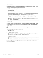
...does not reset the page count, the paper tray sizes, language, or formatter number. NOTE A cold reset also resets all network system parameters in NVRAM to perform a network reset. 1. Turn the printer on . 4. Turn off the printer. 2. After the network-reset process is complete, the device returns to the... cycling from front to hold the Job Cancel button for at step 1. Network reset A network reset changes all the HP Jetdirect settings as well as the printer settings. During this process, the Attention LED turns on , and continue to back. NOTE If the Attention and Ready...
...does not reset the page count, the paper tray sizes, language, or formatter number. NOTE A cold reset also resets all network system parameters in NVRAM to perform a network reset. 1. Turn the printer on . 4. Turn off the printer. 2. After the network-reset process is complete, the device returns to the... cycling from front to hold the Job Cancel button for at step 1. Network reset A network reset changes all the HP Jetdirect settings as well as the printer settings. During this process, the Attention LED turns on , and continue to back. NOTE If the Attention and Ready...

Service Manual
Page 290
...fan removing 103 fatal error secondary messages 147 FCC compliance 270 feeding problems, solving 152 formatter removing 97 fuser errors 149 part numbers 193, 229, 246 removing 103, 107 fuser...tab, HP ToolboxFX 30 high-voltage PCA 74 high-voltage power supply, checking 174 HP Customer Care Online 188 HP internal network port 5 HP media 8 HP Technical Training 188 HP ToolboxFX Device...1 4 tray 2 4 installing printer 18 interlock assembly, removing 118 internal components 71, 198 J jams detection operations 77 jams, clearing 160 L labels guidelines for using 9 laser/scanner errors 148 operations 70,...
...fan removing 103 fatal error secondary messages 147 FCC compliance 270 feeding problems, solving 152 formatter removing 97 fuser errors 149 part numbers 193, 229, 246 removing 103, 107 fuser...tab, HP ToolboxFX 30 high-voltage PCA 74 high-voltage power supply, checking 174 HP Customer Care Online 188 HP internal network port 5 HP media 8 HP Technical Training 188 HP ToolboxFX Device...1 4 tray 2 4 installing printer 18 interlock assembly, removing 118 internal components 71, 198 J jams detection operations 77 jams, clearing 160 L labels guidelines for using 9 laser/scanner errors 148 operations 70,...


