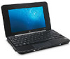
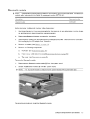
Mini 1100 Hard Drive Cable - HP PC
Mini 1100 Hard Drive Cable
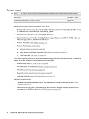
Related Manual Pages


Similar Questions


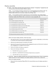
Hard Drive / Carry Case
My HP PAVILION HDX9000 is constantly giving me the message that I am running out of hard drive space...
My HP PAVILION HDX9000 is constantly giving me the message that I am running out of hard drive space...
(Posted by taylorn 11 years ago)
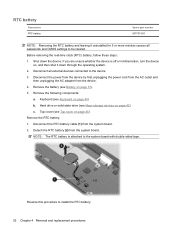
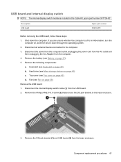
Remove Hard Drive
I'm replacing the keyboard in my dv7-3058dx and one of the screws for the keyboard I believe is unde...
I'm replacing the keyboard in my dv7-3058dx and one of the screws for the keyboard I believe is unde...
(Posted by twhitehouse 13 years ago)