HP PCL/PJL reference - Printer Job Language Technical Reference Addendum
Page 142
...or code meaning INSTALL CLEANING KIT INSTALL TRANFER KIT INSTALL FUSER KIT PERFORM PRINTER MAINTENANCE INSTALL SUPPLIES NON-HP Cartridge Installed T2 Roller missing Croller out Croller missing REMOVE SEALING TAPE E-label cartridge error ORDER BLACK TONER DAYS LEFT ORDER... CARTRIDGE DAYS LEFT ORDER YELLOW CARTRIDGE DAYS LEFT ORDER SUPPLIES DAYS LEFT REPLACE BLACK TONER REPLACE CYAN TONER REPLACE MAGENTA TONER REPLACE YELLOW TONER REPLACE BLACK CARTRIDGE REPLACE CYAN CARTRIDGE REPLACE MAGENTA CARTRIDGE REPLACE YELLOW CARTRIDGE REPLACE SUPPLIES 140 Chapter 4 PJL status codes ENWW Table 28.
...or code meaning INSTALL CLEANING KIT INSTALL TRANFER KIT INSTALL FUSER KIT PERFORM PRINTER MAINTENANCE INSTALL SUPPLIES NON-HP Cartridge Installed T2 Roller missing Croller out Croller missing REMOVE SEALING TAPE E-label cartridge error ORDER BLACK TONER DAYS LEFT ORDER... CARTRIDGE DAYS LEFT ORDER YELLOW CARTRIDGE DAYS LEFT ORDER SUPPLIES DAYS LEFT REPLACE BLACK TONER REPLACE CYAN TONER REPLACE MAGENTA TONER REPLACE YELLOW TONER REPLACE BLACK CARTRIDGE REPLACE CYAN CARTRIDGE REPLACE MAGENTA CARTRIDGE REPLACE YELLOW CARTRIDGE REPLACE SUPPLIES 140 Chapter 4 PJL status codes ENWW Table 28.
HP LaserJet 6L Printer - User Manual
Page 29
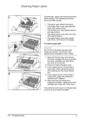
..., grasp the sheet and carefully pull it upward. 5 After removing all sheets and fragments of paper, replace the toner cartridge and close the Printer Door. Clearing Paper Jams Occasionally, paper can become jammed while printing.... • The Printer Door was opened while a job was printing. • The paper being used does not meet HP's specifications. • The paper being used was smaller than 76.2 x 127 mm (3 x 5 inches). The printer...clear a paper jam: Caution Do not touch the black sponge roller inside the printer and carefully pull the sheet toward you work on your printer.
..., grasp the sheet and carefully pull it upward. 5 After removing all sheets and fragments of paper, replace the toner cartridge and close the Printer Door. Clearing Paper Jams Occasionally, paper can become jammed while printing.... • The Printer Door was opened while a job was printing. • The paper being used does not meet HP's specifications. • The paper being used was smaller than 76.2 x 127 mm (3 x 5 inches). The printer...clear a paper jam: Caution Do not touch the black sponge roller inside the printer and carefully pull the sheet toward you work on your printer.
Service Manual
Page 6
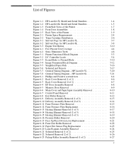
... Sensor Flag Replacement 6-23 Figure 6-20 Laser/Scanner Assembly Removal 6-24 Figure 6-21 Solenoid Removal (1 of 2 6-25 Figure 6-22 Solenoid Removal (2 of 2 6-26 Figure 6-23 Pickup Roller Assembly Removal (1 of the Printer 1-9 Figure 2-1 Printer Space Requirements 2-4 Figure 2-2 Toner Cartridge Distribution 2-6 Figure 3-1 Self-test Page for HP LaserJet 5L 3-7 Figure 3-2 Self-test Page for HP LaserJet 6L 3-8 Figure...
... Sensor Flag Replacement 6-23 Figure 6-20 Laser/Scanner Assembly Removal 6-24 Figure 6-21 Solenoid Removal (1 of 2 6-25 Figure 6-22 Solenoid Removal (2 of 2 6-26 Figure 6-23 Pickup Roller Assembly Removal (1 of the Printer 1-9 Figure 2-1 Printer Space Requirements 2-4 Figure 2-2 Toner Cartridge Distribution 2-6 Figure 3-1 Self-test Page for HP LaserJet 5L 3-7 Figure 3-2 Self-test Page for HP LaserJet 6L 3-8 Figure...
Service Manual
Page 7
... Feed Frame Removal (3 of 4 6-32 Figure 6-29 Paper Feed Frame Removal (4 of 4 6-33 Figure 6-30 Transfer Roller Guide & Transfer Roller Removal (Inside/Back View 6-34 Figure 6-31 Kick Plate Removal 6-35 Figure 6-32 Kick Plate Spring Replacement 6-36 Figure 6-33 Separation Pad Removal 6-37 Figure 6-34 Subpad Removal 6-38 Figure 6-35 Feed Assembly...
... Feed Frame Removal (3 of 4 6-32 Figure 6-29 Paper Feed Frame Removal (4 of 4 6-33 Figure 6-30 Transfer Roller Guide & Transfer Roller Removal (Inside/Back View 6-34 Figure 6-31 Kick Plate Removal 6-35 Figure 6-32 Kick Plate Spring Replacement 6-36 Figure 6-33 Separation Pad Removal 6-37 Figure 6-34 Subpad Removal 6-38 Figure 6-35 Feed Assembly...
Service Manual
Page 46
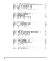
...Separation Pad & Sub pads RY7-5008-000CN RY7-5008-000CN 50,000 May affect paper movement. Look for glazing and/or cracks. Replace these components as needed, based on printer failures or wear, not strictly on Letter or A4 size paper with an average of 5%...50,000 Look for marks on pressure roller or upper Teflon sleeve. *The estimated toner cartridge life is based on usage. Table 4-1 Life Expectancy of Consumables Description HP LaserJet 5L HP LaserJet 6L Est Life Part Number Part Number (pgs) Remarks Toner Cartridge C3906A (user replaceable) C3906A 2,500* When print becomes...
...Separation Pad & Sub pads RY7-5008-000CN RY7-5008-000CN 50,000 May affect paper movement. Look for glazing and/or cracks. Replace these components as needed, based on printer failures or wear, not strictly on Letter or A4 size paper with an average of 5%...50,000 Look for marks on pressure roller or upper Teflon sleeve. *The estimated toner cartridge life is based on usage. Table 4-1 Life Expectancy of Consumables Description HP LaserJet 5L HP LaserJet 6L Est Life Part Number Part Number (pgs) Remarks Toner Cartridge C3906A (user replaceable) C3906A 2,500* When print becomes...
Service Manual
Page 64
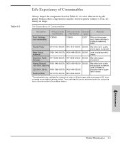
... of the drum and the drum is modified by the charging roller to paper. The beam sweeps the drum from any previous image. Step 1: Drum Cleaning The cleaning blade is in the replaceable toner cartridge, eliminates the need for a service call when replacement is applied by the print density setting. Functional Overview 5 - 13...
... of the drum and the drum is modified by the charging roller to paper. The beam sweeps the drum from any previous image. Step 1: Drum Cleaning The cleaning blade is in the replaceable toner cartridge, eliminates the need for a service call when replacement is applied by the print density setting. Functional Overview 5 - 13...
Service Manual
Page 74
...Replacement Contents Removal and Replacement Strategy 6-3 Required Tools 6-4 Installing Memory Cards (DRAM 6-5 Covers and Doors 6-6 Back Cover 6-6 EP Door Assembly 6-8 Memory Door 6-9 Main Cover and Paper Input Assembly 6-10 Internal Assemblies 6-11 Control Panel 6-11 Exit Roller Assembly 6-12 Delivery Assembly 6-13 Fuser Pressure Plate 6-15 Heating Element 6-17 Pressure Roller...Assemblies 6-24 Laser/Scanner Assembly 6-24 Solenoid 6-25 Pickup Roller Assembly 6-27 Paper Feed Frame 6-30 Transfer Roller Guide & Transfer Roller 6-34 Kick Plate 6-35 Separation Pad 6-37 Subpads ...
...Replacement Contents Removal and Replacement Strategy 6-3 Required Tools 6-4 Installing Memory Cards (DRAM 6-5 Covers and Doors 6-6 Back Cover 6-6 EP Door Assembly 6-8 Memory Door 6-9 Main Cover and Paper Input Assembly 6-10 Internal Assemblies 6-11 Control Panel 6-11 Exit Roller Assembly 6-12 Delivery Assembly 6-13 Fuser Pressure Plate 6-15 Heating Element 6-17 Pressure Roller...Assemblies 6-24 Laser/Scanner Assembly 6-24 Solenoid 6-25 Pickup Roller Assembly 6-27 Paper Feed Frame 6-30 Transfer Roller Guide & Transfer Roller 6-34 Kick Plate 6-35 Separation Pad 6-37 Subpads ...
Service Manual
Page 83
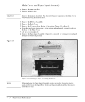
... 1 Remove the toner cartridge. 2 Remove memory door. Note Main Cover and Paper Input Assembly Removal When replacing the Paper Input Assembly, make certain that the mylar sheet is positioned between the Input Feed Roller and Separation Pad and that the sheet is not folded or bent. 6 - 10 Removal and... Replacement Remove the memory door first. The door will break if you remove the Main Cover without removing...
... 1 Remove the toner cartridge. 2 Remove memory door. Note Main Cover and Paper Input Assembly Removal When replacing the Paper Input Assembly, make certain that the mylar sheet is positioned between the Input Feed Roller and Separation Pad and that the sheet is not folded or bent. 6 - 10 Removal and... Replacement Remove the memory door first. The door will break if you remove the Main Cover without removing...

Service Manual
Page 85
... the gear end is possible to reinstall the Exit Roller so that has a gear attached must fit into the gear train. It is on the opposite side of the printer; this placement would cause paper path problems. 6 - 12 Removal and Replacement This will release the tabs from the printer chassis (...Figure 6-8, callout 1). 3 Rotate the tabs 90 degrees, clear of the Exit Roller bushings and pull inward.
... the gear end is possible to reinstall the Exit Roller so that has a gear attached must fit into the gear train. It is on the opposite side of the printer; this placement would cause paper path problems. 6 - 12 Removal and Replacement This will release the tabs from the printer chassis (...Figure 6-8, callout 1). 3 Rotate the tabs 90 degrees, clear of the Exit Roller bushings and pull inward.
Service Manual
Page 86
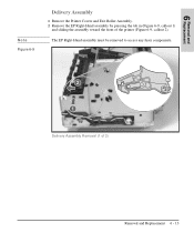
Delivery Assembly Removal (1 of the printer (Figure 6-9, callout 2). Removal and 6 Replacement Note Figure 6-9 Delivery Assembly 1 Remove the Printer Covers and Exit Roller Assembly. 2 Remove the EP Right-Hand assembly by pressing the tab in (Figure 6-9, callout 1) and sliding the assembly toward the front of 2) Removal and Replacement 6 - 13 The EP Right-Hand assembly must be removed to access any fuser components.
Delivery Assembly Removal (1 of the printer (Figure 6-9, callout 2). Removal and 6 Replacement Note Figure 6-9 Delivery Assembly 1 Remove the Printer Covers and Exit Roller Assembly. 2 Remove the EP Right-Hand assembly by pressing the tab in (Figure 6-9, callout 1) and sliding the assembly toward the front of 2) Removal and Replacement 6 - 13 The EP Right-Hand assembly must be removed to access any fuser components.
Service Manual
Page 93
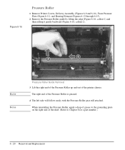
... of the Pressure Roller is greased. 4 The left side will follow easily with the Pressure Roller gear still attached. When reinstalling the Pressure Roller, apply a drop of grease to Chapter 8 for a part number.) 6 - 20 Removal and Replacement Figure 6-16 Pressure Roller 1 Remove Printer ...Covers, Delivery Assembly (Figures 6-9 and 6-10), Fuser Pressure Plate (Figure 6-11), and Heating Element (Figures 6-13 through 6-15). 2 Remove the Pressure Roller guide by lifting the edge (Figure 6-16, ...
... of the Pressure Roller is greased. 4 The left side will follow easily with the Pressure Roller gear still attached. When reinstalling the Pressure Roller, apply a drop of grease to Chapter 8 for a part number.) 6 - 20 Removal and Replacement Figure 6-16 Pressure Roller 1 Remove Printer ...Covers, Delivery Assembly (Figures 6-9 and 6-10), Fuser Pressure Plate (Figure 6-11), and Heating Element (Figures 6-13 through 6-15). 2 Remove the Pressure Roller guide by lifting the edge (Figure 6-16, ...

Service Manual
Page 94
... (Figures 6-13 through 6-15), and Pressure Roller (Figure 6-16). 2 Rotate the lever forward 90 degrees (past the spring) and pull it falls in place in front of the square tab (Figure 6-17). Figure 6-17 shows the lever from an HP LaserJet 5L. While the shape of the printer. To...will face you. 4 Release the spring so it straight out the front of the lever was changed for the HP LaserJet 6L (a stiffening rod was also added), these procedures for Face-Up/Face-Down Lever removal remain unchanged. Removal and Replacement 6 - 21 The machined ridges on the Separation Guide Assembly.
... (Figures 6-13 through 6-15), and Pressure Roller (Figure 6-16). 2 Rotate the lever forward 90 degrees (past the spring) and pull it falls in place in front of the square tab (Figure 6-17). Figure 6-17 shows the lever from an HP LaserJet 5L. While the shape of the printer. To...will face you. 4 Release the spring so it straight out the front of the lever was changed for the HP LaserJet 6L (a stiffening rod was also added), these procedures for Face-Up/Face-Down Lever removal remain unchanged. Removal and Replacement 6 - 21 The machined ridges on the Separation Guide Assembly.

Service Manual
Page 95
...Roller Removal 6 - 22 Removal and Replacement Note Figure 6-18 Fuser Exit Roller Assembly 1 Remove Printer Covers, Delivery Assembly (Figures 6-9 and 6-10), Fuser Pressure Plate (Figure 6-11), and Heating Element (Figures 6-13 through 6-15), Pressure Roller (Figure 6-16), and Face-Up/Face-Down Lever (Figure 6-17). 2 Remove the gear from an HP LaserJet 5L. 4 Slide the Exit Roller...end of the white tab was changed for the HP LaserJet 6L, these procedures for Fuser Exit Roller Assembly removal remain unchanged. While the shape of the roller shaft by pressing down on the catching mechanism ...
...Roller Removal 6 - 22 Removal and Replacement Note Figure 6-18 Fuser Exit Roller Assembly 1 Remove Printer Covers, Delivery Assembly (Figures 6-9 and 6-10), Fuser Pressure Plate (Figure 6-11), and Heating Element (Figures 6-13 through 6-15), Pressure Roller (Figure 6-16), and Face-Up/Face-Down Lever (Figure 6-17). 2 Remove the gear from an HP LaserJet 5L. 4 Slide the Exit Roller...end of the white tab was changed for the HP LaserJet 6L, these procedures for Fuser Exit Roller Assembly removal remain unchanged. While the shape of the roller shaft by pressing down on the catching mechanism ...
Service Manual
Page 100
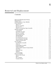
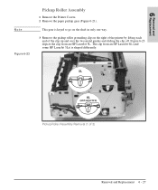
This gear is shaped differently. Removal and 6 Replacement Note Figure 6-23 Pickup Roller Assembly 1 Remove the Printer Covers. 2 Remove the paper pickup gear (Figure 6-21). Pickup Roller Assembly Removal (1 of the clip up and over the two metal guides and sliding the clip off. Figure 6-23 depicts the clip from an HP LaserJet 6L (and some HP LaserJet 5Ls) is keyed to go on the shaft in only one way. 3 Remove the pickup roller grounding clip on the right of the printer by lifting each end of 2) Removal and Replacement 6 - 27 The clip from an HP LaserJet 5L.
This gear is shaped differently. Removal and 6 Replacement Note Figure 6-23 Pickup Roller Assembly 1 Remove the Printer Covers. 2 Remove the paper pickup gear (Figure 6-21). Pickup Roller Assembly Removal (1 of the clip up and over the two metal guides and sliding the clip off. Figure 6-23 depicts the clip from an HP LaserJet 6L (and some HP LaserJet 5Ls) is keyed to go on the shaft in only one way. 3 Remove the pickup roller grounding clip on the right of the printer by lifting each end of 2) Removal and Replacement 6 - 27 The clip from an HP LaserJet 5L.

Service Manual
Page 101
Pickup Roller Assembly Removal (2 of 2) 5 Lift the bushing out. 6 From inside the front of the printer, slide the right side of the bushing out (Figure 6-24, callout 1), then turn it counter clockwise to release it (Figure 6-24, callout 2). Figure 6-24 4 Using needlenose pliers, pull the bottom of the Pickup Roller Assembly forward, then lift the left side out. 6 - 28 Removal and Replacement
Pickup Roller Assembly Removal (2 of 2) 5 Lift the bushing out. 6 From inside the front of the printer, slide the right side of the bushing out (Figure 6-24, callout 1), then turn it counter clockwise to release it (Figure 6-24, callout 2). Figure 6-24 4 Using needlenose pliers, pull the bottom of the Pickup Roller Assembly forward, then lift the left side out. 6 - 28 Removal and Replacement
Service Manual
Page 102
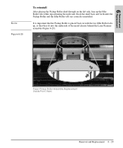
Paper Pickup Roller Assembly Replacement (Inside/Front View) Removal and Replacement 6 - 29 Rock the shaft back and forth until the Pickup Roller and the Idler Roller tabs are correctly reinstalled. It is important that the Pickup Roller is placed back in with the two Idler Roller tabs up the Idler Roller tabs while repositioning the right side. Removal and 6 Replacement Note Figure 6-25 To reinstall After placing the Pickup Roller shaft through on the left side, line up , so that they fit into the underside of the metal chassis behind the Laser/Scanner assembly (Figure 6-25).
Paper Pickup Roller Assembly Replacement (Inside/Front View) Removal and Replacement 6 - 29 Rock the shaft back and forth until the Pickup Roller and the Idler Roller tabs are correctly reinstalled. It is important that the Pickup Roller is placed back in with the two Idler Roller tabs up the Idler Roller tabs while repositioning the right side. Removal and 6 Replacement Note Figure 6-25 To reinstall After placing the Pickup Roller shaft through on the left side, line up , so that they fit into the underside of the metal chassis behind the Laser/Scanner assembly (Figure 6-25).
Service Manual
Page 103
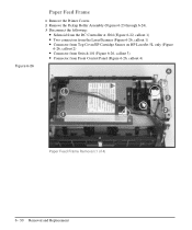
Figure 6-26 Paper Feed Frame 1 Remove the Printer Covers. 2 Remove the Pickup Roller Assembly (Figures 6-23 through 6-24). 3 Disconnect the following: • Solenoid from the DC Controller at J204 (Figure 6-22, callout 1) • Two connectors from the Laser/Scanner (Figure 6-26, callout 1) • Connector from Top Cover/EP Cartridge Sensor on HP LaserJet 5L only (Figure 6-26, callout 2) • Connector from Switch 101 (Figure 6-26, callout 3) • Connector from Front Control Panel (Figure 6-26, callout 4) Paper Feed Frame Removal (1 of 4) 6 - 30 Removal and Replacement
Figure 6-26 Paper Feed Frame 1 Remove the Printer Covers. 2 Remove the Pickup Roller Assembly (Figures 6-23 through 6-24). 3 Disconnect the following: • Solenoid from the DC Controller at J204 (Figure 6-22, callout 1) • Two connectors from the Laser/Scanner (Figure 6-26, callout 1) • Connector from Top Cover/EP Cartridge Sensor on HP LaserJet 5L only (Figure 6-26, callout 2) • Connector from Switch 101 (Figure 6-26, callout 3) • Connector from Front Control Panel (Figure 6-26, callout 4) Paper Feed Frame Removal (1 of 4) 6 - 30 Removal and Replacement
Service Manual
Page 107
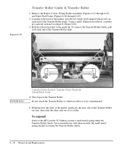
To reinstall Some of the HP LaserJet 5L Printers contain a small metal spring under the Transfer Roller Guide. 6 - 34 Removal and Replacement Do not touch the Transfer Roller or otherwise allow it to release it off each end of its socket. WARNING! Upon reinstallation with these models, the small metal spring should rest ...
To reinstall Some of the HP LaserJet 5L Printers contain a small metal spring under the Transfer Roller Guide. 6 - 34 Removal and Replacement Do not touch the Transfer Roller or otherwise allow it to release it off each end of its socket. WARNING! Upon reinstallation with these models, the small metal spring should rest ...
Service Manual
Page 108
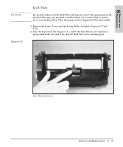
... to pivot upward (a spring underneath will push it is also likely to the Kick Plate, but it up). Kick Plate Removal Removal and Replacement 6 - 35 Lift the Kick Plate off its mounting pins. The spring underneath the Kick Plate may stay attached to spring away from the... Kick Plate. Place the spring aside for Separation Plate disassembly. 1 Remove the Printer Covers and the Pickup Roller Assembly (Figures 6-23 and 6-24). 2 Press the Separation Pad (Figure 6-31). Removal and 6 Replacement Caution Figure 6-31 Kick Plate Be careful working with the Kick Plate and Separation Pad.
... to pivot upward (a spring underneath will push it is also likely to the Kick Plate, but it up). Kick Plate Removal Removal and Replacement 6 - 35 Lift the Kick Plate off its mounting pins. The spring underneath the Kick Plate may stay attached to spring away from the... Kick Plate. Place the spring aside for Separation Plate disassembly. 1 Remove the Printer Covers and the Pickup Roller Assembly (Figures 6-23 and 6-24). 2 Press the Separation Pad (Figure 6-31). Removal and 6 Replacement Caution Figure 6-31 Kick Plate Be careful working with the Kick Plate and Separation Pad.

Service Manual
Page 110
This will release the Separation Pad (Figure 6-33). 3 Lift the Separation Pad 90 degrees and slide its mounting pins out of the Paper Feed Frame. Separation Pad Removal Removal and Replacement 6 - 37 Removal and 6 Replacement Figure 6-33 Separation Pad 1 Remove the Printer Covers, Pickup Roller Assembly (Figures 6-23 and 6-24), and Kick Plate (Figure 6-31). 2 Lift the bottom of the white plastic tab on the rear of the Paper Feed Frame up slightly and slide it up, toward the top of their retainers.
This will release the Separation Pad (Figure 6-33). 3 Lift the Separation Pad 90 degrees and slide its mounting pins out of the Paper Feed Frame. Separation Pad Removal Removal and Replacement 6 - 37 Removal and 6 Replacement Figure 6-33 Separation Pad 1 Remove the Printer Covers, Pickup Roller Assembly (Figures 6-23 and 6-24), and Kick Plate (Figure 6-31). 2 Lift the bottom of the white plastic tab on the rear of the Paper Feed Frame up slightly and slide it up, toward the top of their retainers.


