Service Manual
Page 6
... Solenoid Removal (1 of 2 6-25 Figure 6-22 Solenoid Removal (2 of 2 6-26 Figure 6-23 Pickup Roller Assembly Removal (1 of the Printer 1-9 Figure 2-1 Printer Space Requirements 2-4 Figure 2-2 Toner Cartridge Distribution 2-6 Figure 3-1 Self-test Page for HP LaserJet 5L 3-7 Figure 3-2 Self-test Page for HP LaserJet 6L 3-8 Figure 3-3 Engine Test Button 3-10 Figure 4-1 Five Percent Text Coverage 4-4 Figure 4-2 Static Eliminator Teeth...
... Solenoid Removal (1 of 2 6-25 Figure 6-22 Solenoid Removal (2 of 2 6-26 Figure 6-23 Pickup Roller Assembly Removal (1 of the Printer 1-9 Figure 2-1 Printer Space Requirements 2-4 Figure 2-2 Toner Cartridge Distribution 2-6 Figure 3-1 Self-test Page for HP LaserJet 5L 3-7 Figure 3-2 Self-test Page for HP LaserJet 6L 3-8 Figure 3-3 Engine Test Button 3-10 Figure 4-1 Five Percent Text Coverage 4-4 Figure 4-2 Static Eliminator Teeth...
Service Manual
Page 7
... Defect Ruler 7-29 Figure 8-1 Major Assembly Locations 8-7 Figure 8-2 Covers and Doors 8-8 Figure 8-3 Internal Components (1 of 3 8-10 Figure 8-4 Internal Components (2 of 3 8-12 Figure 8-5 Internal Components (3 of 3 8-14 Figure 8-6 DC Controller/Formatter and Cables 8-16 Figure 8-7 Pickup Roller Assembly 8-18 Figure 8-8 Feed Assembly 8-20 Figure 8-9 Separation Guide Assembly 8-22 Figure 8-10 Delivery Assembly 8-24 Figure B-1 VCCI Statement (Japan...
... Defect Ruler 7-29 Figure 8-1 Major Assembly Locations 8-7 Figure 8-2 Covers and Doors 8-8 Figure 8-3 Internal Components (1 of 3 8-10 Figure 8-4 Internal Components (2 of 3 8-12 Figure 8-5 Internal Components (3 of 3 8-14 Figure 8-6 DC Controller/Formatter and Cables 8-16 Figure 8-7 Pickup Roller Assembly 8-18 Figure 8-8 Feed Assembly 8-20 Figure 8-9 Separation Guide Assembly 8-22 Figure 8-10 Delivery Assembly 8-24 Figure B-1 VCCI Statement (Japan...
Service Manual
Page 74
... 6-9 Main Cover and Paper Input Assembly 6-10 Internal Assemblies 6-11 Control Panel 6-11 Exit Roller Assembly 6-12 Delivery Assembly 6-13 Fuser Pressure Plate 6-15 Heating Element 6-17 Pressure Roller 6-20 Face-Up/Face-Down Lever 6-21 Fuser Exit Roller Assembly 6-22 Paper Exit Sensor Flag 6-23 Top Assemblies 6-24 Laser/Scanner Assembly 6-24 Solenoid 6-25 Pickup Roller Assembly 6-27 Paper Feed Frame...
... 6-9 Main Cover and Paper Input Assembly 6-10 Internal Assemblies 6-11 Control Panel 6-11 Exit Roller Assembly 6-12 Delivery Assembly 6-13 Fuser Pressure Plate 6-15 Heating Element 6-17 Pressure Roller 6-20 Face-Up/Face-Down Lever 6-21 Fuser Exit Roller Assembly 6-22 Paper Exit Sensor Flag 6-23 Top Assemblies 6-24 Laser/Scanner Assembly 6-24 Solenoid 6-25 Pickup Roller Assembly 6-27 Paper Feed Frame...

Service Manual
Page 85
...Figure 6-8, callout 1). 3 Rotate the tabs 90 degrees, clear of the Exit Roller bushings and pull inward. this placement would cause paper path problems. 6 - 12 Removal and Replacement It is possible to reinstall the Exit Roller so that has a gear attached must fit into the gear train. Exit... Roller Removal To reinstall The end of the Exit Roller that the gear end is on the opposite side of the printer; Figure 6-8 Exit Roller Assembly 1 Remove Printer Covers. 2 Grasp both tabs at the lower ends of the printer chassis ...
...Figure 6-8, callout 1). 3 Rotate the tabs 90 degrees, clear of the Exit Roller bushings and pull inward. this placement would cause paper path problems. 6 - 12 Removal and Replacement It is possible to reinstall the Exit Roller so that has a gear attached must fit into the gear train. Exit... Roller Removal To reinstall The end of the Exit Roller that the gear end is on the opposite side of the printer; Figure 6-8 Exit Roller Assembly 1 Remove Printer Covers. 2 Grasp both tabs at the lower ends of the printer chassis ...
Service Manual
Page 86
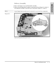
Delivery Assembly Removal (1 of the printer (Figure 6-9, callout 2). The EP Right-Hand assembly must be removed to access any fuser components. Removal and 6 Replacement Note Figure 6-9 Delivery Assembly 1 Remove the Printer Covers and Exit Roller Assembly. 2 Remove the EP Right-Hand assembly by pressing the tab in (Figure 6-9, callout 1) and sliding the assembly toward the front of 2) Removal and Replacement 6 - 13
Delivery Assembly Removal (1 of the printer (Figure 6-9, callout 2). The EP Right-Hand assembly must be removed to access any fuser components. Removal and 6 Replacement Note Figure 6-9 Delivery Assembly 1 Remove the Printer Covers and Exit Roller Assembly. 2 Remove the EP Right-Hand assembly by pressing the tab in (Figure 6-9, callout 1) and sliding the assembly toward the front of 2) Removal and Replacement 6 - 13

Service Manual
Page 95
...Face-Up/Face-Down Lever (Figure 6-17). 2 Remove the gear from an HP LaserJet 5L. 4 Slide the Exit Roller Assembly forward and out to the right of the printer. While the shape of the roller shaft by pressing down on the catching mechanism with the small flathead screwdriver and... the Exit Roller Assembly by pressing the small, white tab upward (Figure 6-18, callout 1) and rotating it around (Figure 6-18, callout 2). Figure 6-18 shows the white tab from the left end of the white tab was changed for the HP LaserJet 6L, these procedures for Fuser Exit Roller Assembly removal remain unchanged...
...Face-Up/Face-Down Lever (Figure 6-17). 2 Remove the gear from an HP LaserJet 5L. 4 Slide the Exit Roller Assembly forward and out to the right of the printer. While the shape of the roller shaft by pressing down on the catching mechanism with the small flathead screwdriver and... the Exit Roller Assembly by pressing the small, white tab upward (Figure 6-18, callout 1) and rotating it around (Figure 6-18, callout 2). Figure 6-18 shows the white tab from the left end of the white tab was changed for the HP LaserJet 6L, these procedures for Fuser Exit Roller Assembly removal remain unchanged...
Service Manual
Page 100
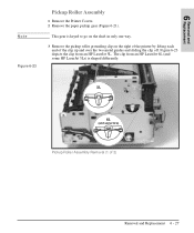
Figure 6-23 depicts the clip from an HP LaserJet 6L (and some HP LaserJet 5Ls) is keyed to go on the shaft in only one way. 3 Remove the pickup roller grounding clip on the right of the printer by lifting each end of 2) Removal and Replacement 6 - 27 This gear is shaped differently. The clip from an HP LaserJet 5L. Removal and 6 Replacement Note Figure 6-23 Pickup Roller Assembly 1 Remove the Printer Covers. 2 Remove the paper pickup gear (Figure 6-21). Pickup Roller Assembly Removal (1 of the clip up and over the two metal guides and sliding the clip off.
Figure 6-23 depicts the clip from an HP LaserJet 6L (and some HP LaserJet 5Ls) is keyed to go on the shaft in only one way. 3 Remove the pickup roller grounding clip on the right of the printer by lifting each end of 2) Removal and Replacement 6 - 27 This gear is shaped differently. The clip from an HP LaserJet 5L. Removal and 6 Replacement Note Figure 6-23 Pickup Roller Assembly 1 Remove the Printer Covers. 2 Remove the paper pickup gear (Figure 6-21). Pickup Roller Assembly Removal (1 of the clip up and over the two metal guides and sliding the clip off.

Service Manual
Page 101
Figure 6-24 4 Using needlenose pliers, pull the bottom of the Pickup Roller Assembly forward, then lift the left side out. 6 - 28 Removal and Replacement Pickup Roller Assembly Removal (2 of 2) 5 Lift the bushing out. 6 From inside the front of the printer, slide the right side of the bushing out (Figure 6-24, callout 1), then turn it counter clockwise to release it (Figure 6-24, callout 2).
Figure 6-24 4 Using needlenose pliers, pull the bottom of the Pickup Roller Assembly forward, then lift the left side out. 6 - 28 Removal and Replacement Pickup Roller Assembly Removal (2 of 2) 5 Lift the bushing out. 6 From inside the front of the printer, slide the right side of the bushing out (Figure 6-24, callout 1), then turn it counter clockwise to release it (Figure 6-24, callout 2).
Service Manual
Page 102
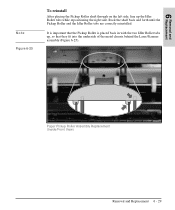
Rock the shaft back and forth until the Pickup Roller and the Idler Roller tabs are correctly reinstalled. It is placed back in with the two Idler Roller tabs up the Idler Roller tabs while repositioning the right side. Paper Pickup Roller Assembly Replacement (Inside/Front View) Removal and Replacement 6 - 29 Removal and 6 Replacement Note Figure 6-25 To reinstall After placing the Pickup Roller shaft through on the left side, line up , so that the Pickup Roller is important that they fit into the underside of the metal chassis behind the Laser/Scanner assembly (Figure 6-25).
Rock the shaft back and forth until the Pickup Roller and the Idler Roller tabs are correctly reinstalled. It is placed back in with the two Idler Roller tabs up the Idler Roller tabs while repositioning the right side. Paper Pickup Roller Assembly Replacement (Inside/Front View) Removal and Replacement 6 - 29 Removal and 6 Replacement Note Figure 6-25 To reinstall After placing the Pickup Roller shaft through on the left side, line up , so that the Pickup Roller is important that they fit into the underside of the metal chassis behind the Laser/Scanner assembly (Figure 6-25).
Service Manual
Page 103
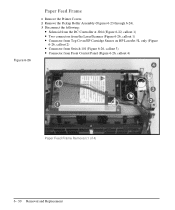
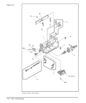
Figure 6-26 Paper Feed Frame 1 Remove the Printer Covers. 2 Remove the Pickup Roller Assembly (Figures 6-23 through 6-24). 3 Disconnect the following: • Solenoid from the DC Controller at J204 (Figure 6-22, callout 1) • Two connectors from the Laser/Scanner (Figure 6-26, callout 1) • Connector from Top Cover/EP Cartridge Sensor on HP LaserJet 5L only (Figure 6-26, callout 2) • Connector from Switch 101 (Figure 6-26, callout 3) • Connector from Front Control Panel (Figure 6-26, callout 4) Paper Feed Frame Removal (1 of 4) 6 - 30 Removal and Replacement
Figure 6-26 Paper Feed Frame 1 Remove the Printer Covers. 2 Remove the Pickup Roller Assembly (Figures 6-23 through 6-24). 3 Disconnect the following: • Solenoid from the DC Controller at J204 (Figure 6-22, callout 1) • Two connectors from the Laser/Scanner (Figure 6-26, callout 1) • Connector from Top Cover/EP Cartridge Sensor on HP LaserJet 5L only (Figure 6-26, callout 2) • Connector from Switch 101 (Figure 6-26, callout 3) • Connector from Front Control Panel (Figure 6-26, callout 4) Paper Feed Frame Removal (1 of 4) 6 - 30 Removal and Replacement
Service Manual
Page 107
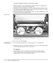
... end of the Transfer Roller guide. To reinstall Some of the HP LaserJet 5L Printers contain a small metal spring under the Transfer Roller Guide. 6 - 34 Removal and Replacement WARNING! Transfer Roller Guide & Transfer Roller Removal (Inside/Back View) 4 This exposes the Transfer Roller. Figure 6-30 Transfer Roller Guide & Transfer Roller 1 Remove the Printer Covers, Pickup Roller Assembly (Figures 6-23 through 6-25...
... end of the Transfer Roller guide. To reinstall Some of the HP LaserJet 5L Printers contain a small metal spring under the Transfer Roller Guide. 6 - 34 Removal and Replacement WARNING! Transfer Roller Guide & Transfer Roller Removal (Inside/Back View) 4 This exposes the Transfer Roller. Figure 6-30 Transfer Roller Guide & Transfer Roller 1 Remove the Printer Covers, Pickup Roller Assembly (Figures 6-23 through 6-25...
Service Manual
Page 108
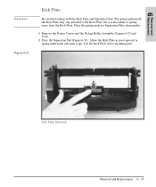
... Kick Plate. Lift the Kick Plate off its mounting pins. Place the spring aside for Separation Plate disassembly. 1 Remove the Printer Covers and the Pickup Roller Assembly (Figures 6-23 and 6-24). 2 Press the Separation Pad (Figure 6-31). The spring underneath the Kick Plate may stay attached to the Kick Plate, but it...
... Kick Plate. Lift the Kick Plate off its mounting pins. Place the spring aside for Separation Plate disassembly. 1 Remove the Printer Covers and the Pickup Roller Assembly (Figures 6-23 and 6-24). 2 Press the Separation Pad (Figure 6-31). The spring underneath the Kick Plate may stay attached to the Kick Plate, but it...

Service Manual
Page 110
Removal and 6 Replacement Figure 6-33 Separation Pad 1 Remove the Printer Covers, Pickup Roller Assembly (Figures 6-23 and 6-24), and Kick Plate (Figure 6-31). 2 Lift the bottom of the white plastic tab on the rear of the Paper Feed Frame up slightly and slide it up, toward the top of their retainers. This will release the Separation Pad (Figure 6-33). 3 Lift the Separation Pad 90 degrees and slide its mounting pins out of the Paper Feed Frame. Separation Pad Removal Removal and Replacement 6 - 37
Removal and 6 Replacement Figure 6-33 Separation Pad 1 Remove the Printer Covers, Pickup Roller Assembly (Figures 6-23 and 6-24), and Kick Plate (Figure 6-31). 2 Lift the bottom of the white plastic tab on the rear of the Paper Feed Frame up slightly and slide it up, toward the top of their retainers. This will release the Separation Pad (Figure 6-33). 3 Lift the Separation Pad 90 degrees and slide its mounting pins out of the Paper Feed Frame. Separation Pad Removal Removal and Replacement 6 - 37

Service Manual
Page 112
Removal and 6 Replacement Figure 6-35 Feed Assembly The Feed Assembly is located in the Paper Feed Frame. 1 Remove the Printer Covers, Pickup Roller Assembly (Figures 6-23 through 6-25), and Paper Feed Frame (Figures 6-26 through 6-29). 2 Turn the Paper Feed Frame upside down. 3 Remove the Feed Roller Shaft by lifting the plastic tab up (Figure 6-35, callout 1) and sliding it out the side of 3) Removal and Replacement 6 - 39 Feed Assembly Removal (1 of the Paper Feed Frame (Figure 6-35, callout 2).
Removal and 6 Replacement Figure 6-35 Feed Assembly The Feed Assembly is located in the Paper Feed Frame. 1 Remove the Printer Covers, Pickup Roller Assembly (Figures 6-23 through 6-25), and Paper Feed Frame (Figures 6-26 through 6-29). 2 Turn the Paper Feed Frame upside down. 3 Remove the Feed Roller Shaft by lifting the plastic tab up (Figure 6-35, callout 1) and sliding it out the side of 3) Removal and Replacement 6 - 39 Feed Assembly Removal (1 of the Paper Feed Frame (Figure 6-35, callout 2).
Service Manual
Page 171
Figure 8-7 Pickup Roller Assembly 8-18 Parts and Diagrams
Figure 8-7 Pickup Roller Assembly 8-18 Parts and Diagrams

Service Manual
Page 172
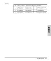
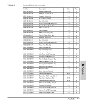
Table 8-8 Ref LaserJet 5L Part No. Qty Description 1 RB1-7177-000CN RB1-7177-000CN 1 Paper Feed Frame 2 RY7-5008-000CN RY7-5008-000CN 1 Separation Pad Assembly 3 RY7-5009-000CN RY7-5009-000CN 1 Input Sensor Assembly 4 RG5-1951-000CN RG5-3486-000CN 1 Pickup Roller Assembly 5 RB1-7184-000CN RB1-7184-000CN 1 Pickup Roller Bushing 6 RB1-7197-000CN RB1...-000CN RF5-2372-000CN 1 Paper Kick Plate 501 XB4-7401-0007 XB4-7401-0007 2 Screw, TP, PH, M4x10 Parts and 8 Diagrams Parts and Diagrams 8-19 LaserJet 6L Part No.
Table 8-8 Ref LaserJet 5L Part No. Qty Description 1 RB1-7177-000CN RB1-7177-000CN 1 Paper Feed Frame 2 RY7-5008-000CN RY7-5008-000CN 1 Separation Pad Assembly 3 RY7-5009-000CN RY7-5009-000CN 1 Input Sensor Assembly 4 RG5-1951-000CN RG5-3486-000CN 1 Pickup Roller Assembly 5 RB1-7184-000CN RB1-7184-000CN 1 Pickup Roller Bushing 6 RB1-7197-000CN RB1...-000CN RF5-2372-000CN 1 Paper Kick Plate 501 XB4-7401-0007 XB4-7401-0007 2 Screw, TP, PH, M4x10 Parts and 8 Diagrams Parts and Diagrams 8-19 LaserJet 6L Part No.
Service Manual
Page 176
Qty Description RG5-2013-000CN RG5-3475-000CN 1 Separation Guide Assembly 2 RB1-7276-000CN RG5-3476-000CN 1 Face-Up/Face-Down Lever 4 RB1-7289-000CN RB2-1690-000CN 1 Fuser Roller Bushing 7 RF5-1522-000CN RF5-2368-000CN 1 Fuser Exit Roller Assembly Parts and 8 Diagrams Parts and Diagrams 8-23 Table 8-10 Ref LaserJet 5L Part No. LaserJet 6L Part No.
Qty Description RG5-2013-000CN RG5-3475-000CN 1 Separation Guide Assembly 2 RB1-7276-000CN RG5-3476-000CN 1 Face-Up/Face-Down Lever 4 RB1-7289-000CN RB2-1690-000CN 1 Fuser Roller Bushing 7 RF5-1522-000CN RF5-2368-000CN 1 Fuser Exit Roller Assembly Parts and 8 Diagrams Parts and Diagrams 8-23 Table 8-10 Ref LaserJet 5L Part No. LaserJet 6L Part No.

Service Manual
Page 182
... (5L) EP/Cover Interlock (6L) Exit Roller (5L) Exit Roller (6L) Exit Roller Bushing Face-up/Face-down Shaft (5L) Face-up/Face-down Shaft (6L) Face-up/Face-down Switch (5L) Face-up/Face-down Switch (6L) Feed Assembly (5L) Feed Assembly (6L) Flag Flag Spring Formatter Shield (5L) Formatter Shield (6L) Formatter (Exchange) (5L) Formatter... Case Fuse 101 (110 V) Fuse 101 (220 V) Fuse 102 (110 V) Fuser Cable Guide Fuser Connector Fuser Exit Roller Assembly (5L) Fuser Exit Roller Assembly (6L) Fuser Paper Guide Part No. RG5-2037-000CN RF5-1501-030CN RF5-2352-000CN RB1-7327-000CN RB2-1697-000CN RF5...
... (5L) EP/Cover Interlock (6L) Exit Roller (5L) Exit Roller (6L) Exit Roller Bushing Face-up/Face-down Shaft (5L) Face-up/Face-down Shaft (6L) Face-up/Face-down Switch (5L) Face-up/Face-down Switch (6L) Feed Assembly (5L) Feed Assembly (6L) Flag Flag Spring Formatter Shield (5L) Formatter Shield (6L) Formatter (Exchange) (5L) Formatter... Case Fuse 101 (110 V) Fuse 101 (220 V) Fuse 102 (110 V) Fuser Cable Guide Fuser Connector Fuser Exit Roller Assembly (5L) Fuser Exit Roller Assembly (6L) Fuser Paper Guide Part No. RG5-2037-000CN RF5-1501-030CN RF5-2352-000CN RB1-7327-000CN RB2-1697-000CN RF5...

Service Manual
Page 184
... Frame Paper Kick Plate (5L) Paper Kick Plate (6L) Paper Pickup Roller Cable Pickup Roller Assembly (5L) Pickup Roller Assembly (6L) Pickup Roller Bushing Pickup Roller Grounding Clip Pressure Roller (5L) Pressure Roller (6L) Pressure Roller Bushing Pressure Roller Gear Pressure Roller Grease Pressure Roller Grounding Guide Right Leg Right Pressure Roller Housing Scanner Cable (5L) Scanner Cable (6L) Part No. RB1-7255-000CN RG5-1995-000CN RG5...
... Frame Paper Kick Plate (5L) Paper Kick Plate (6L) Paper Pickup Roller Cable Pickup Roller Assembly (5L) Pickup Roller Assembly (6L) Pickup Roller Bushing Pickup Roller Grounding Clip Pressure Roller (5L) Pressure Roller (6L) Pressure Roller Bushing Pressure Roller Gear Pressure Roller Grease Pressure Roller Grounding Guide Right Leg Right Pressure Roller Housing Scanner Cable (5L) Scanner Cable (6L) Part No. RB1-7255-000CN RG5-1995-000CN RG5...
Service Manual
Page 188
... Guide EP Right Hand Guide #1 Pressure Roller (5L) Fuser Pressure Plate Exit Roller (5L) Fuser Exit Roller Assembly (5L) Transfer Roller Guide (5L) PR Ground Guide Transfer Roller EP Door Assembly (6L) Transfer Roller Guide (6L) Pressure Roller (6L) Exit Roller (6L) Fuser Exit Roller Assembly (6L) Paper Kick Plate (6L) Feed Assembly (5L) Input Assembly 1 (5L) Input Assembly 2 (5L) Idler Roller Shaft Assembly Pickup Roller Assembly (5L) Transfer Guide Assembly (5L) Heating Element (110 V) (5L...
... Guide EP Right Hand Guide #1 Pressure Roller (5L) Fuser Pressure Plate Exit Roller (5L) Fuser Exit Roller Assembly (5L) Transfer Roller Guide (5L) PR Ground Guide Transfer Roller EP Door Assembly (6L) Transfer Roller Guide (6L) Pressure Roller (6L) Exit Roller (6L) Fuser Exit Roller Assembly (6L) Paper Kick Plate (6L) Feed Assembly (5L) Input Assembly 1 (5L) Input Assembly 2 (5L) Idler Roller Shaft Assembly Pickup Roller Assembly (5L) Transfer Guide Assembly (5L) Heating Element (110 V) (5L...


