
Service Guide
Page 6
... guidelines 47 Equipment guidelines 48 Unknown user password 49 Component replacement procedures 50 Service tag ...50 Computer feet ...51 Battery ...52 Webcam/microphone module 53 Optical drive ...55 TV tuner module ...57 RTC battery ...59 Memory module ...60 Hard drive ...62 WLAN module ...65 Switch cover and keyboard 69 Power button board...
... guidelines 47 Equipment guidelines 48 Unknown user password 49 Component replacement procedures 50 Service tag ...50 Computer feet ...51 Battery ...52 Webcam/microphone module 53 Optical drive ...55 TV tuner module ...57 RTC battery ...59 Memory module ...60 Hard drive ...62 WLAN module ...65 Switch cover and keyboard 69 Power button board...

Service Guide
Page 8
Recovering from the dedicated recovery partition (select models only 146 9 Connector pin assignments 1394 ...147 Audio-in (microphone) ...147 Audio-out (headphone) ...148 External monitor ...148 HDMI ...149 RJ-11 (modem) ...150 RJ-45 (network) ...150 Universal Serial Bus ...151 10 Power cord set requirements Requirements for all countries or regions 152 Requirements for specific countries or regions 153 11 Recycling Battery ...154 Display ...154 Index ...160 viii
Recovering from the dedicated recovery partition (select models only 146 9 Connector pin assignments 1394 ...147 Audio-in (microphone) ...147 Audio-out (headphone) ...148 External monitor ...148 HDMI ...149 RJ-11 (modem) ...150 RJ-45 (network) ...150 Universal Serial Bus ...151 10 Power cord set requirements Requirements for all countries or regions 152 Requirements for specific countries or regions 153 11 Recycling Battery ...154 Display ...154 Index ...160 viii
Service Guide
Page 14
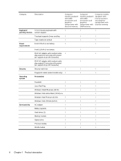
... √ Taps enabled as default √ √ √ Power 8-cell 2.55-Ah Li-ion battery √ √ requirements 6-cell 2.20-Ah Li-ion battery √ 90-W AC adapter with localized cable √ √ plug support (2-wire plug with ground pin...Vista Premium (32 bit) √ √ √ Windows Vista Ultimate (64 bit) √ √ √ Serviceability AC adapter √ √ √ Battery (system) √ √ √ Hard drives (2) √ √ √ Memory module √ √ √ Optical drive √ √ ...
... √ Taps enabled as default √ √ √ Power 8-cell 2.55-Ah Li-ion battery √ √ requirements 6-cell 2.20-Ah Li-ion battery √ 90-W AC adapter with localized cable √ √ plug support (2-wire plug with ground pin...Vista Premium (32 bit) √ √ √ Windows Vista Ultimate (64 bit) √ √ √ Serviceability AC adapter √ √ √ Battery (system) √ √ √ Hard drives (2) √ √ √ Memory module √ √ √ Optical drive √ √ ...
Service Guide
Page 21
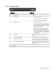
... external power source, the light stays off until the battery reaches a low battery level. (3) Drive light Blinking: The hard drive or optical drive is being accessed. (4) Consumer infrared lens Receives a signal from the HP Remote Control. (5) Audio-in Help and Support. Front... components 13 Front components Item Component Function (1) Power light ● On: The computer is on. (2) Battery light ● Blinking: The computer is in the Sleep ...
... external power source, the light stays off until the battery reaches a low battery level. (3) Drive light Blinking: The hard drive or optical drive is being accessed. (4) Consumer infrared lens Receives a signal from the HP Remote Control. (5) Audio-in Help and Support. Front... components 13 Front components Item Component Function (1) Power light ● On: The computer is on. (2) Battery light ● Blinking: The computer is in the Sleep ...
Service Guide
Page 24
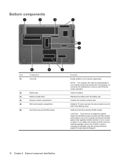
Bottom components Item (1) Component Vents (8) (2) Battery bay (3) Battery release latch (4) Memory module compartment (5) Mini Card module compartment (6) Hard drive bay and WLAN module Function Enable airflow to cool internal components and prevent ... identification If you replace the module and then receive a warning message, remove the module to cycle on and off during routine operation. Releases the battery from the battery bay. Holds the hard drive and the WLAN module. CAUTION: To prevent an unresponsive system, replace the wireless module only with a wireless module...
Bottom components Item (1) Component Vents (8) (2) Battery bay (3) Battery release latch (4) Memory module compartment (5) Mini Card module compartment (6) Hard drive bay and WLAN module Function Enable airflow to cool internal components and prevent ... identification If you replace the module and then receive a warning message, remove the module to cycle on and off during routine operation. Releases the battery from the battery bay. Holds the hard drive and the WLAN module. CAUTION: To prevent an unresponsive system, replace the wireless module only with a wireless module...
Service Guide
Page 30
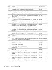
... computer models equipped with Intel processors 484268-001 1024-MB memory module for use only with computer models equipped with silver bezel 483863-001 RTC battery 491571-001 TV tuner modules: NOTE: The TV tuner module spare part kits do not include a TV tuner module cable. Item (18) (19) (20) (21... use only with computer models equipped with 484170-002 AMD processors 6-cell, 47-Wh, 2.55-Ah Li-ion battery for use only with computer models equipped with 484170-001 Intel processors Optical drives (include bezel and bracket): Blu-ray Disc ROM Drive with SuperMulti ...
... computer models equipped with Intel processors 484268-001 1024-MB memory module for use only with computer models equipped with silver bezel 483863-001 RTC battery 491571-001 TV tuner modules: NOTE: The TV tuner module spare part kits do not include a TV tuner module cable. Item (18) (19) (20) (21... use only with computer models equipped with 484170-002 AMD processors 6-cell, 47-Wh, 2.55-Ah Li-ion battery for use only with computer models equipped with 484170-001 Intel processors Optical drives (include bezel and bracket): Blu-ray Disc ROM Drive with SuperMulti ...
Service Guide
Page 47
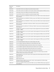
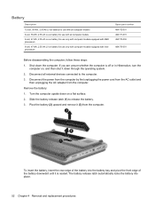
... 485339-001 485340-001 485343-001 485344-001 485345-001 486523-001 Description 6-cell, 55-Wh, 2.55-Ah Li-ion battery for use with all computer models 6-cell, 47-Wh, 2.55-Ah Li-ion battery for use only with computer models equipped with AMD processors 6-cell, 55-Wh, 2.55-Ah Li-ion... Screw Kit Display Hinge Screw Kit Webcam/microphone module for use only with computer models equipped with AntiGlare display assemblies (includes double-sided tape) Intel Core Duo T8400 2.26-GHz processor with 3-MB L2 cache and 1066-MHz FSB (includes replacement thermal material) Sequential part number listing 39
... 485339-001 485340-001 485343-001 485344-001 485345-001 486523-001 Description 6-cell, 55-Wh, 2.55-Ah Li-ion battery for use with all computer models 6-cell, 47-Wh, 2.55-Ah Li-ion battery for use only with computer models equipped with AMD processors 6-cell, 55-Wh, 2.55-Ah Li-ion... Screw Kit Display Hinge Screw Kit Webcam/microphone module for use only with computer models equipped with AntiGlare display assemblies (includes double-sided tape) Intel Core Duo T8400 2.26-GHz processor with 3-MB L2 cache and 1066-MHz FSB (includes replacement thermal material) Sequential part number listing 39
Service Guide
Page 51
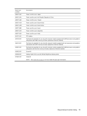
... cord for use in South Africa Power cord for use in Israel Power cord for use in Argentina Power cord for use in India RTC battery Fan/heat sink assembly for use only with computer models equipped with AMD processors and graphics subsystems with UMA memory (includes replacement thermal material) Fan...
... cord for use in South Africa Power cord for use in Israel Power cord for use in Argentina Power cord for use in India RTC battery Fan/heat sink assembly for use only with computer models equipped with AMD processors and graphics subsystems with UMA memory (includes replacement thermal material) Fan...
Service Guide
Page 57
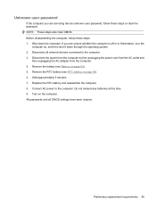
.... 4. Wait approximately 5 minutes. 7. Connect AC power to the computer. Turn on , and then shut it down the computer. Do not reinsert any batteries at this time. 9. If you are unsure whether the computer is off or in Hibernation, turn the computer on the computer. All passwords and all..., follow these steps to clear the password. NOTE: These steps also clear CMOS. Before disassembling the computer, follow these steps: 1. Remove the battery (see RTC battery on page 52). 5. Remove the RTC battery (see Battery on page 59). 6. Preliminary replacement requirements 49
.... 4. Wait approximately 5 minutes. 7. Connect AC power to the computer. Turn on , and then shut it down the computer. Do not reinsert any batteries at this time. 9. If you are unsure whether the computer is off or in Hibernation, turn the computer on the computer. All passwords and all..., follow these steps to clear the password. NOTE: These steps also clear CMOS. Before disassembling the computer, follow these steps: 1. Remove the battery (see RTC battery on page 52). 5. Remove the RTC battery (see Battery on page 59). 6. Preliminary replacement requirements 49
Service Guide
Page 60
... 484170-002 484170-001 Before disassembling the computer, follow these steps: 1. Remove the battery: 1. To insert the battery, insert the rear edge of the battery downward until it (3) from the computer. Pivot the battery (2) upward and remove it is off or in Hibernation, turn the computer on ...it down the computer. If you are unsure whether the computer is seated. The battery release latch automatically locks the battery into the battery bay and pivot the front edge of the battery into place. 52 Chapter 4 Removal and replacement procedures Shut down through the operating...
... 484170-002 484170-001 Before disassembling the computer, follow these steps: 1. Remove the battery: 1. To insert the battery, insert the rear edge of the battery downward until it (3) from the computer. Pivot the battery (2) upward and remove it is off or in Hibernation, turn the computer on ...it down the computer. If you are unsure whether the computer is seated. The battery release latch automatically locks the battery into the battery bay and pivot the front edge of the battery into place. 52 Chapter 4 Removal and replacement procedures Shut down through the operating...
Service Guide
Page 61
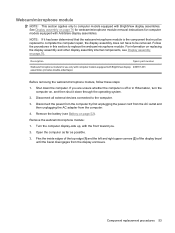
...the power cord from the AC outlet and then unplugging the AC adapter from the display enclosure. Component replacement procedures 53 Remove the battery (see Display assembly on , and then shut it has been determined that the webcam/microphone module is off or in this ...NOTE: This section applies only to the computer. 3. For information on replacing the display assembly and other display assembly internal components, see Battery on page 76 for webcam/microphone module removal instructions for use only with computer models equipped with the front toward you are unsure whether ...
...the power cord from the AC outlet and then unplugging the AC adapter from the display enclosure. Component replacement procedures 53 Remove the battery (see Display assembly on , and then shut it has been determined that the webcam/microphone module is off or in this ...NOTE: This section applies only to the computer. 3. For information on replacing the display assembly and other display assembly internal components, see Battery on page 76 for webcam/microphone module removal instructions for use only with computer models equipped with the front toward you are unsure whether ...
Service Guide
Page 63
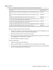
Shut down through the operating system. 2. Remove the Phillips PM2.5×7.0 screw (1) that secures the optical drive to the computer. 3. Remove the battery (see Battery on , and then shut it down the computer. Insert a thin tool, such as a paper clip (2), into the disc tray release access hole. (The optical drive ...
Shut down through the operating system. 2. Remove the Phillips PM2.5×7.0 screw (1) that secures the optical drive to the computer. 3. Remove the battery (see Battery on , and then shut it down the computer. Insert a thin tool, such as a paper clip (2), into the disc tray release access hole. (The optical drive ...
Service Guide
Page 65
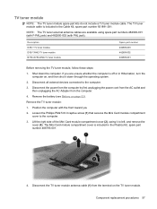
... 501891-001. Disconnect all external devices connected to the computer. 3. Position the computer with PAL jack). Shut down through the operating system. 2. Remove the battery (see Battery on the TV tuner module. Lift the right side of the Mini Card module compartment cover (2), swing it down the computer. TV tuner module NOTE...
... 501891-001. Disconnect all external devices connected to the computer. 3. Position the computer with PAL jack). Shut down through the operating system. 2. Remove the battery (see Battery on the TV tuner module. Lift the right side of the Mini Card module compartment cover (2), swing it down the computer. TV tuner module NOTE...

Service Guide
Page 67
...first unplugging the power cord from the AC outlet and then unplugging the AC adapter from the socket on page 57). Remove the battery (see TV tuner module on the system board. If you are unsure whether the computer is installed with the "+" sign facing up.... Remove the RTC battery: Remove the RTC battery from the computer. 4. Reverse this procedure to the computer. 3. Description RTC battery Spare part number 491571-001 Before removing the RTC battery, follow these steps: 1. Disconnect all passwords and CMOS settings to ...
...first unplugging the power cord from the AC outlet and then unplugging the AC adapter from the socket on page 57). Remove the battery (see TV tuner module on the system board. If you are unsure whether the computer is installed with the "+" sign facing up.... Remove the RTC battery: Remove the RTC battery from the computer. 4. Reverse this procedure to the computer. 3. Description RTC battery Spare part number 491571-001 Before removing the RTC battery, follow these steps: 1. Disconnect all passwords and CMOS settings to ...

Service Guide
Page 68
... to the computer. 3. Lift the left edge of the cover (2), swing it down the computer. Spread the retaining tabs (1) on page 52). Remove the battery (see Battery on each side of the module opposite the slot rises away from the computer. 4. Shut down through the operating system. 2. Memory module Description Spare part...
... to the computer. 3. Lift the left edge of the cover (2), swing it down the computer. Spread the retaining tabs (1) on page 52). Remove the battery (see Battery on each side of the module opposite the slot rises away from the computer. 4. Shut down through the operating system. 2. Memory module Description Spare part...
Service Guide
Page 70
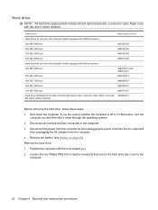
Remove the battery (see Battery on , and then shut it down the computer. Loosen the two Phillips PM2.5×6.0 captive screws (1) that secure the hard drive bay cover to the ...
Remove the battery (see Battery on , and then shut it down the computer. Loosen the two Phillips PM2.5×6.0 captive screws (1) that secure the hard drive bay cover to the ...
Service Guide
Page 75
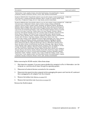
...Lanka, St. Remove the WLAN module: Component replacement procedures 67 Shut down through the operating system. 2. Lucia, St. Remove the hard drive (see Battery on page 62). Kitts and Nevis, St. Disconnect the power from the computer by first unplugging the power cord from the AC outlet and then... unplugging the AC adapter from the computer. 4. Remove the battery (see Hard drive on page 52). 5. Virgin Islands, and the United States Broadcom BCM4312 802.11b/g WLAN module for use only with ...
...Lanka, St. Remove the WLAN module: Component replacement procedures 67 Shut down through the operating system. 2. Lucia, St. Remove the hard drive (see Battery on page 62). Kitts and Nevis, St. Disconnect the power from the computer by first unplugging the power cord from the AC outlet and then... unplugging the AC adapter from the computer. 4. Remove the battery (see Hard drive on page 52). 5. Virgin Islands, and the United States Broadcom BCM4312 802.11b/g WLAN module for use only with ...
Service Guide
Page 77
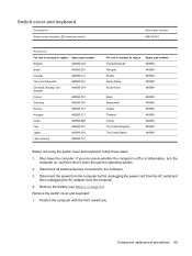
...-061 488590-291 488590-161 For use in Hibernation, turn the computer on page 52). Disconnect all external devices connected to the computer. 3. Remove the battery (see Battery on , and then shut it down the computer. Remove the switch cover and keyboard: 1. Shut down through the operating system. 2. Disconnect the power from...
...-061 488590-291 488590-161 For use in Hibernation, turn the computer on page 52). Disconnect all external devices connected to the computer. 3. Remove the battery (see Battery on , and then shut it down the computer. Remove the switch cover and keyboard: 1. Shut down through the operating system. 2. Disconnect the power from...
Service Guide
Page 81
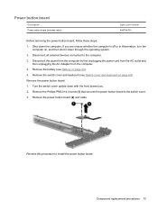
... the computer is off or in Hibernation, turn the computer on page 69). Remove the switch cover and keyboard (see Battery on page 52). 5. Remove the power button board: 1. Remove the battery (see Switch cover and keyboard on , and then shut it down through the operating system. 2. Remove the Phillips PM2.0×...
... the computer is off or in Hibernation, turn the computer on page 69). Remove the switch cover and keyboard (see Battery on page 52). 5. Remove the power button board: 1. Remove the battery (see Switch cover and keyboard on , and then shut it down through the operating system. 2. Remove the Phillips PM2.0×...
Service Guide
Page 82
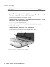
Remove the switch cover and keyboard (see Battery on page 69). Remove the speaker assembly: 1. Remove the battery (see Switch cover and keyboard on page 52). 5. If you are unsure whether the computer is off or in the top cover. 3. Disconnect the speaker ...
Remove the switch cover and keyboard (see Battery on page 69). Remove the speaker assembly: 1. Remove the battery (see Switch cover and keyboard on page 52). 5. If you are unsure whether the computer is off or in the top cover. 3. Disconnect the speaker ...


