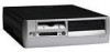
HP Compaq Business Desktop d500 Service Reference Guide, 5th Edition
Page 6
... 3-19 3.5.9 Fingerprint Identification Technology 3-19 3.6 Fault Notification and Recovery 3-20 3.6.1 Drive Protection System 3-20 3.6.2 Surge-Tolerant Power Supply 3-20 3.6.3 Thermal Sensor 3-20 4 Serial and Parallel ATA Drive Guidelines and Features 4.1 PATA and SATA Device Information 4-1 4.2 ATA ... Disassembly Preparation 5.1 Chassis Designations 5-1 5.1.1 Convertible Minitower (CMT 5-1 5.1.2 Small Form Factor (SFF 5-2 5.1.3 Ultra-Slim Desktop (USDT 5-2 5.2 Electrostatic Discharge Information 5-3 5.2.1 Generating Static 5-3 iv 336492-005 Service Reference Guide, d500
HP Compaq Business Desktop d500 Service Reference Guide, 5th Edition
Page 116
... to the inside of the following circumstances: ■ Power outage ■ Startup failure ■ Processor or power supply failure ■ Lost password 1. Then, secure the ... the Smart Cover Lock, position the lock so that secure the Smart Cover Lock to the Desktop Management Guide on the Documentation Library CD for more information about the Smart Cover Lock. Remove ...the computer access panel (Section 7.5, "Computer Access Panel"). Small Form Factor (SFF) Chassis 7.2 Unlocking the Smart Cover Lock If you will be removed. Once the solenoid has been...
HP Compaq Business Desktop d500 Service Reference Guide, 5th Edition
Page 130
...area to prevent them from interfering with the power supply fan. 4. Route this cable away from the top of the power supply to the back of the power supply and its fan access area. Keep the cable clear of the power supply fan. 3. Small Form Factor (SFF) Chassis 7.10.2 Cable Routing Ä ...CAUTION: The drive data and power cables must be kept clear of the power supply and the power supply fan to...
HP Compaq Business Desktop d500 Service Reference Guide, 5th Edition
Page 138
Small Form Factor (SFF) Chassis 7.11 Front I /O device cables from the system board: the front USB cable pair and the front audio cable. 4. Remove the power supply from its mount. To install the housing assembly, reverse the removal procedures. 7-24 336492-005 Service Reference Guide, d500 Disconnect the two I /O Devices 1.... that secure the I/O device to the chassis 1, then pull the device into the chassis 2 to free it from the chassis (Section 7.18, "Power Supply"). 5. Removal and Replacement Procedures- Remove the computer access panel (Section 7.5, "Computer Access Panel"). 3.
HP Compaq Business Desktop d500 Service Reference Guide, 5th Edition
Page 139
... from the system board. 4. Carefully cut the cable tie that secures the power switch cable to the power supply cable cable bundle. Ä CAUTION: Be careful when cutting the cable tie not to cut any cables. 5. Small Form Factor (SFF) Chassis 7.12 Power Switch Assembly 1. Remove the computer access panel (Section 7.5, "Computer Access Panel"). 3. Removal...
HP Compaq Business Desktop d500 Service Reference Guide, 5th Edition
Page 146
Small Form Factor (SFF) Chassis 7.17 Speaker 1. To install the speaker, reverse the removal procedures. 7-32 336492-005 Service Reference Guide, d500 Removal and Replacement Procedures- Rotate the drive cage to remove it. Remove the power supply from the system board. 6. Remove the computer access panel (...tie that secure the speaker to cut any cables. 7. Disconnect the speaker wire from the chassis (Section 7.18, "Power Supply"). 8. Remove the expansion card cage (Section 7.9, "Expansion Card Cage"). 5. Remove the two screws that secures the speaker cable to the...
HP Compaq Business Desktop d500 Service Reference Guide, 5th Edition
Page 147
... the computer and/or the AC outlet before opening the computer. 1. Remove the three screws that secures the power supply cable bundle to its upright position. 4. Removal and Replacement Procedures- Small Form Factor (SFF) Chassis 7.18 Power Supply Å WARNING: Voltage is always present on the system board when the computer is plugged into an...
HP Compaq Business Desktop d500 Service Reference Guide, 5th Edition
Page 228
... replacement 6-3 memory removal and replacement 6-8 minitower to desktop conversion 6-39 optical drive removal and replacement 6-20 padlock 6-4 PCI retainer latch removal and replacement 6-14 power supply removal and replacement 6-35 power switch assembly removal and replacement 6-25 preparation for Windows... replacement 8-13 drive cage USDT removal and replacement 8-23 drive positions CMT 6-17 SFF 7-15 drive, protecting 3-20 dual-state power button 3-6 E electrostatic discharge. See CMT country-specific power cord set requirements B-2 cover lock security, caution 3-16 cover lock, smart 3-16...
HP Compaq Business Desktop d500 Service Reference Guide, 5th Edition
Page 229
...slot cover CMT removal and replacement 6-10 SFF removal and replacement 7-11 external 3.5-inch drive SFF removal and replacement 7-20 F FailSafe Boot Block ROM 3-5 FailSafe Key caution 3-17 FailSafe key CMT 6-2 SFF 7-2 fan, power supply 5-7 FAT 32 to NTFS conversion 1-2 fault...pin assignments A-4 heatsink CMT removal and replacement 6-30 SFF removal and replacement 7-31 USDT removal and replacement 8-18 hood sensor CMT removal and replacement 6-3 SFF removal and replacement 7-3 HP Client Management Solutions 3-3 HP Client Manager 3-2 HP software. See infrared (IR) transceiver J jumper settings...
HP Compaq Business Desktop d500 Service Reference Guide, 5th Edition
Page 230
... cable layout 4-3 data cable pinouts 4-2 power cable pinouts 4-2 POST (Power-On Self-Test) 2-1 POST error messages C-1 to C-7 power button configuring 3-6 dual-state 3-6 power cord set requirements country specific B-2 general B-1 Power Management 3-7 power supply CMT removal and replacement 6-35 fan 5-7 SFF removal and replacement 7-33 USDT removal and replacement 8-19 power supply, surge-tolerant 3-20 power switch assembly CMT removal and replacement...
HP Compaq Business Desktop d500 Service Reference Guide, 5th Edition
Page 231
... 7-13 SFF battery 7-28 SFF cable lock 7-4 SFF chassis fan 7-27 SFF diskette drive bezel 7-7 SFF expansion card 7-11 SFF expansion card cage 7-9, 7-10 SFF expansion slot cover 7-11 SFF external 3.5-inch drive 7-20 SFF FailSafe key 7-2 SFF front bezel 7-6 SFF front drive bezel 7-7 SFF front I/O devices 7-24 SFF hard drive 7-22 SFF heatsink 7-31 SFF hood sensor 7-3 SFF memory 7-8 SFF optical drive 7-17 SFF padlock 7-4 SFF power supply 7-33 SFF power switch...
HP Compaq Business Desktop d500 Service Reference Guide, 5th Edition
Page 232
... SSM (System Software Manager) 3-3 static electricity 5-3 storage, Computer Setup heading 2-4 surge-tolerant power supply 3-20 system board CMT removal and replacement 6-26 designators E-1 SFF removal and replacement 7-26 USDT removal and replacement 8-26 system fan USDT removal and replacement ... sensor removal and replacement 7-3 memory removal and replacement 7-8 optical drive removal and replacement 7-17 padlock 7-4 power supply removal and replacement 7-33 power switch assembly removal and replacement 7-25 preparation for disassembly 7-1 riser card removal and replacement 7-10 Smart Cover...
HP Compaq Business Desktop d500 Service Reference Guide, 5th Edition
Page 233
... and replacement 8-13 MultiBay security catch 8-13 padlock 8-3 power supply removal and replacement 8-19 power switch assembly removal and replacement 8-17 preparation for disassembly ...HP Proactive Notification 3-4 HPQ Flash 3-4 PC Deployment 3-1 Remote Diagnostics Enabling Agent SoftPaq 2-18 ROMPaq images 3-4 Subscriber's Choice 3-4 support software 3-7 System Software Manager 3-3, 3-4, 3-6 World Wide Web addresses. See Web sites wrench, tamper resistant CMT 6-2 wrench, tamper-resistant 5-7 SFF 7-2 Service Reference Guide, d500 336492-005 Index-7 Index T tamper-proof screws CMT 6-2 SFF...