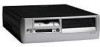
D530 Power Supply Removal - HP Compaq Business Desktop
D530 Power Supply Removal
Related Manual Pages


Similar Questions


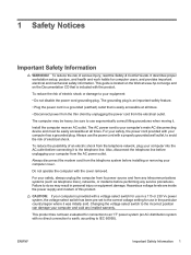
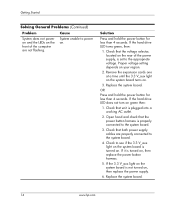
Power Supply Led And Lan Led Flashes Simultaneusly And Does Not Start
i have a problem power supply led and lan led flashes and the pc does not start, is it a power suppl...
i have a problem power supply led and lan led flashes and the pc does not start, is it a power suppl...
(Posted by ivan88880 12 years ago)

Assembly Take Aprt
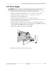
Power Supply Removal
(Posted by debardir 13 years ago)