100B All in One Disassembly - HP PC
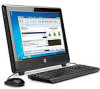
100B All in One Disassembly
Related Manual Pages


Similar Questions

How To Disassemble A Hp Touchsmart Iq504
(Posted by chargMOMDA 10 years ago)


How To Disassemble Pc, Remove And Install Hdd?
(Posted by addisonstan1 12 years ago)
Related Terms
The following terms were also used when searching for 100B All in One Disassembly - HP PC:- hp 1000 printer
- hp 1000 driver
- 1000 printer
- 100 driver
- 100 printer
- 1000 driver
- hp 100 printer
- 100b all-in-one pc
- 100b
- 100b aio
- 100b aio bios
- 100b aio pc
- 100b aio power cable
- 100b all in one bios password
- 100b all in one blue screen
- 100b all in one business pc
- 100b all in one desktop
- 100b all in one disassembly
- 100b all in one drivers
- 100b all in one factory restore
- 100b all in one hard drive replacement
- 100b all in one memory
- 100b all in one memory upgrade
- 100b all in one parts
- 100b all in one pc
- 100b all in one pc drivers
- 100b all in one pc manual
- 100b all in one pc memory upgrade
- 100b all in one pc ram upgrade
- 100b all in one pc series
- 100b all in one pc specs
- 100b all in one power adapter
- 100b all in one power supply
- 100b all in one ram
- 100b all in one ram upgrade
- 100b all in one specs
- 100b all in one support
- 100b all in-one computer price
- 100b all-in-one business pc
- 100b all-in-one desktop pc
- 100b all-in-one drivers
- 100b all-in-one memory
- 100b all-in-one pc drivers
- 100b all-in-one pc ethernet driver
- 100b all-in-one pc how to remove back cover
- 100b all-in-one pc manual
- 100b all-in-one pc memory upgrade
- 100b all-in-one pc pdf
- 100b all-in-one pc power cord
- 100b all-in-one pc price
- 100b all-in-one pc recovery download
- 100b all-in-one pc review
- 100b all-in-one pc specs
- 100b all-in-one pc upgrades
- 100b answers
- 100b build
- 100b computer
- 100b desktop
- 100b desktop computer
- 100b desktop review
- 100b disassembly
- 100b driver
- 100b drivers
- 100b error no boot disk detected
- 100b ethernet driver
- 100b hard drive replacement
- 100b hp
- 100b lan drivers
- 100b manual
- 100b media center
- 100b memory
- 100b memory install
- 100b memory module
- 100b memory upgrade
- 100b motherboard
- 100b parts
- 100b power adapter
- 100b power button
- 100b power cord
- 100b power supply
- 100b prices
- 100b ram upgrade
- 100b review
- 100b reviews
- 100b service manual
- 100b sound driver
- 100b specifications
- 100b specs
- 100b support
- 100b touchscreen
- 100b wall mount
- 100b windows xp
- 100b with 20 screen
- 100b xz812ut
- 100b xz812ut all in one pc
- 100b xz812ut all-in-one pc
- 100b xz813ut
- 100b xz813ut all in one pc
- 100b xz813ut all-in-one pc
- hp 1000
- hp 100b
- hp 100b aio
- hp 100b aio bios
- hp 100b aio pc
- hp 100b aio power cable
- hp 100b all in one bios password
- hp 100b all in one blue screen
- hp 100b all in one business pc
- hp 100b all in one desktop
- hp 100b all in one disassembly
- hp 100b all in one drivers
- hp 100b all in one factory restore
- hp 100b all in one hard drive replacement
- hp 100b all in one memory
- hp 100b all in one memory upgrade
- hp 100b all in one parts
- hp 100b all in one pc
- hp 100b all in one pc drivers
- hp 100b all in one pc manual
- hp 100b all in one pc memory upgrade
- hp 100b all in one pc ram upgrade
- hp 100b all in one pc series
- hp 100b all in one pc specs
- hp 100b all in one power adapter
- hp 100b all in one power supply
- hp 100b all in one ram
- hp 100b all in one ram upgrade
- hp 100b all in one specs
- hp 100b all in one support
- hp 100b all in-one computer price
- hp 100b all-in-one business pc
- hp 100b all-in-one desktop pc
- hp 100b all-in-one drivers
- hp 100b all-in-one memory
- hp 100b all-in-one pc
- hp 100b all-in-one pc drivers
- hp 100b all-in-one pc ethernet driver
- hp 100b all-in-one pc how to remove back cover
- hp 100b all-in-one pc manual
- hp 100b all-in-one pc memory upgrade
- hp 100b all-in-one pc pdf
- hp 100b all-in-one pc power cord
- hp 100b all-in-one pc price
- hp 100b all-in-one pc recovery download
- hp 100b all-in-one pc review
- hp 100b all-in-one pc specs
- hp 100b all-in-one pc upgrades
- hp 100b bios
- hp 100b computer
- hp 100b desktop
- hp 100b desktop computer
- hp 100b desktop review
- hp 100b disassembly
- hp 100b driver
- hp 100b drivers
- hp 100b error no boot disk detected
- hp 100b ethernet driver
- hp 100b hard drive replacement
- hp 100b lan drivers
- hp 100b manual
- hp 100b media center
- hp 100b memory
- hp 100b memory install
- hp 100b memory module
- hp 100b memory upgrade
- hp 100b motherboard
- hp 100b parts
- hp 100b pc
- hp 100b power adapter
- hp 100b power button
- hp 100b power cord
- hp 100b power supply
- hp 100b prices
- hp 100b ram
- hp 100b ram upgrade
- hp 100b review
- hp 100b reviews
- hp 100b service manual
- hp 100b sff
- hp 100b sound driver
- hp 100b specifications
- hp 100b specs
- hp 100b ssd
- hp 100b support
- hp 100b touchscreen
- hp 100b wall mount
- hp 100b windows xp
- hp 100b with 20 screen
- hp 100b xz812ut
- hp 100b xz812ut all in one pc
- hp 100b xz812ut all-in-one pc
- hp 100b xz813ut
- hp 100b xz813ut all in one pc
- hp 100b xz813ut all-in-one pc