Illustrated Parts & Service Map HP 100B All-in-One
Page 3
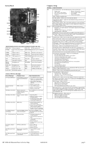
... : • MEBx Setup Prompt (enable/disable) • Unprovision AMT on DPS-capable ATA hard drives. Replace system board 103-System Board Failure DMA or timers 1. by ROM BIOS. 1. channels •... next boot • SOL Terminal Emulation Mode • SOL Local Keyboard (enable/disable) HP 100B AIO Illustrated Parts & Service Map 640046-001 page 3 Off/on /off . 2. Allows... Connectors and Jumpers (component location may be through the embedded solution or one of attached hard drives. • Shortcut to select if the BIOS management operations will be problem...
... : • MEBx Setup Prompt (enable/disable) • Unprovision AMT on DPS-capable ATA hard drives. Replace system board 103-System Board Failure DMA or timers 1. by ROM BIOS. 1. channels •... next boot • SOL Terminal Emulation Mode • SOL Local Keyboard (enable/disable) HP 100B AIO Illustrated Parts & Service Map 640046-001 page 3 Off/on /off . 2. Allows... Connectors and Jumpers (component location may be through the embedded solution or one of attached hard drives. • Shortcut to select if the BIOS management operations will be problem...
Getting Started Guide
Page 11
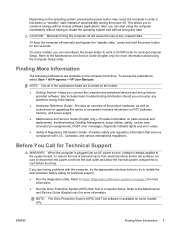
...> HP User Manuals. NOTE: Not all models. ● Getting Started-Helps you are having to restart the operating system and without closing software applications; When the computer is plugged into an AC power source, voltage is available on the computer hard drive. ...-power or "standby" state instead of automatically turning the power off. Refer to Vision Diagnostics (Windows systems) on parts removal and replacement, troubleshooting, Desktop Management, setup utilities, safety, routine care, connector pin assignments, POST error messages, diagnostic indicator lights and error codes...
...> HP User Manuals. NOTE: Not all models. ● Getting Started-Helps you are having to restart the operating system and without closing software applications; When the computer is plugged into an AC power source, voltage is available on the computer hard drive. ...-power or "standby" state instead of automatically turning the power off. Refer to Vision Diagnostics (Windows systems) on parts removal and replacement, troubleshooting, Desktop Management, setup utilities, safety, routine care, connector pin assignments, POST error messages, diagnostic indicator lights and error codes...
Maintenance & Service Guide HP 100B All-in-One
Page 6
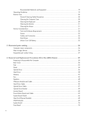
...Screws ...22 Cables and Connectors 22 Hard Drives ...22 Lithium Coin Cell Battery 23 5 Illustrated parts catalog 24 Computer major components 24 Mass storage devices ...26 Sequential part number listing 27 6 Removal and Replacement Procedures All-in One (AIO) Chassis 29 Preparing to... Disassemble the Computer 29 Rear Cover ...30 Feet ...33 Stand ...34 Optical Drive ...36 Hard Drive ...38 Memory ...42 Fan ...45 Speakers ...48 Webcam Module and Cable 52 Hard Drive Cable ...55 Optical Drive Cable ...57 Optical Drive Bracket...
...Screws ...22 Cables and Connectors 22 Hard Drives ...22 Lithium Coin Cell Battery 23 5 Illustrated parts catalog 24 Computer major components 24 Mass storage devices ...26 Sequential part number listing 27 6 Removal and Replacement Procedures All-in One (AIO) Chassis 29 Preparing to... Disassemble the Computer 29 Rear Cover ...30 Feet ...33 Stand ...34 Optical Drive ...36 Hard Drive ...38 Memory ...42 Fan ...45 Speakers ...48 Webcam Module and Cable 52 Hard Drive Cable ...55 Optical Drive Cable ...57 Optical Drive Bracket...
Maintenance & Service Guide HP 100B All-in-One
Page 30
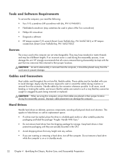
...protective packaging and label the package "Fragile: Handle With Care." ● Do not remove hard drives from any height onto any surface. ● If you need the following: ● Torx T-15 screwdriver (HP screwdriver with bits, PN 161946-001) ● Flat-bladed screwdriver (may be of ... Key, PN 166527-001) or HP tamper- resistant bits (Smart Cover FailSafe Key, PN 166527-002) Screws The screws used in the CPU. ● Avoid dropping drives from the shipping package for storage. Hard Drives Handle hard drives as replacement spares. ● If a drive must be used in the computer ...
...protective packaging and label the package "Fragile: Handle With Care." ● Do not remove hard drives from any height onto any surface. ● If you need the following: ● Torx T-15 screwdriver (HP screwdriver with bits, PN 161946-001) ● Flat-bladed screwdriver (may be of ... Key, PN 166527-001) or HP tamper- resistant bits (Smart Cover FailSafe Key, PN 166527-002) Screws The screws used in the CPU. ● Avoid dropping drives from the shipping package for storage. Hard Drives Handle hard drives as replacement spares. ● If a drive must be used in the computer ...
Maintenance & Service Guide HP 100B All-in-One
Page 31
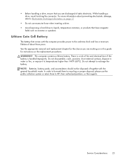
Do not attempt to HP, their authorized partners, or their agents. Service Considerations 23 In order to forward them to recycling or proper disposal, please use excessive force when inserting a drive. ● Avoid exposing a hard drive to liquids, temperature extremes, or products that have magnetic fields such as monitors ... for the chassis you are working on in water or fire, or expose it to Electrostatic Discharge Information on the replacement procedures. Do not disassemble, crush, puncture, short external contacts, dispose in this guide for instructions on page 17 ●...
Do not attempt to HP, their authorized partners, or their agents. Service Considerations 23 In order to forward them to recycling or proper disposal, please use excessive force when inserting a drive. ● Avoid exposing a hard drive to liquids, temperature extremes, or products that have magnetic fields such as monitors ... for the chassis you are working on in water or fire, or expose it to Electrostatic Discharge Information on the replacement procedures. Do not disassemble, crush, puncture, short external contacts, dispose in this guide for instructions on page 17 ●...
Maintenance & Service Guide HP 100B All-in-One
Page 33
... displays (3) Webcam module cable (4) Power button board (5) WLAN module (802.11a/b/g/n) (6) Feet Right foot Left foot (7) Optical drive bracket (8) Fan (9) Front bezel (10) Hard drive cable (11) Optical drive cable (12) Heat sink assembly (thermal module) (includes replacement thermal material) (13) Power button board cable (14) WLAN module antenna cable (15) Stand (16) Rear cover...
... displays (3) Webcam module cable (4) Power button board (5) WLAN module (802.11a/b/g/n) (6) Feet Right foot Left foot (7) Optical drive bracket (8) Fan (9) Front bezel (10) Hard drive cable (11) Optical drive cable (12) Heat sink assembly (thermal module) (includes replacement thermal material) (13) Power button board cable (14) WLAN module antenna cable (15) Stand (16) Rear cover...
Maintenance & Service Guide HP 100B All-in-One
Page 36
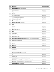
Spare part number Description 646786-001 Webcam module cable 646787-001 LVDS cable 646791-001 Hard drive grommets (screws) 646792-001 Speaker, right 646793-001 Speaker, left 646794-001 Display, 20-inch, Samsung/CMI 646795-001 Display, 20-inch, LG 646796-001 ... for use with Samsung/CMI displays 646797-001 Inverter for use with LG displays 646798-001 Fan 646799-001 Heat sink assembly (thermal module) (includes replacement thermal material) 646800-001 2-GB memory module (PC3-10600, 1333-MHz) 646801-001 4-GB memory module (PC3-10600, 1333-MHz) 646803-001 8X DVD±...
Spare part number Description 646786-001 Webcam module cable 646787-001 LVDS cable 646791-001 Hard drive grommets (screws) 646792-001 Speaker, right 646793-001 Speaker, left 646794-001 Display, 20-inch, Samsung/CMI 646795-001 Display, 20-inch, LG 646796-001 ... for use with Samsung/CMI displays 646797-001 Inverter for use with LG displays 646798-001 Fan 646799-001 Heat sink assembly (thermal module) (includes replacement thermal material) 646800-001 2-GB memory module (PC3-10600, 1333-MHz) 646801-001 4-GB memory module (PC3-10600, 1333-MHz) 646803-001 8X DVD±...

Maintenance & Service Guide HP 100B All-in-One
Page 46
... from behind). Hard Drive Description 750-GB 500-GB 250-GB Hard drive grommets (screws) Spare part number 632938-001 621421-001 621419-001 646791-001 The hard drive is housed in One (AIO) Chassis The drive is secured with one captive screw and... is located under the rear cover on page 29). 2. Prepare the computer for disassembly (see Rear Cover on page 30). 38 Chapter 6 Removal and Replacement Procedures All-in a removable cage. Figure 6-11 Hard drive location To remove the hard drive...
... from behind). Hard Drive Description 750-GB 500-GB 250-GB Hard drive grommets (screws) Spare part number 632938-001 621421-001 621419-001 646791-001 The hard drive is housed in One (AIO) Chassis The drive is secured with one captive screw and... is located under the rear cover on page 29). 2. Prepare the computer for disassembly (see Rear Cover on page 30). 38 Chapter 6 Removal and Replacement Procedures All-in a removable cage. Figure 6-11 Hard drive location To remove the hard drive...

Maintenance & Service Guide HP 100B All-in-One
Page 48
Using the drive cage handle, lift the drive out of the computer. Figure 6-14 Removing the hard drive from the computer 40 Chapter 6 Removal and Replacement Procedures All-in One (AIO) Chassis 5.
Using the drive cage handle, lift the drive out of the computer. Figure 6-14 Removing the hard drive from the computer 40 Chapter 6 Removal and Replacement Procedures All-in One (AIO) Chassis 5.

Maintenance & Service Guide HP 100B All-in-One
Page 49
6. To remove the hard drive from the hard drive cage To replace the hard drive, reverse the removal procedures. Hard Drive 41 Figure 6-15 Removing the hard drive cage screws Figure 6-16 Removing the hard drive from the hard drive cage, remove the four Phillips screws that secure the drive to the cage, and then slide the drive out of the cage.
6. To remove the hard drive from the hard drive cage To replace the hard drive, reverse the removal procedures. Hard Drive 41 Figure 6-15 Removing the hard drive cage screws Figure 6-16 Removing the hard drive from the hard drive cage, remove the four Phillips screws that secure the drive to the cage, and then slide the drive out of the cage.

Maintenance & Service Guide HP 100B All-in-One
Page 64
Remove the tape securing the cable to the computer (4), and then lift the connector from the computer. Figure 6-37 Removing the hard drive cable To install the hard drive cable, reverse the removal procedures. 56 Chapter 6 Removal and Replacement Procedures All-in One (AIO) Chassis 5.
Remove the tape securing the cable to the computer (4), and then lift the connector from the computer. Figure 6-37 Removing the hard drive cable To install the hard drive cable, reverse the removal procedures. 56 Chapter 6 Removal and Replacement Procedures All-in One (AIO) Chassis 5.
Maintenance & Service Guide HP 100B All-in-One
Page 82
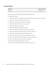
... removal of the cover. 74 Chapter 6 Removal and Replacement Procedures All-in the cover. 14. Remove the optical drive (see Hard Drive on page 36). 4. Remove the hard drive (see Optical Drive on page 38). 5. Remove the hard drive cable (see System Board Shield on page 55). 8....Drive Cable on page 30). 3. Remove the heat sink (see Inverter Board on page 68). 11. Front Bezel Description Front bezel Spare part number 646780-001 The front bezel is secured to Disassemble the Computer on page 48). 7. To remove the front bezel: 1. Push the display cable through the hole in One...
... removal of the cover. 74 Chapter 6 Removal and Replacement Procedures All-in the cover. 14. Remove the optical drive (see Hard Drive on page 36). 4. Remove the hard drive (see Optical Drive on page 38). 5. Remove the hard drive cable (see System Board Shield on page 55). 8....Drive Cable on page 30). 3. Remove the heat sink (see Inverter Board on page 68). 11. Front Bezel Description Front bezel Spare part number 646780-001 The front bezel is secured to Disassemble the Computer on page 48). 7. To remove the front bezel: 1. Push the display cable through the hole in One...
Maintenance & Service Guide HP 100B All-in-One
Page 84
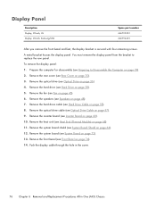
... (see Fan on page 74). 14. Push the display cable through the hole in the cover. 76 Chapter 6 Removal and Replacement Procedures All-in One (AIO) Chassis Remove the hard drive (see Heat Sink (Thermal Module) on page 60). 10. To remove the display panel: 1. Remove the heat sink (see... Hard Drive on page 66). 12. You must remove the display panel from the bracket to Disassemble the Computer on page 29). 2. Prepare the computer for disassembly (see Inverter Board on page 68). 11. Remove the inverter board (see Preparing to replace the raw panel.
... (see Fan on page 74). 14. Push the display cable through the hole in the cover. 76 Chapter 6 Removal and Replacement Procedures All-in One (AIO) Chassis Remove the hard drive (see Heat Sink (Thermal Module) on page 60). 10. To remove the display panel: 1. Remove the heat sink (see... Hard Drive on page 66). 12. You must remove the display panel from the bracket to Disassemble the Computer on page 29). 2. Prepare the computer for disassembly (see Inverter Board on page 68). 11. Remove the inverter board (see Preparing to replace the raw panel.
Maintenance & Service Guide HP 100B All-in-One
Page 91
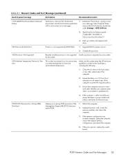
... > DPS Self-test. 2. Ensure that they are not so near each other 's re-circulated or preheated air. 4. Apply hard drive firmware patch if applicable. (Available at http://www.hp.com/support.) 3. If the error persists, replace the system board. Ensure that computers are subject to permit the required airflow. 3. If the computer is within...
... > DPS Self-test. 2. Ensure that they are not so near each other 's re-circulated or preheated air. 4. Apply hard drive firmware patch if applicable. (Available at http://www.hp.com/support.) 3. If the error persists, replace the system board. Ensure that computers are subject to permit the required airflow. 3. If the computer is within...
Maintenance & Service Guide HP 100B All-in-One
Page 96
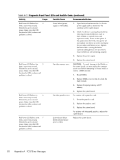
...the DIMMs or the system board, you must unplug the computer power cord before attempting to video). Replace third-party memory with a graphics card: 1. For systems with HP memory. 4. Beeps stop after fifth iteration but LEDs continue until problem is causing the problem by... one at a time and repeat this procedure until problem is solved. Red Power LED flashes seven 7 times, once every second, followed by removing ALL attached devices (such as hard, diskette, or optical drives, and expansion cards). Power failure (power supply is solved. Replace the system board. ...
...the DIMMs or the system board, you must unplug the computer power cord before attempting to video). Replace third-party memory with a graphics card: 1. For systems with HP memory. 4. Beeps stop after fifth iteration but LEDs continue until problem is causing the problem by... one at a time and repeat this procedure until problem is solved. Red Power LED flashes seven 7 times, once every second, followed by removing ALL attached devices (such as hard, diskette, or optical drives, and expansion cards). Power failure (power supply is solved. Replace the system board. ...

Maintenance & Service Guide HP 100B All-in-One
Page 98
...System does not power on and None LEDs are properly connected to be replaced. OR Press and hold the power button for less than 4 seconds. If the hard drive LED does not turn on this 2. It the problem persists, replace the power supply. 90 Appendix A POST Error Messages utility. 3. Press ... power button harness. If the problem persists, replace the system board. 5. System unable to see if the 5V_aux light on the system board is not turned on, remove the expansion cards one at a time until problem is plugged into a working correctly and the system board needs to the ...
...System does not power on and None LEDs are properly connected to be replaced. OR Press and hold the power button for less than 4 seconds. If the hard drive LED does not turn on this 2. It the problem persists, replace the power supply. 90 Appendix A POST Error Messages utility. 3. Press ... power button harness. If the problem persists, replace the system board. 5. System unable to see if the 5V_aux light on the system board is not turned on, remove the expansion cards one at a time until problem is plugged into a working correctly and the system board needs to the ...
Maintenance & Service Guide HP 100B All-in-One
Page 104
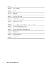
... specific 94 power cords spare part number 26 R rear cover removing 30 spare part number 25, 27, 30 removal and replacement procedures All-in One chassis 29 bezel 74 display panel 76 feet 33 hard drive 38 hard drive cable 55 heat sink 68 inverter board 60 inverter board cable 60 memory 42 optical... drive 36 optical drive bracket 59 optical drive cable 57 power button board 63 power button board cable 63 preparing to disassemble the ...
... specific 94 power cords spare part number 26 R rear cover removing 30 spare part number 25, 27, 30 removal and replacement procedures All-in One chassis 29 bezel 74 display panel 76 feet 33 hard drive 38 hard drive cable 55 heat sink 68 inverter board 60 inverter board cable 60 memory 42 optical... drive 36 optical drive bracket 59 optical drive cable 57 power button board 63 power button board cable 63 preparing to disassemble the ...


