Illustrated Parts & Service Map HP 100B All-in-One
Page 1
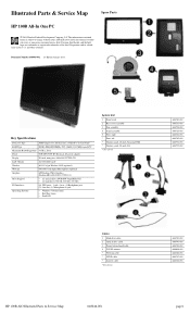
... be liable for technical or editorial errors or omissions contained herein. S. Illustrated Parts & Service Map Spare Parts HP 100B All-In One PC © 2011 Hewlett-Packard Development Company, L.P. Intel, Pentium, Intel Inside, and the Intel logo are trademarks...646784-001 646785-001 646794-001 646795-001 Cables 1 Hard drive cable 2 Optical drive cable 3 Power button board cable 4 WLAN antenna * Webcam cable * LVDS cable * Inverter cable *Not shown 646789-001 646790-001 646782-001 646806-001 646786-001 646787-001 646788-001 HP 100B AIO Illustrated Parts & Service Map 640046-001 ...
... be liable for technical or editorial errors or omissions contained herein. S. Illustrated Parts & Service Map Spare Parts HP 100B All-In One PC © 2011 Hewlett-Packard Development Company, L.P. Intel, Pentium, Intel Inside, and the Intel logo are trademarks...646784-001 646785-001 646794-001 646795-001 Cables 1 Hard drive cable 2 Optical drive cable 3 Power button board cable 4 WLAN antenna * Webcam cable * LVDS cable * Inverter cable *Not shown 646789-001 646790-001 646782-001 646806-001 646786-001 646787-001 646788-001 HP 100B AIO Illustrated Parts & Service Map 640046-001 ...
Illustrated Parts & Service Map HP 100B All-in-One
Page 3
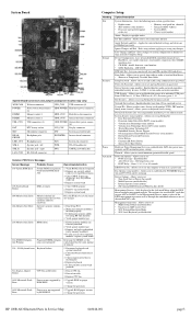
...Replace system board 103-System Board Failure DMA or timers 1. Verify proper module type. 3. Reseat fan cable. 3. Apply Defaults and Exit - model, firmware, serial number. • SATA Emulation - Boot... Allows you to turn on at Power-On (on next boot • SOL Terminal Emulation Mode • SOL Local Keyboard (enable/disable) HP 100B AIO Illustrated Parts & Service Map 640046-001...Board System Board Connectors and Jumpers (component location may be through the embedded solution or one of Embedded Security Device (some models) • NIC Option ROM Download (PXE,...
...Replace system board 103-System Board Failure DMA or timers 1. Verify proper module type. 3. Reseat fan cable. 3. Apply Defaults and Exit - model, firmware, serial number. • SATA Emulation - Boot... Allows you to turn on at Power-On (on next boot • SOL Terminal Emulation Mode • SOL Local Keyboard (enable/disable) HP 100B AIO Illustrated Parts & Service Map 640046-001...Board System Board Connectors and Jumpers (component location may be through the embedded solution or one of Embedded Security Device (some models) • NIC Option ROM Download (PXE,...
Maintenance & Service Guide HP 100B All-in-One
Page 6
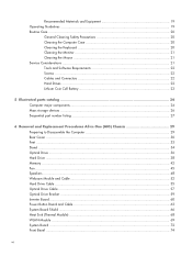
... parts catalog 24 Computer major components 24 Mass storage devices ...26 Sequential part number listing 27 6 Removal and Replacement Procedures All-in One (AIO) Chassis 29 Preparing to Disassemble the Computer 29 Rear Cover ...30 Feet ...33 Stand ...34 Optical Drive ...36 Hard Drive ...38... Memory ...42 Fan ...45 Speakers ...48 Webcam Module and Cable 52 Hard Drive Cable ...55 Optical Drive Cable ...57 Optical Drive Bracket ...59 Inverter Board ...60 Power Button Board and Cable 63 System Board Shield ...66 Heat Sink (Thermal Module) ...68 WLAN Module ...69...
... parts catalog 24 Computer major components 24 Mass storage devices ...26 Sequential part number listing 27 6 Removal and Replacement Procedures All-in One (AIO) Chassis 29 Preparing to Disassemble the Computer 29 Rear Cover ...30 Feet ...33 Stand ...34 Optical Drive ...36 Hard Drive ...38... Memory ...42 Fan ...45 Speakers ...48 Webcam Module and Cable 52 Hard Drive Cable ...55 Optical Drive Cable ...57 Optical Drive Bracket ...59 Inverter Board ...60 Power Button Board and Cable 63 System Board Shield ...66 Heat Sink (Thermal Module) ...68 WLAN Module ...69...
Maintenance & Service Guide HP 100B All-in-One
Page 37
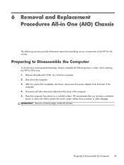
...sections provide information about disassembling various components of the computer. 5. 6 Removal and Replacement Procedures All-in One (AIO) Chassis The following steps in order, when opening the HP Pro All-in-One. 1. Shut down on a soft flat surface. Preparing to Disassemble the Computer 29 After the system ... shut down a blanket, towel, or other soft cloth to protect the touch screen surface from scratches or other attached cables from the back of the HP Pro Allin-One. Beware of the computer. 4. Disconnect all media (CD, DVD, etc.) from the back of sharp edges inside the...
...sections provide information about disassembling various components of the computer. 5. 6 Removal and Replacement Procedures All-in One (AIO) Chassis The following steps in order, when opening the HP Pro All-in-One. 1. Shut down on a soft flat surface. Preparing to Disassemble the Computer 29 After the system ... shut down a blanket, towel, or other soft cloth to protect the touch screen surface from scratches or other attached cables from the back of the HP Pro Allin-One. Beware of the computer. 4. Disconnect all media (CD, DVD, etc.) from the back of sharp edges inside the...

Maintenance & Service Guide HP 100B All-in-One
Page 72
... Be careful not to Disassemble the Computer on page 30). 3. Figure 6-45 Removing the power button board 5. Lift the board as far as the cables allow, and then disconnect the two cables from the board. Prepare the computer for disassembly (see Rear Cover on page 29). 2....damage the cables when disconnecting them from the board (3). Do not pull on the wires. Remove the board from the power button board (1) and the system board (2). 64 Chapter 6 Removal and Replacement Procedures All-in One (AIO) Chassis To remove the power button board cable: 1. 4. Disconnect the cable from the ...
... Be careful not to Disassemble the Computer on page 30). 3. Figure 6-45 Removing the power button board 5. Lift the board as far as the cables allow, and then disconnect the two cables from the board. Prepare the computer for disassembly (see Rear Cover on page 29). 2....damage the cables when disconnecting them from the board (3). Do not pull on the wires. Remove the board from the power button board (1) and the system board (2). 64 Chapter 6 Removal and Replacement Procedures All-in One (AIO) Chassis To remove the power button board cable: 1. 4. Disconnect the cable from the ...
Maintenance & Service Guide HP 100B All-in-One
Page 74
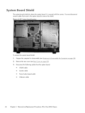
... the system board: ● WLAN cable ● Inverter cable ● Power button board cable ● Webcam cable 66 Chapter 6 Removal and Replacement Procedures All-in One (AIO) Chassis Remove the rear cover (see Preparing to remove the shield. Prepare the computer for disassembly (see Rear Cover on page 29). 2. System Board Shield ...
... the system board: ● WLAN cable ● Inverter cable ● Power button board cable ● Webcam cable 66 Chapter 6 Removal and Replacement Procedures All-in One (AIO) Chassis Remove the rear cover (see Preparing to remove the shield. Prepare the computer for disassembly (see Rear Cover on page 29). 2. System Board Shield ...


