
Manual
Page 1
MSH61PI LGA1155 socket motherboard for Intel® Core™ i3 / Core™ i5 Core™ i7 processors/ Intel® Pentium® series processors User's Manual Rev. 1001
MSH61PI LGA1155 socket motherboard for Intel® Core™ i3 / Core™ i5 Core™ i7 processors/ Intel® Pentium® series processors User's Manual Rev. 1001
Manual
Page 3
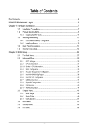
Table of Contents Box Contents...4 MSH61PI Motherboard Layout 5 Chapter 1 Hardware Installation 7 1-1 Installation Precautions 7 1-2 Product Specifications 8 1-3-2 Installing the CPU Cooler 11 1-4 Installing the Memory 12 1-4-1 Dual Channel Memory Configuration 12 1-4-2 Installing a Memory 13 1-5 ...
Table of Contents Box Contents...4 MSH61PI Motherboard Layout 5 Chapter 1 Hardware Installation 7 1-1 Installation Precautions 7 1-2 Product Specifications 8 1-3-2 Installing the CPU Cooler 11 1-4 Installing the Memory 12 1-4-1 Dual Channel Memory Configuration 12 1-4-2 Installing a Memory 13 1-5 ...

Manual
Page 4
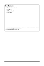
Box Contents MSH61PI motherboard Driver CD Two SATA cables I/O Shield • The box contents above are subject to change without notice. • The motherboard image is for reference only and the actual items shall depend on the product package you obtain. The box contents are for reference only. - 4 -
Box Contents MSH61PI motherboard Driver CD Two SATA cables I/O Shield • The box contents above are subject to change without notice. • The motherboard image is for reference only and the actual items shall depend on the product package you obtain. The box contents are for reference only. - 4 -
Manual
Page 5
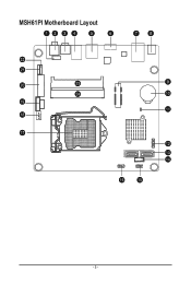
MSH61PI Motherboard Layout - 5 -
MSH61PI Motherboard Layout - 5 -

Manual
Page 7
MSH61PI LGA1155 socket motherboard for Intel® Core™ i3 / Core™ i5 Core™ i7 processors/ Intel® Pentium® series processors User's Manual Rev. 1001
MSH61PI LGA1155 socket motherboard for Intel® Core™ i3 / Core™ i5 Core™ i7 processors/ Intel® Pentium® series processors User's Manual Rev. 1001
Manual
Page 9
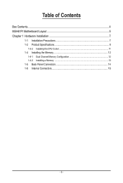
Table of Contents Box Contents...4 MSH61PI Motherboard Layout 5 Chapter 1 Hardware Installation 7 1-1 Installation Precautions 7 1-2 Product Specifications 8 1-3-2 Installing the CPU Cooler 11 1-4 Installing the Memory 12 1-4-1 Dual Channel Memory Configuration 12 1-4-2 Installing a Memory 13 1-5 Back Panel Connectors 14 1-6 Internal Connectors 16 - 3 -
Table of Contents Box Contents...4 MSH61PI Motherboard Layout 5 Chapter 1 Hardware Installation 7 1-1 Installation Precautions 7 1-2 Product Specifications 8 1-3-2 Installing the CPU Cooler 11 1-4 Installing the Memory 12 1-4-1 Dual Channel Memory Configuration 12 1-4-2 Installing a Memory 13 1-5 Back Panel Connectors 14 1-6 Internal Connectors 16 - 3 -
Manual
Page 10
Box Contents MSH61PI motherboard Driver CD Two SATA cables I/O Shield • The box contents above are subject to change without notice. • The motherboard image is for reference only and the actual items shall depend on the product package you obtain. The box contents are for reference only. - 4 -
Box Contents MSH61PI motherboard Driver CD Two SATA cables I/O Shield • The box contents above are subject to change without notice. • The motherboard image is for reference only and the actual items shall depend on the product package you obtain. The box contents are for reference only. - 4 -

Manual
Page 11
MSH61PI Motherboard Layout - 5 -
MSH61PI Motherboard Layout - 5 -
Manual
Page 13
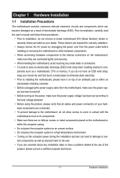
... object to eliminate static electricity. • Prior to the internal connectors on the computer power during the installation process can become damaged as a motherboard, CPU or memory. If you do not have it on top of the product, please consult a certified computer technician. - 7 - Prior...these procedures: • Prior to installation, do not allow screws to come in a high-temperature environment. • Turning on the motherboard, make sure the power supply voltage has been set according to the local voltage standard. • Before using the product, please verify ...
... object to eliminate static electricity. • Prior to the internal connectors on the computer power during the installation process can become damaged as a motherboard, CPU or memory. If you do not have it on top of the product, please consult a certified computer technician. - 7 - Prior...these procedures: • Prior to installation, do not allow screws to come in a high-temperature environment. • Turning on the motherboard, make sure the power supply voltage has been set according to the local voltage standard. • Before using the product, please verify ...
Manual
Page 16
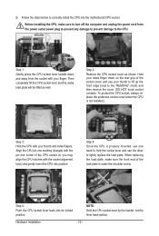
... one corner of the CPU socket (or you may align the CPU notches with the socket alignment keys) and gently insert the CPU into the motherboard CPU socket. NOTE: Hold the CPU socket lever by the handle, not the lever base portion. Before installing the CPU, make sure the front end...
... one corner of the CPU socket (or you may align the CPU notches with the socket alignment keys) and gently insert the CPU into the motherboard CPU socket. NOTE: Hold the CPU socket lever by the handle, not the lever base portion. Before installing the CPU, make sure the front end...

Manual
Page 17
...may damage the CPU. - 11 - Step 6: Finally, attach the power connector of the CPU cooler to correctly install the CPU cooler on the motherboard. (The following procedure uses Intel® boxed cooler as the picture above shows, the installation is for instructions on installing the cooler.) Step 5: ...the arrow is for removing the cooler, and the opposite direction is complete. Step 4: You should hear a "click" when pushing down on the motherboard. Step 2: Before installing the cooler, note the direction of the arrow sign on the male push pin. (Turning the push pin along the ...
...may damage the CPU. - 11 - Step 6: Finally, attach the power connector of the CPU cooler to correctly install the CPU cooler on the motherboard. (The following procedure uses Intel® boxed cooler as the picture above shows, the installation is for instructions on installing the cooler.) Step 5: ...the arrow is for removing the cooler, and the opposite direction is complete. Step 4: You should hear a "click" when pushing down on the motherboard. Step 2: Before installing the cooler, note the direction of the arrow sign on the male push pin. (Turning the push pin along the ...
Manual
Page 18
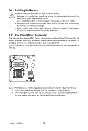
...DDR3 memory module is installed. 2. If you begin to insert the memory, switch the direction. 1-4-1 Dual Channel Memory Configuration This motherboard provides two DDR3 memory sockets and supports Dual Channel Technology. After the memory is installed, the BIOS will double the original memory bandwidth...channel has two memory sockets as following: SODIMMB1 SODIMMA1 Due to CPU limitations, read the following guidelines before installing the memory to GIGABYTE's website for optimum performance. The two DDR3 memory sockets are unable to install the memory: • Make sure that memory ...
...DDR3 memory module is installed. 2. If you begin to insert the memory, switch the direction. 1-4-1 Dual Channel Memory Configuration This motherboard provides two DDR3 memory sockets and supports Dual Channel Technology. After the memory is installed, the BIOS will double the original memory bandwidth...channel has two memory sockets as following: SODIMMB1 SODIMMA1 Due to CPU limitations, read the following guidelines before installing the memory to GIGABYTE's website for optimum performance. The two DDR3 memory sockets are unable to install the memory: • Make sure that memory ...
Manual
Page 19
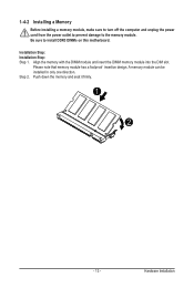
Installation Step: Installation Step: Step 1. Please note that memory module has a foolproof insertion design. 1-4-2 Installing a Memory Before installing a memory module, make sure to turn off the computer and unplug the power cord from the power outlet to prevent damage to install DDR3 DIMMs on this motherboard. Be sure to the memory module. Push down the memory and seat it firmly. 1 2 - 13 - Hardware Installation Step 2. A memory module can be installed In only one direction. Align the memory with the DIMM module and insert the DIMM memory module into the DIM slot.
Installation Step: Installation Step: Step 1. Please note that memory module has a foolproof insertion design. 1-4-2 Installing a Memory Before installing a memory module, make sure to turn off the computer and unplug the power cord from the power outlet to prevent damage to install DDR3 DIMMs on this motherboard. Be sure to the memory module. Push down the memory and seat it firmly. 1 2 - 13 - Hardware Installation Step 2. A memory module can be installed In only one direction. Align the memory with the DIMM module and insert the DIMM memory module into the DIM slot.

Manual
Page 21
... is occurring • When removing the cable connected to a back panel connector, first remove the cable from your device and then remove it from the motherboard. • When removing the cable, pull it side to side to prevent an electrical short inside the cable connector. Hardware Installation - 15 - Do not rock...
... is occurring • When removing the cable connected to a back panel connector, first remove the cable from your device and then remove it from the motherboard. • When removing the cable, pull it side to side to prevent an electrical short inside the cable connector. Hardware Installation - 15 - Do not rock...
Manual
Page 22
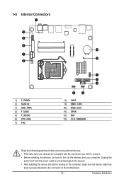
... devices and your devices are compliant with the connectors you wish to connect. • Before installing the devices, be sure to the connector on the motherboard. - 16 - Hardware Installation 1-6 Internal Connectors 1) F_PANEL 2) SATA1/2 3) HDD_PWR 4) F_USB1 5) F_AUDIO 6) CPU_FAN 7) FPD 8) LVDS 9) DMIC_CON 10) WEB_CON 11) SPEK 12) BAT 13) CLR_CMOSHW Read the following...
... devices and your devices are compliant with the connectors you wish to connect. • Before installing the devices, be sure to the connector on the motherboard. - 16 - Hardware Installation 1-6 Internal Connectors 1) F_PANEL 2) SATA1/2 3) HDD_PWR 4) F_USB1 5) F_AUDIO 6) CPU_FAN 7) FPD 8) LVDS 9) DMIC_CON 10) WEB_CON 11) SPEK 12) BAT 13) CLR_CMOSHW Read the following...
Manual
Page 25
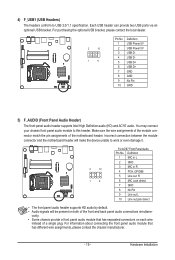
... bracket, please contact the local dealer. nector match the pin assignments of a single plug. Incorrect connection between the Smart module Card Reader connector and the motherboard header will be present on each panel audio module wire that has different wire assignments, please contact the chassis manufacturer. You may connect your chassis...
... bracket, please contact the local dealer. nector match the pin assignments of a single plug. Incorrect connection between the Smart module Card Reader connector and the motherboard header will be present on each panel audio module wire that has different wire assignments, please contact the chassis manufacturer. You may connect your chassis...
Manual
Page 26
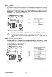
... optimum heat dissipation, it in damage to the display panel. Pin No. Overheating may hang. • These fan headers are not configuration jumper blocks. The motherboard supports CPU fan speed control, which requires the use this interface internally. Pin No. When connecting a fan cable, be installed inside the chassis. Do not... FPD specification. Most fan headers possess a foolproof insertion design. The headers conform to prevent your CPU and system from overheating. 6) CPU_FAN (CPU Fan Headers) The motherboard has a 4-pin CPU fan header (CPU_FAN) headers.
... optimum heat dissipation, it in damage to the display panel. Pin No. Overheating may hang. • These fan headers are not configuration jumper blocks. The motherboard supports CPU fan speed control, which requires the use this interface internally. Pin No. When connecting a fan cable, be installed inside the chassis. Do not... FPD specification. Most fan headers possess a foolproof insertion design. The headers conform to prevent your CPU and system from overheating. 6) CPU_FAN (CPU Fan Headers) The motherboard has a 4-pin CPU fan header (CPU_FAN) headers.
Manual
Page 30
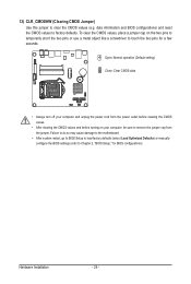
13) CLR_CMOSHW (Clearing CMOS Jumper) Use this jumper to Chapter 2, "BIOS Setup," for a few seconds. Failure to do so may cause damage to the motherboard. • After system restart, go to BIOS Setup to load factory defaults (select Load Optimized Defaults) or manually configure the BIOS settings (refer to clear ...
13) CLR_CMOSHW (Clearing CMOS Jumper) Use this jumper to Chapter 2, "BIOS Setup," for a few seconds. Failure to do so may cause damage to the motherboard. • After system restart, go to BIOS Setup to load factory defaults (select Load Optimized Defaults) or manually configure the BIOS settings (refer to clear ...
Manual
Page 31
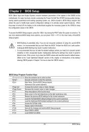
... settings or to activate certain system features. Inadequately altering the settings may result in system malfunction. • It is turned off, the battery on the motherboard. BIOS Setup Chapter 2 BIOS Setup BIOS (Basic Input and Output System) records hardware parameters of the system in the CMOS on the... motherboard supplies the necessary power to the CMOS to keep the configuration values in the CMOS. To access the BIOS Setup program, press the key during...
... settings or to activate certain system features. Inadequately altering the settings may result in system malfunction. • It is turned off, the battery on the motherboard. BIOS Setup Chapter 2 BIOS Setup BIOS (Basic Input and Output System) records hardware parameters of the system in the CMOS on the... motherboard supplies the necessary power to the CMOS to keep the configuration values in the CMOS. To access the BIOS Setup program, press the key during...


