
Manual
Page 1
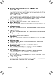
...Follow the steps below to the SATA disk. • Supported operating systems include Windows 7 and Windows Vista. • If you have and the BIOS version. - 1 - CMOS Setup Utility-Copyright (C) 1984-2011 Award Software Integrated Peripherals eXtreme Hard Drive (XHD) PCH SATA Control Mode OROM UI ...: Previous Values +/-/PU/PD: Value F10: Save F6: Fail-Safe Defaults ESC: Exit F1: General Help F7: Optimized Defaults The BIOS Setup menus described here may differ from the exact settings for storing your computer and press to the SATA disk 4. Installing the operating ...
...Follow the steps below to the SATA disk. • Supported operating systems include Windows 7 and Windows Vista. • If you have and the BIOS version. - 1 - CMOS Setup Utility-Copyright (C) 1984-2011 Award Software Integrated Peripherals eXtreme Hard Drive (XHD) PCH SATA Control Mode OROM UI ...: Previous Values +/-/PU/PD: Value F10: Save F6: Fail-Safe Defaults ESC: Exit F1: General Help F7: Optimized Defaults The BIOS Setup menus described here may differ from the exact settings for storing your computer and press to the SATA disk 4. Installing the operating ...

Manual
Page 2
... Install" function of the motherboard driver disk to install the operating system. Installing the operating system and drivers to the SATA disk: After setting the BIOS, you can begin to install all motherboard drivers, including the Intel Rapid Storage Technology driver. English 3. Launching the Intel Rapid Storage Technology utility to open...
... Install" function of the motherboard driver disk to install the operating system. Installing the operating system and drivers to the SATA disk: After setting the BIOS, you can begin to install all motherboard drivers, including the Intel Rapid Storage Technology driver. English 3. Launching the Intel Rapid Storage Technology utility to open...

User Manual
Page 3
... of documentations: For quick set-up of the motherboard is the property of this manual may be made by GIGABYTE without GIGABYTE's prior written permission. Example: Changes to assist in any form or by copyright laws and is 1.0. For product-related ...information, check on our website at: http://www.gigabyte.com Identifying Your Motherboard Revision The revision number on your motherboard revision before updating motherboard BIOS, drivers, or when looking for technical information. Copyright © 2011 GIGA-BYTE TECHNOLOGY...
... of documentations: For quick set-up of the motherboard is the property of this manual may be made by GIGABYTE without GIGABYTE's prior written permission. Example: Changes to assist in any form or by copyright laws and is 1.0. For product-related ...information, check on our website at: http://www.gigabyte.com Identifying Your Motherboard Revision The revision number on your motherboard revision before updating motherboard BIOS, drivers, or when looking for technical information. Copyright © 2011 GIGA-BYTE TECHNOLOGY...
User Manual
Page 4
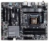
Table of Contents Box Contents...6 Optional Items...6 GA-Z68XP-UD4 Motherboard Layout 7 GA-Z68XP-UD4 Motherboard Block Diagram 8 Chapter 1 Hardware Installation 9 1-1 Installation Precautions 9 1-2 Product Specifications 10 1-3 Installing the CPU and CPU Cooler ...NVIDIA SLI Configuration 19 1-7 Back Panel Connectors 20 1-8 Internal Connectors 22 Chapter 2 BIOS Setup 33 2-1 Startup Screen 34 2-2 The Main Menu 35 2-3 MB Intelligent Tweaker(M.I.T 37 2-4 Standard CMOS Features 46 2-5 Advanced BIOS Features 48 2-6 Integrated Peripherals 50 2-7 Power Management Setup 53 2-8 PC Health ...
Table of Contents Box Contents...6 Optional Items...6 GA-Z68XP-UD4 Motherboard Layout 7 GA-Z68XP-UD4 Motherboard Block Diagram 8 Chapter 1 Hardware Installation 9 1-1 Installation Precautions 9 1-2 Product Specifications 10 1-3 Installing the CPU and CPU Cooler ...NVIDIA SLI Configuration 19 1-7 Back Panel Connectors 20 1-8 Internal Connectors 22 Chapter 2 BIOS Setup 33 2-1 Startup Screen 34 2-2 The Main Menu 35 2-3 MB Intelligent Tweaker(M.I.T 37 2-4 Standard CMOS Features 46 2-5 Advanced BIOS Features 48 2-6 Integrated Peripherals 50 2-7 Power Management Setup 53 2-8 PC Health ...

User Manual
Page 5
... 62 3-4 Contact...63 3-5 System...63 3-6 Download Center 64 3-7 New Utilities...64 Chapter 4 Unique Features 65 4-1 Xpress Recovery2 65 4-2 BIOS Update Utilities 68 4-2-1 Updating the BIOS with the Q-Flash Utility 68 4-2-2 Updating the BIOS with the @BIOS Utility 71 4-3 EasyTune 6...72 4-4 Dynamic Energy Saver™ 2 73 4-5 Q-Share...75 4-6 Smart 6™ ...76 4-7 Auto Green...80 4-8 eXtreme...
... 62 3-4 Contact...63 3-5 System...63 3-6 Download Center 64 3-7 New Utilities...64 Chapter 4 Unique Features 65 4-1 Xpress Recovery2 65 4-2 BIOS Update Utilities 68 4-2-1 Updating the BIOS with the Q-Flash Utility 68 4-2-2 Updating the BIOS with the @BIOS Utility 71 4-3 EasyTune 6...72 4-4 Dynamic Energy Saver™ 2 73 4-5 Q-Share...75 4-6 Smart 6™ ...76 4-7 Auto Green...80 4-8 eXtreme...
User Manual
Page 8
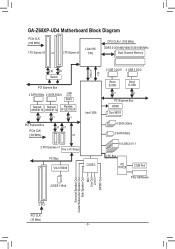
GA-Z68XP-UD4 Motherboard Block Diagram PCIe CLK (100 MHz) 1 PCI Express x16 or 2 PCI Express x8 LGA1155 CPU CPU CLK+/- (100 MHz) DDR3 2133/1866/1600/1333/... to PCI Bridge PCI Bus VIA VT6308 CODEC 2 IEEE 1394a DMI 2.0 FDI 2 USB 3.0/2.0 2 USB 3.0/2.0 Etron EJ168 Etron EJ168 x1 x1 PCI Express Bus HDMI Dual BIOS 4 SATA 3Gb/s 2 SATA 6Gb/s 14 USB 2.0/1.1 LPC Bus iTE IT8728 COM Port PS/2 KB/Mouse Surround Speaker Out Center/Subwoofer Speaker Out Side Speaker Out...
GA-Z68XP-UD4 Motherboard Block Diagram PCIe CLK (100 MHz) 1 PCI Express x16 or 2 PCI Express x8 LGA1155 CPU CPU CLK+/- (100 MHz) DDR3 2133/1866/1600/1333/... to PCI Bridge PCI Bus VIA VT6308 CODEC 2 IEEE 1394a DMI 2.0 FDI 2 USB 3.0/2.0 2 USB 3.0/2.0 Etron EJ168 Etron EJ168 x1 x1 PCI Express Bus HDMI Dual BIOS 4 SATA 3Gb/s 2 SATA 6Gb/s 14 USB 2.0/1.1 LPC Bus iTE IT8728 COM Port PS/2 KB/Mouse Surround Speaker Out Center/Subwoofer Speaker Out Side Speaker Out...
User Manual
Page 12
...x 32 Mbit flash ŠŠ Use of licensed AWARD BIOS ŠŠ Support for DualBIOS™ ŠŠ PnP 1.0a, DMI 2.0, SM BIOS 2.4, ACPI 1.0b Unique Features ŠŠ Support for @BIOS ŠŠ Support for Q-Flash ŠŠ Support for Xpress BIOS Rescue ŠŠ Support for Download Center ŠŠ... for TouchBIOS ŠŠ Support for Microsoft® Windows 7/Vista/XP Form Factor ŠŠ ATX Form Factor; 30.5cm x 24.4cm * GIGABYTE reserves the right to make any changes to the integrated graphics port on the CPU/system cooler you install.
...x 32 Mbit flash ŠŠ Use of licensed AWARD BIOS ŠŠ Support for DualBIOS™ ŠŠ PnP 1.0a, DMI 2.0, SM BIOS 2.4, ACPI 1.0b Unique Features ŠŠ Support for @BIOS ŠŠ Support for Q-Flash ŠŠ Support for Xpress BIOS Rescue ŠŠ Support for Download Center ŠŠ... for TouchBIOS ŠŠ Support for Microsoft® Windows 7/Vista/XP Form Factor ŠŠ ATX Form Factor; 30.5cm x 24.4cm * GIGABYTE reserves the right to make any changes to the integrated graphics port on the CPU/system cooler you install.

User Manual
Page 16
...Two Modules Four Modules DDR3_4 - For optimum performance, when enabling Dual Channel mode with two or four memory modules, it is installed, the BIOS will double the original memory bandwidth. A memory module can be used . It is installed. 2. If you are divided into two channels... and each channel has two memory sockets as following guidelines before installing the memory to GIGABYTE's website for the latest supported memory speeds and memory modules.) •• Always turn off the computer and unplug the power cord...
...Two Modules Four Modules DDR3_4 - For optimum performance, when enabling Dual Channel mode with two or four memory modules, it is installed, the BIOS will double the original memory bandwidth. A memory module can be used . It is installed. 2. If you are divided into two channels... and each channel has two memory sockets as following guidelines before installing the memory to GIGABYTE's website for the latest supported memory speeds and memory modules.) •• Always turn off the computer and unplug the power cord...
User Manual
Page 18
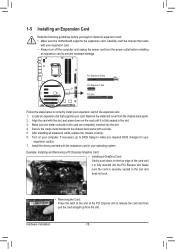
... to correctly install your expansion card in the expansion slot. 111 Locate an expansion slot that came with your card. If necessary, go to BIOS Setup to the chassis back panel with the expansion card in your computer. Example: Installing and Removing a PCI Express Graphics Card: • ...cord from the slot. Make sure the card is fully inserted into the slot. 444 Secure the card's metal bracket to make any required BIOS changes for your expansion card(s). 777 Install the driver provided with a screw. 555 After installing all expansion cards, replace the chassis cover(s)....
... to correctly install your expansion card in the expansion slot. 111 Locate an expansion slot that came with your card. If necessary, go to BIOS Setup to the chassis back panel with the expansion card in your computer. Example: Installing and Removing a PCI Express Graphics Card: • ...cord from the slot. Make sure the card is fully inserted into the slot. 444 Secure the card's metal bracket to make any required BIOS changes for your expansion card(s). 777 Install the driver provided with a screw. 555 After installing all expansion cards, replace the chassis cover(s)....
User Manual
Page 24
.... Replace the battery when the battery voltage drops to a low level, or the CMOS values may not be sure to keep the values (such as BIOS configurations, date, and time information) in the correct orientation (the black connector wire is replaced with local environmental regulations. When connecting a fan cable, be accurate...
.... Replace the battery when the battery voltage drops to a low level, or the CMOS values may not be sure to keep the values (such as BIOS configurations, date, and time information) in the correct orientation (the black connector wire is replaced with local environmental regulations. When connecting a fan cable, be accurate...

User Manual
Page 27
... indicate the problem. You may differ by issuing a beep code. If a problem is operating. When connecting your system using the power switch (refer to Chapter 2, "BIOS Setup," "Power Management Setup," for information about beep codes. •• HD (Hard Drive Activity LED, Blue) Connects to the hard drive activity LED on...
... indicate the problem. You may differ by issuing a beep code. If a problem is operating. When connecting your system using the power switch (refer to Chapter 2, "BIOS Setup," "Power Management Setup," for information about beep codes. •• HD (Hard Drive Activity LED, Blue) Connects to the hard drive activity LED on...

User Manual
Page 29
... via an UG T optional USB bracket. Definition 1 VBUS 11 D2+ 2 SSRX1- 12 D2- 3 SSRX1+ 13 GND 4 GND 14 SSTX2+ 5 SSTX1- 15 SSTX2- 6 SSTX1+ 16 GND BIOS 7 GND 17 SSRX2+ DB_PORT 8 D1- 18 SSRX2- 9 D1+ 19 VBUS 10 NC 20 No Pin When the system is in S4/S5 mode, only the...
... via an UG T optional USB bracket. Definition 1 VBUS 11 D2+ 2 SSRX1- 12 D2- 3 SSRX1+ 13 GND 4 GND 14 SSTX2+ 5 SSTX1- 15 SSTX2- 6 SSTX1+ 16 GND BIOS 7 GND 17 SSRX2+ DB_PORT 8 D1- 18 SSRX2- 9 D1+ 19 VBUS 10 NC 20 No Pin When the system is in S4/S5 mode, only the...
User Manual
Page 30
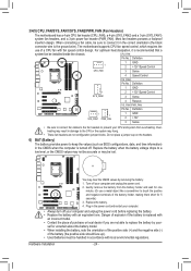
...Ensure that the cable is securely connected. 17) CLR_CMOS (Clearing CMOS Jumper) Use this jumper to factory defaults. date information and BIOS configurations) and reset the CMOS values to clear the CMOS values (e.g. To clear the CMOS values, place a jumper cap on your... end of the cable to your computer and unplug the power cord from the jumper. 16) F_1394 (IEEE 1394a Header) The header conforms to Chapter 2, "BIOS Setup," for a few seconds. For purchasing the optional IEEE 1394a bracket, please con- Hardware Installation - 30 - tact the local dealer. Definition 1 TPA+...
...Ensure that the cable is securely connected. 17) CLR_CMOS (Clearing CMOS Jumper) Use this jumper to factory defaults. date information and BIOS configurations) and reset the CMOS values to clear the CMOS values (e.g. To clear the CMOS values, place a jumper cap on your... end of the cable to your computer and unplug the power cord from the jumper. 16) F_1394 (IEEE 1394a Header) The header conforms to Chapter 2, "BIOS Setup," for a few seconds. For purchasing the optional IEEE 1394a bracket, please con- Hardware Installation - 30 - tact the local dealer. Definition 1 TPA+...

User Manual
Page 31
... power connector (SATA)(X58A-OC) 13 NC 14 ID 15 SB3V 16 SERIRQ 17 GND 18 NC 19 NC 20 SUSCLK - 31 - Hardware Installation DB_PORT BIOS Switc 1 1 19 TPM w/housing 20 Pin No. 1 2 3 4 5 6 7 8 9 10 Definition LCLK GND LFRAME No Pin LRESET NC LAD3 LAD2 VCC3 LAD1 1 Voltage measurement module(X58A-OC...
... power connector (SATA)(X58A-OC) 13 NC 14 ID 15 SB3V 16 SERIRQ 17 GND 18 NC 19 NC 20 SUSCLK - 31 - Hardware Installation DB_PORT BIOS Switc 1 1 19 TPM w/housing 20 Pin No. 1 2 3 4 5 6 7 8 9 10 Definition LCLK GND LFRAME No Pin LRESET NC LAD3 LAD2 VCC3 LAD1 1 Voltage measurement module(X58A-OC...

User Manual
Page 33
...default settings (unless you do it is recommended that searches and downloads the latest version of BIOS from the Internet and updates the BIOS. To upgrade the BIOS, use either the GIGABYTE Q-Flash or @BIOS utility. • Q-Flash allows the user to quickly and easily upgrade or back up... BIOS without entering the operating system. • @BIOS is turned off, the battery on . Its major functions include ...
...default settings (unless you do it is recommended that searches and downloads the latest version of BIOS from the Internet and updates the BIOS. To upgrade the BIOS, use either the GIGABYTE Q-Flash or @BIOS utility. • Q-Flash allows the user to quickly and easily upgrade or back up... BIOS without entering the operating system. • @BIOS is turned off, the battery on . Its major functions include ...
User Manual
Page 34
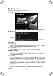
The LOGO Screen (Default) B. Motherboard Model BIOS Version Z68XP-UD4 E6 . . . . : BIOS Setup : XpressRecovery2 : Boot Menu : Qflash 05/13/2011-Z68-7A89WG0JC-00 Function Keys Function Keys Function Keys: : POST SCREEN Press the key to accept. For ... access Boot Menu again to change the first boot device setting as needed. : Q-FLASH Press the key to access the Q-Flash utility directly without entering BIOS Setup. After system restart, the device boot order will directly boot from the device configured in Boot Menu is effective for subsequent access to set...
The LOGO Screen (Default) B. Motherboard Model BIOS Version Z68XP-UD4 E6 . . . . : BIOS Setup : XpressRecovery2 : Boot Menu : Qflash 05/13/2011-Z68-7A89WG0JC-00 Function Keys Function Keys Function Keys: : POST SCREEN Press the key to accept. For ... access Boot Menu again to change the first boot device setting as needed. : Q-FLASH Press the key to access the Q-Flash utility directly without entering BIOS Setup. After system restart, the device boot order will directly boot from the device configured in Boot Menu is effective for subsequent access to set...

User Manual
Page 35
...Select Item F10: Save & Exit Setup Change CPU's Clock & Voltage F11: Save CMOS to BIOS F12: Load CMOS from BIOS BIOS Setup Program Function Keys Move the selection bar to select an item Execute command or enter the submenu... Main Menu: Exit the BIOS Setup program Submenus: Exit current submenu Increase the numeric value or make changes Decrease ... of the submenu. • If you do not find the settings you enter the BIOS Setup program, the Main Menu (as usual, select the Load Optimized Defaults item to set your system...
...Select Item F10: Save & Exit Setup Change CPU's Clock & Voltage F11: Save CMOS to BIOS F12: Load CMOS from BIOS BIOS Setup Program Function Keys Move the selection bar to select an item Execute command or enter the submenu... Main Menu: Exit the BIOS Setup program Submenus: Exit current submenu Increase the numeric value or make changes Decrease ... of the submenu. • If you do not find the settings you enter the BIOS Setup program, the Main Menu (as usual, select the Load Optimized Defaults item to set your system...
User Manual
Page 36
...to configure the system time and date, hard drive types, and the type of errors that stop the system boot, etc. Advanced BIOS Features Use this menu to configure the device boot order, advanced features available on the CPU, and the primary display adapter. Integrated ...peripheral devices, such as SATA, USB, integrated audio, and integrated LAN, etc. Power Management Setup Use this menu to the system and BIOS Setup. It allows you to restrict access to configure all the power-saving functions. PC Health Status Use this task.) Exit Without...
...to configure the system time and date, hard drive types, and the type of errors that stop the system boot, etc. Advanced BIOS Features Use this menu to configure the device boot order, advanced features available on the CPU, and the primary display adapter. Integrated ...peripheral devices, such as SATA, USB, integrated audio, and integrated LAN, etc. Power Management Setup Use this menu to the system and BIOS Setup. It allows you to restrict access to configure all the power-saving functions. PC Health Status Use this task.) Exit Without...
User Manual
Page 37
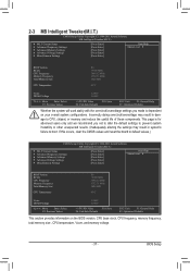
... } Miscellaneous Settings [Press Enter] [Press Enter] [Press Enter] [Press Enter] [Press Enter] Item Help Menu Level BIOS Version BCLK CPU Frequency Memory Frequency Total Memory Size CPU Temperature E6 99.80 MHz 3094.12 MHz 1332.71 MHz 1024 MB 45oC ... } Miscellaneous Settings [Press Enter] [Press Enter] [Press Enter] [Press Enter] [Press Enter] Item Help Menu Level BIOS Version BCLK CPU Frequency Memory Frequency Total Memory Size CPU Temperature E6 99.80 MHz 3094.12 MHz 1332.71 MHz 1024 MB 45oC ...
... } Miscellaneous Settings [Press Enter] [Press Enter] [Press Enter] [Press Enter] [Press Enter] Item Help Menu Level BIOS Version BCLK CPU Frequency Memory Frequency Total Memory Size CPU Temperature E6 99.80 MHz 3094.12 MHz 1332.71 MHz 1024 MB 45oC ... } Miscellaneous Settings [Press Enter] [Press Enter] [Press Enter] [Press Enter] [Press Enter] Item Help Menu Level BIOS Version BCLK CPU Frequency Memory Frequency Total Memory Size CPU Temperature E6 99.80 MHz 3094.12 MHz 1332.71 MHz 1024 MB 45oC ...
User Manual
Page 38
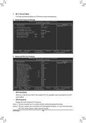
... present only if you to alter the clock ratio for the installed CPU. For more information about Intel CPUs' unique features, please visit Intel's website. BIOS Setup - 38 - M.I.T.
... present only if you to alter the clock ratio for the installed CPU. For more information about Intel CPUs' unique features, please visit Intel's website. BIOS Setup - 38 - M.I.T.


