
Manual
Page 1
...an SSD larger than 64 GB, the space beyond 64 GB can still be lost once you enable RAID mode. Then save changes and exit BIOS Setup. Installing a conventional SATA hard disk and a solid-state drive (SSD): Besides the conventional SATA disk, you have installed the operating ...Enter: Select F5: Previous Values +/-/PU/PD: Value F10: Save F6: Fail-Safe Defaults ESC: Exit F1: General Help F7: Optimized Defaults The BIOS Setup menus described here may differ from the exact settings for storing your motherboard. Installing the operating system and drivers to enable the Intel®...
...an SSD larger than 64 GB, the space beyond 64 GB can still be lost once you enable RAID mode. Then save changes and exit BIOS Setup. Installing a conventional SATA hard disk and a solid-state drive (SSD): Besides the conventional SATA disk, you have installed the operating ...Enter: Select F5: Previous Values +/-/PU/PD: Value F10: Save F6: Fail-Safe Defaults ESC: Exit F1: General Help F7: Optimized Defaults The BIOS Setup menus described here may differ from the exact settings for storing your motherboard. Installing the operating system and drivers to enable the Intel®...

Manual
Page 2
... enable the Intel Smart Response Technology: Step 1: After completing the steps above . 4. Installing the operating system and drivers to the SATA disk: After setting the BIOS, you can begin to install all motherboard drivers, including the Intel Rapid Storage Technology driver. Make sure the Intel Rapid Storage Technology driver version is...
... enable the Intel Smart Response Technology: Step 1: After completing the steps above . 4. Installing the operating system and drivers to the SATA disk: After setting the BIOS, you can begin to install all motherboard drivers, including the Intel Rapid Storage Technology driver. Make sure the Intel Rapid Storage Technology driver version is...
Manual
Page 3
... All rights reserved. For product-related information, check on our website at: http://www.gigabyte.com Identifying Your Motherboard Revision The revision number on your motherboard revision before updating motherboard BIOS, drivers, or when looking for technical information. For example, "REV: 1.0" means the .... The trademarks mentioned in this manual are legally registered to assist in any form or by GIGABYTE without GIGABYTE's prior written permission. No part of this product, GIGABYTE provides the following types of documentations: For quick set-up of the motherboard is ...
... All rights reserved. For product-related information, check on our website at: http://www.gigabyte.com Identifying Your Motherboard Revision The revision number on your motherboard revision before updating motherboard BIOS, drivers, or when looking for technical information. For example, "REV: 1.0" means the .... The trademarks mentioned in this manual are legally registered to assist in any form or by GIGABYTE without GIGABYTE's prior written permission. No part of this product, GIGABYTE provides the following types of documentations: For quick set-up of the motherboard is ...
Manual
Page 4
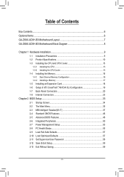
Table of Contents Box Contents...6 Optional Items...6 GA-Z68X-UD3H-B3 Motherboard Layout 7 GA-Z68X-UD3H-B3 Motherboard Block Diagram 8 Chapter 1 Hardware Installation 9 1-1 Installation Precautions 9 1-2 Product Specifications 10 1-3 Installing the CPU and CPU Cooler ... SLI Configuration 19 1-7 Back Panel Connectors 20 1-8 Internal Connectors 23 Chapter 2 BIOS Setup 33 2-1 Startup Screen 34 2-2 The Main Menu 35 2-3 MB Intelligent Tweaker(M.I.T 37 2-4 Standard CMOS Features 46 2-5 Advanced BIOS Features 48 2-6 Integrated Peripherals 50 2-7 Power Management Setup 53 2-8 PC Health ...
Table of Contents Box Contents...6 Optional Items...6 GA-Z68X-UD3H-B3 Motherboard Layout 7 GA-Z68X-UD3H-B3 Motherboard Block Diagram 8 Chapter 1 Hardware Installation 9 1-1 Installation Precautions 9 1-2 Product Specifications 10 1-3 Installing the CPU and CPU Cooler ... SLI Configuration 19 1-7 Back Panel Connectors 20 1-8 Internal Connectors 23 Chapter 2 BIOS Setup 33 2-1 Startup Screen 34 2-2 The Main Menu 35 2-3 MB Intelligent Tweaker(M.I.T 37 2-4 Standard CMOS Features 46 2-5 Advanced BIOS Features 48 2-6 Integrated Peripherals 50 2-7 Power Management Setup 53 2-8 PC Health ...

Manual
Page 5
... 62 3-4 Contact...63 3-5 System...63 3-6 Download Center 64 3-7 New Utilities...64 Chapter 4 Unique Features 65 4-1 Xpress Recovery2 65 4-2 BIOS Update Utilities 68 4-2-1 Updating the BIOS with the Q-Flash Utility 68 4-2-2 Updating the BIOS with the @BIOS Utility 71 4-3 EasyTune 6...72 4-4 Dynamic Energy Saver™ 2 73 4-5 Q-Share...75 4-6 Smart 6™ ...76 4-7 Auto Green...80 4-8 eXtreme...
... 62 3-4 Contact...63 3-5 System...63 3-6 Download Center 64 3-7 New Utilities...64 Chapter 4 Unique Features 65 4-1 Xpress Recovery2 65 4-2 BIOS Update Utilities 68 4-2-1 Updating the BIOS with the Q-Flash Utility 68 4-2-2 Updating the BIOS with the @BIOS Utility 71 4-3 EasyTune 6...72 4-4 Dynamic Energy Saver™ 2 73 4-5 Q-Share...75 4-6 Smart 6™ ...76 4-7 Auto Green...80 4-8 eXtreme...
Manual
Page 8
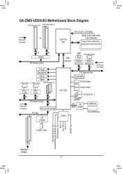
GA-Z68X-UD3H-B3 Motherboard Block Diagram 1 PCI Express x16 2 PCI Express x8 or PCIe CLK (100 MHz) LGA1155 CPU CPU CLK+/- (133 MHz) DDR3 2133/1866/1600/ 1333/... Bridge PCI Bus VIA VT6308 DMI Interface LAN 2 SATA 6Gb/s RJ45 Realtek RTL8111E x1 Marvell 88SE9172 x1 PCIe CLK (100 MHz) PCI Express Bus Dual BIOS 2 SATA 6Gb/s Intel® Z68 4 SATA 3Gb/s 12 USB 2.0/1.1 CODEC LPC iTE Bus IT8728 COM Port PS/2 KB/Mouse 2 IEEE 1394a Surround Speaker Out Center...
GA-Z68X-UD3H-B3 Motherboard Block Diagram 1 PCI Express x16 2 PCI Express x8 or PCIe CLK (100 MHz) LGA1155 CPU CPU CLK+/- (133 MHz) DDR3 2133/1866/1600/ 1333/... Bridge PCI Bus VIA VT6308 DMI Interface LAN 2 SATA 6Gb/s RJ45 Realtek RTL8111E x1 Marvell 88SE9172 x1 PCIe CLK (100 MHz) PCI Express Bus Dual BIOS 2 SATA 6Gb/s Intel® Z68 4 SATA 3Gb/s 12 USB 2.0/1.1 CODEC LPC iTE Bus IT8728 COM Port PS/2 KB/Mouse 2 IEEE 1394a Surround Speaker Out Center...
Manual
Page 12
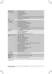
...Mbit flash ŠŠ Use of licensed AWARD BIOS ŠŠ Support for DualBIOS™ ŠŠ PnP 1.0a, DMI 2.0, SM BIOS 2.4, ACPI 1.0b Unique Features ŠŠ Support for @BIOS ŠŠ Support for Q-Flash ŠŠ Support for Xpress BIOS Rescue ŠŠ Support for Download Center &#...;Š Support for Microsoft® Windows 7/Vista/XP Form Factor ŠŠ ATX Form Factor; 30.5cm x 24.4cm * GIGABYTE reserves the right to make any changes to the product specifications and product-related information without prior notice. Hardware Installation - 12 -
...Mbit flash ŠŠ Use of licensed AWARD BIOS ŠŠ Support for DualBIOS™ ŠŠ PnP 1.0a, DMI 2.0, SM BIOS 2.4, ACPI 1.0b Unique Features ŠŠ Support for @BIOS ŠŠ Support for Q-Flash ŠŠ Support for Xpress BIOS Rescue ŠŠ Support for Download Center &#...;Š Support for Microsoft® Windows 7/Vista/XP Form Factor ŠŠ ATX Form Factor; 30.5cm x 24.4cm * GIGABYTE reserves the right to make any changes to the product specifications and product-related information without prior notice. Hardware Installation - 12 -
Manual
Page 16
... When enabling Dual Channel mode with two memory modules, we recommend that the motherboard supports the memory. It is installed, the BIOS will double the original memory bandwidth. After the memory is recommended that memory of the memory. DS/SS DDR3_3 - Hardware Installation... memory mode will automatically detect the specifications and capacity of the same capacity, brand, speed, and chips be used . (Go to GIGABYTE's website for optimum performance. 1-4 Installing the Memory Read the following guidelines before you begin to prevent hardware damage. •• Memory...
... When enabling Dual Channel mode with two memory modules, we recommend that the motherboard supports the memory. It is installed, the BIOS will double the original memory bandwidth. After the memory is recommended that memory of the memory. DS/SS DDR3_3 - Hardware Installation... memory mode will automatically detect the specifications and capacity of the same capacity, brand, speed, and chips be used . (Go to GIGABYTE's website for optimum performance. 1-4 Installing the Memory Read the following guidelines before you begin to prevent hardware damage. •• Memory...
Manual
Page 18
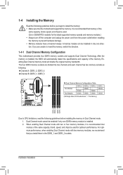
If necessary, go to BIOS Setup to make any required BIOS changes for your expansion card(s). 777 Install the driver provided with the slot, and press down on the top edge of the PCI Express slot ...
If necessary, go to BIOS Setup to make any required BIOS changes for your expansion card(s). 777 Install the driver provided with the slot, and press down on the top edge of the PCI Express slot ...
Manual
Page 21
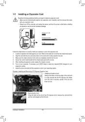
... operating system environment only, but the actual resolutions supported depend on configuring a RAID array. DisplayPort can support a maximum resolution of 2560x1600p but not during the BIOS Setup or POST process.
... operating system environment only, but the actual resolutions supported depend on configuring a RAID array. DisplayPort can support a maximum resolution of 2560x1600p but not during the BIOS Setup or POST process.

Manual
Page 25
... 1 GND 1 CPU_FAN 2 +12V /Speed Control 3 Sense 4 Speed Control SYS_FAN2 : 1 Pin No. Replace the battery when the battery voltage drops to keep the values (such as BIOS configurations, date, and time information) in damage to connect it is replaced with fan speed control design. When connecting a fan cable, be sure to the...
... 1 GND 1 CPU_FAN 2 +12V /Speed Control 3 Sense 4 Speed Control SYS_FAN2 : 1 Pin No. Replace the battery when the battery voltage drops to keep the values (such as BIOS configurations, date, and time information) in damage to connect it is replaced with fan speed control design. When connecting a fan cable, be sure to the...

Manual
Page 27
..., place a jumper cap on the two pins to temporarily short the two pins or use a metal object like a screwdriver to Chapter 2, "BIOS Setup," for BIOS configurations). - 27 - Failure to do so may cause damage to the motherboard. •• After system restart, go to...the power outlet before clearing the CMOS values. •• After clearing the CMOS values and before turning on configuring a RAID array. date information and BIOS configurations) and reset the CMOS values to Chapter 5, "Configuring SATA Hard Drive(s)," for a few seconds. Open: Normal Short: Clear CMOS Values •...
..., place a jumper cap on the two pins to temporarily short the two pins or use a metal object like a screwdriver to Chapter 2, "BIOS Setup," for BIOS configurations). - 27 - Failure to do so may cause damage to the motherboard. •• After system restart, go to...the power outlet before clearing the CMOS values. •• After clearing the CMOS values and before turning on configuring a RAID array. date information and BIOS configurations) and reset the CMOS values to Chapter 5, "Configuring SATA Hard Drive(s)," for a few seconds. Open: Normal Short: Clear CMOS Values •...

Manual
Page 28
... status indicator on the chassis that can detect if the chassis cover has been removed. The LED is off when the system is detected, the BIOS may differ by issuing a beep code. You may configure the way to turn off (S5). • PW (Power Switch, Red): Connects to ... the positive and negative pins before connecting the cables. RESRES+ CICI+ PWR+ PWR- When connecting your system using the power switch (refer to Chapter 2, "BIOS Setup," "Power Management Setup," for information about beep codes. • HD (Hard Drive Activity LED, Blue) Connects to the hard drive activity LED on ...
... status indicator on the chassis that can detect if the chassis cover has been removed. The LED is off when the system is detected, the BIOS may differ by issuing a beep code. You may configure the way to turn off (S5). • PW (Power Switch, Red): Connects to ... the positive and negative pins before connecting the cables. RESRES+ CICI+ PWR+ PWR- When connecting your system using the power switch (refer to Chapter 2, "BIOS Setup," "Power Management Setup," for information about beep codes. • HD (Hard Drive Activity LED, Blue) Connects to the hard drive activity LED on ...

Manual
Page 30
... Installation - 30 - Definition 1 VBUS 11 D2+ 2 SSRX1- 12 D2- 3 SSRX1+ 13 GND 4 GND 14 SSTX2+ 5 SSTX1- 15 SSTX2- 6 SSTX1+ 16 GND 7 GND 17 SSRX2+ DB_PORT BIOS 8 D1- 18 SSRX2- 9 D1+ 19 VBUS 10 NC 20 No Pin •• Do not plug the IEEE 1394 bracket (2x5-pin) cable into the...
... Installation - 30 - Definition 1 VBUS 11 D2+ 2 SSRX1- 12 D2- 3 SSRX1+ 13 GND 4 GND 14 SSTX2+ 5 SSTX1- 15 SSTX2- 6 SSTX1+ 16 GND 7 GND 17 SSRX2+ DB_PORT BIOS 8 D1- 18 SSRX2- 9 D1+ 19 VBUS 10 NC 20 No Pin •• Do not plug the IEEE 1394 bracket (2x5-pin) cable into the...

Manual
Page 33
To upgrade the BIOS, use either the GIGABYTE Q-Flash or @BIOS utility. •• Q-Flash allows the user to quickly and easily upgrade or back up BIOS without entering the operating system. •• @BIOS is a Windows-based utility that allows the user to modify basic system configuration ... the "Load Optimized Defaults" section in this chapter or introductions of the battery/clearing CMOS jumper in the CMOS on . Chapter 2 BIOS Setup BIOS (Basic Input and Output System) records hardware parameters of the system in Chapter 1 for the beep codes description. •• It...
To upgrade the BIOS, use either the GIGABYTE Q-Flash or @BIOS utility. •• Q-Flash allows the user to quickly and easily upgrade or back up BIOS without entering the operating system. •• @BIOS is a Windows-based utility that allows the user to modify basic system configuration ... the "Load Optimized Defaults" section in this chapter or introductions of the battery/clearing CMOS jumper in the CMOS on . Chapter 2 BIOS Setup BIOS (Basic Input and Output System) records hardware parameters of the system in Chapter 1 for the beep codes description. •• It...
Manual
Page 34
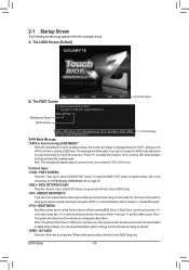
... boot device, then press to Chapter 4, "Xpress Recovery2." : BOOT MENU Boot Menu allows you the SATA controller is effective for the SATA connectors. Motherboard Model BIOS Version Z68X-UD3H-B3 F1r . . . . When the motherboard is found running at next boot if you want to change the first boot device setting as needed. : Q-FLASH Press...
... boot device, then press to Chapter 4, "Xpress Recovery2." : BOOT MENU Boot Menu allows you the SATA controller is effective for the SATA connectors. Motherboard Model BIOS Version Z68X-UD3H-B3 F1r . . . . When the motherboard is found running at next boot if you want to change the first boot device setting as needed. : Q-FLASH Press...

Manual
Page 35
... Save & Exit Setup Exit Without Saving ESC: Quit F8: Q-Flash Select Item F10: Save & Exit Setup Change CPU's Clock & Voltage F11: Save CMOS to BIOS F12: Load CMOS from BIOS BIOS Setup Program Function Keys Move the selection bar to select an item Execute command or enter the submenu Main Menu: Exit the... is in the Item Help block on the right side of the submenu. •• If you do not find the settings you enter the BIOS Setup program, the Main Menu (as usual, select the Load Optimized Defaults item to set your system to its defaults. •• The...
... Save & Exit Setup Exit Without Saving ESC: Quit F8: Q-Flash Select Item F10: Save & Exit Setup Change CPU's Clock & Voltage F11: Save CMOS to BIOS F12: Load CMOS from BIOS BIOS Setup Program Function Keys Move the selection bar to select an item Execute command or enter the submenu Main Menu: Exit the... is in the Item Help block on the right side of the submenu. •• If you do not find the settings you enter the BIOS Setup program, the Main Menu (as usual, select the Load Optimized Defaults item to set your system to its defaults. •• The...

Manual
Page 36
... but not to make changes in effect. First enter the profile name (to erase the default profile name, use this function to load the BIOS settings from BIOS If your CPU, memory, etc. Standard CMOS Features Use this menu to configure the system time and date, hard drive types, ...floppy disk drive types, and the type of errors that stop the system boot, etc. Advanced BIOS Features Use this menu to configure the device boot order, advanced features available on the CPU, and the primary display adapter. Integrated Peripherals ...
... but not to make changes in effect. First enter the profile name (to erase the default profile name, use this function to load the BIOS settings from BIOS If your CPU, memory, etc. Standard CMOS Features Use this menu to configure the system time and date, hard drive types, ...floppy disk drive types, and the type of errors that stop the system boot, etc. Advanced BIOS Features Use this menu to configure the device boot order, advanced features available on the CPU, and the primary display adapter. Integrated Peripherals ...

Manual
Page 37
... } Miscellaneous Settings [Press Enter] [Press Enter] [Press Enter] [Press Enter] [Press Enter] Item Help Menu Level BIOS Version BCLK CPU Frequency Memory Frequency Total Memory Size F1r 99.80 MHz 3193.86 MHz 1330.65 MHz 1024 MB CPU Temperature 30.0... } Miscellaneous Settings [Press Enter] [Press Enter] [Press Enter] [Press Enter] [Press Enter] Item Help Menu Level BIOS Version BCLK CPU Frequency Memory Frequency Total Memory Size F1r 99.80 MHz 3193.86 MHz 1330.65 MHz 1024 MB CPU Temperature 30.0...
... } Miscellaneous Settings [Press Enter] [Press Enter] [Press Enter] [Press Enter] [Press Enter] Item Help Menu Level BIOS Version BCLK CPU Frequency Memory Frequency Total Memory Size F1r 99.80 MHz 3193.86 MHz 1330.65 MHz 1024 MB CPU Temperature 30.0... } Miscellaneous Settings [Press Enter] [Press Enter] [Press Enter] [Press Enter] [Press Enter] Item Help Menu Level BIOS Version BCLK CPU Frequency Memory Frequency Total Memory Size F1r 99.80 MHz 3193.86 MHz 1330.65 MHz 1024 MB CPU Temperature 30.0...

Manual
Page 38
... is present only when you to alter the clock ratio for the installed CPU. Current Status This screen provides information on the CPU being installed. BIOS Setup - 38 - CPU Frequency Displays the current operating CPU frequency. (Note 1) This item is present only when you install a memory module that supports this feature...
... is present only when you to alter the clock ratio for the installed CPU. Current Status This screen provides information on the CPU being installed. BIOS Setup - 38 - CPU Frequency Displays the current operating CPU frequency. (Note 1) This item is present only when you install a memory module that supports this feature...


