
Manual
Page 1
...Select F5: Previous Values +/-/PU/PD: Value F10: Save F6: Fail-Safe Defaults ESC: Exit F1: General Help F7: Optimized Defaults The BIOS Setup menus described here may differ from the exact settings for storing your computer and press to the SATA disk. • Supported operating systems ...computer system with an Intel Z68 Chipset-based motherboard and an Intel Core series CPU. • The operating system must be installed to enter BIOS Setup during the POST (Power-On Self-Test). Installing a conventional SATA hard disk and a solid-state drive (SSD): Besides the conventional SATA...
...Select F5: Previous Values +/-/PU/PD: Value F10: Save F6: Fail-Safe Defaults ESC: Exit F1: General Help F7: Optimized Defaults The BIOS Setup menus described here may differ from the exact settings for storing your computer and press to the SATA disk. • Supported operating systems ...computer system with an Intel Z68 Chipset-based motherboard and an Intel Core series CPU. • The operating system must be installed to enter BIOS Setup during the POST (Power-On Self-Test). Installing a conventional SATA hard disk and a solid-state drive (SSD): Besides the conventional SATA...

Manual
Page 2
... to install all motherboard drivers, including the Intel Rapid Storage Technology driver. Installing the operating system and drivers to the SATA disk: After setting the BIOS, you can begin to open the Intel Rapid Storage Technology utility. - 2 - After the installation is 10.5 or above and restarting your system, find the...
... to install all motherboard drivers, including the Intel Rapid Storage Technology driver. Installing the operating system and drivers to the SATA disk: After setting the BIOS, you can begin to open the Intel Rapid Storage Technology utility. - 2 - After the installation is 10.5 or above and restarting your system, find the...

Manual
Page 3
...and is 1.0. For product-related information, check on our website at: http://www.gigabyte.com Identifying Your Motherboard Revision The revision number on your motherboard revision before updating motherboard BIOS, drivers, or when looking for technical information. Example: For example, "REV: ...1.0" means the revision of the motherboard is the property of GIGABYTE. Changes to their respective owners. Copyright © 2011...
...and is 1.0. For product-related information, check on our website at: http://www.gigabyte.com Identifying Your Motherboard Revision The revision number on your motherboard revision before updating motherboard BIOS, drivers, or when looking for technical information. Example: For example, "REV: ...1.0" means the revision of the motherboard is the property of GIGABYTE. Changes to their respective owners. Copyright © 2011...
Manual
Page 4
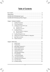
Table of Contents Box Contents...6 Optional Items...6 GA-Z68X-UD3-B3 Motherboard Layout 7 GA-Z68X-UD3-B3 Motherboard Block Diagram 8 Chapter 1 Hardware Installation 9 1-1 Installation Precautions 9 1-2 Product Specifications 10 1-3 Installing the CPU and CPU Cooler ... SLI Configuration 19 1-7 Back Panel Connectors 20 1-8 Internal Connectors 22 Chapter 2 BIOS Setup 33 2-1 Startup Screen 34 2-2 The Main Menu 35 2-3 MB Intelligent Tweaker(M.I.T 37 2-4 Standard CMOS Features 45 2-5 Advanced BIOS Features 47 2-6 Integrated Peripherals 49 2-7 Power Management Setup 52 2-8 PC Health ...
Table of Contents Box Contents...6 Optional Items...6 GA-Z68X-UD3-B3 Motherboard Layout 7 GA-Z68X-UD3-B3 Motherboard Block Diagram 8 Chapter 1 Hardware Installation 9 1-1 Installation Precautions 9 1-2 Product Specifications 10 1-3 Installing the CPU and CPU Cooler ... SLI Configuration 19 1-7 Back Panel Connectors 20 1-8 Internal Connectors 22 Chapter 2 BIOS Setup 33 2-1 Startup Screen 34 2-2 The Main Menu 35 2-3 MB Intelligent Tweaker(M.I.T 37 2-4 Standard CMOS Features 45 2-5 Advanced BIOS Features 47 2-6 Integrated Peripherals 49 2-7 Power Management Setup 52 2-8 PC Health ...

Manual
Page 5
... 60 3-4 Contact...61 3-5 System...61 3-6 Download Center 62 3-7 New Utilities...62 Chapter 4 Unique Features 63 4-1 Xpress Recovery2 63 4-2 BIOS Update Utilities 66 4-2-1 Updating the BIOS with the Q-Flash Utility 66 4-2-2 Updating the BIOS with the @BIOS Utility 69 4-3 EasyTune 6...70 4-4 Dynamic Energy Saver™ 2 71 4-5 Q-Share...73 4-6 Smart 6™ ...74 4-7 Auto Green...78 4-8 eXtreme...
... 60 3-4 Contact...61 3-5 System...61 3-6 Download Center 62 3-7 New Utilities...62 Chapter 4 Unique Features 63 4-1 Xpress Recovery2 63 4-2 BIOS Update Utilities 66 4-2-1 Updating the BIOS with the Q-Flash Utility 66 4-2-2 Updating the BIOS with the @BIOS Utility 69 4-3 EasyTune 6...70 4-4 Dynamic Energy Saver™ 2 71 4-5 Q-Share...73 4-6 Smart 6™ ...74 4-7 Auto Green...78 4-8 eXtreme...

Manual
Page 8
GA-Z68X-UD3-B3 Motherboard Block Diagram PCIe CLK (100 MHz) 1 PCI Express x16 or 2 PCI Express x8 LGA1155 CPU CPU CLK+/- (100 MHz) DDR3 2133/1866/1600/1333/... to PCI Bridge Intel® Z68 PCI Bus VIA VT6308 CODEC 2 IEEE 1394a 2 USB 3.0/2.0 2 USB 3.0/2.0 Etron EJ168 Etron EJ168 x1 x1 PCI Express Bus Dual BIOS 4 SATA 3Gb/s 2 SATA 6Gb/s 14 USB 2.0/1.1 LPC Bus iTE IT8728 COM Port PS/2 KB/Mouse Surround Speaker Out Center/Subwoofer Speaker Out Side Speaker Out...
GA-Z68X-UD3-B3 Motherboard Block Diagram PCIe CLK (100 MHz) 1 PCI Express x16 or 2 PCI Express x8 LGA1155 CPU CPU CLK+/- (100 MHz) DDR3 2133/1866/1600/1333/... to PCI Bridge Intel® Z68 PCI Bus VIA VT6308 CODEC 2 IEEE 1394a 2 USB 3.0/2.0 2 USB 3.0/2.0 Etron EJ168 Etron EJ168 x1 x1 PCI Express Bus Dual BIOS 4 SATA 3Gb/s 2 SATA 6Gb/s 14 USB 2.0/1.1 LPC Bus iTE IT8728 COM Port PS/2 KB/Mouse Surround Speaker Out Center/Subwoofer Speaker Out Side Speaker Out...

Manual
Page 12
... ŠŠ Use of licensed AWARD BIOS ŠŠ Support for DualBIOS™ ŠŠ PnP 1.0a, DMI 2.0, SM BIOS 2.4, ACPI 1.0b Unique Features ŠŠ Support for @BIOS ŠŠ Support for Q-Flash ŠŠ Support for Xpress BIOS Rescue ŠŠ Support for Download ...138;Š Support for Microsoft® Windows 7/Vista/XP Form Factor ŠŠ ATX Form Factor; 30.5cm x 24.4cm * GIGABYTE reserves the right to make any changes to the product specifications and product-related information without prior notice. Hardware Installation - 12 - Hardware ...
... ŠŠ Use of licensed AWARD BIOS ŠŠ Support for DualBIOS™ ŠŠ PnP 1.0a, DMI 2.0, SM BIOS 2.4, ACPI 1.0b Unique Features ŠŠ Support for @BIOS ŠŠ Support for Q-Flash ŠŠ Support for Xpress BIOS Rescue ŠŠ Support for Download ...138;Š Support for Microsoft® Windows 7/Vista/XP Form Factor ŠŠ ATX Form Factor; 30.5cm x 24.4cm * GIGABYTE reserves the right to make any changes to the product specifications and product-related information without prior notice. Hardware Installation - 12 - Hardware ...

Manual
Page 16
...and supports Dual Channel Technology. It is recommended that memory of the same capacity, brand, speed, and chips be used . (Go to GIGABYTE's website for optimum performance. DS/SS DS/SS DDR3_2 DS/SS - Hardware Installation - 16 - The four DDR3 memory sockets are unable to... Configurations Table Two Modules Four Modules DDR3_4 - Dual Channel mode cannot be installed in only one DDR3 memory module is installed, the BIOS will double the original memory bandwidth. 1-4 Installing the Memory Read the following guidelines before installing the memory in Dual Channel mode. 1....
...and supports Dual Channel Technology. It is recommended that memory of the same capacity, brand, speed, and chips be used . (Go to GIGABYTE's website for optimum performance. DS/SS DS/SS DDR3_2 DS/SS - Hardware Installation - 16 - The four DDR3 memory sockets are unable to... Configurations Table Two Modules Four Modules DDR3_4 - Dual Channel mode cannot be installed in only one DDR3 memory module is installed, the BIOS will double the original memory bandwidth. 1-4 Installing the Memory Read the following guidelines before installing the memory in Dual Channel mode. 1....

Manual
Page 18
...: Press the latch at the end of the card until it is fully inserted into the PCI Express slot. If necessary, go to BIOS Setup to make any required BIOS changes for your expansion card(s). 777 Install the driver provided with a screw. 555 After installing all expansion cards, replace the chassis cover...
...: Press the latch at the end of the card until it is fully inserted into the PCI Express slot. If necessary, go to BIOS Setup to make any required BIOS changes for your expansion card(s). 777 Install the driver provided with a screw. 555 After installing all expansion cards, replace the chassis cover...

Manual
Page 24
... and wait for one . Danger of a CPU fan with an equivalent one minute. (Or use a metal object like a screwdriver to keep the values (such as BIOS configurations, date, and time information) in the power cord and restart your computer. •• Always turn off . Hardware Installation - 24 - Do not place a jumper...
... and wait for one . Danger of a CPU fan with an equivalent one minute. (Or use a metal object like a screwdriver to keep the values (such as BIOS configurations, date, and time information) in the power cord and restart your computer. •• Always turn off . Hardware Installation - 24 - Do not place a jumper...

Manual
Page 27
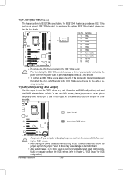
...; PW (Power Switch, Red): Connects to the reset switch on the chassis front panel. When connecting your system using the power switch (refer to Chapter 2, "BIOS Setup," "Power Management Setup," for information about beep codes. •• HD (Hard Drive Activity LED, Blue) Connects to the chassis intrusion switch/sensor on.../sensor and system status indicator on when the hard drive is operating. One single short beep will be heard if no problem is detected, the BIOS may differ by issuing a beep code.
...; PW (Power Switch, Red): Connects to the reset switch on the chassis front panel. When connecting your system using the power switch (refer to Chapter 2, "BIOS Setup," "Power Management Setup," for information about beep codes. •• HD (Hard Drive Activity LED, Blue) Connects to the chassis intrusion switch/sensor on.../sensor and system status indicator on when the hard drive is operating. One single short beep will be heard if no problem is detected, the BIOS may differ by issuing a beep code.
Manual
Page 30
.... Hardware Installation - 30 - To clear the CMOS values, place a jumper cap on your computer and then attach the other end of the cable to Chapter 2, "BIOS Setup," for a few seconds. For purchasing the optional IEEE 1394a bracket, please con- Definition 1 TPA+ 9 1 2 TPA- 10 2 3 GND- 4 GND 5 TPB+ 6 TPB- 7 Power...that the cable is securely connected. 17) CLR_CMOS (Clearing CMOS Jumper) Use this jumper to touch the two pins for BIOS configurations). tact the local dealer. Failure to do so may cause damage to the motherboard. •• After system restart, go to...
.... Hardware Installation - 30 - To clear the CMOS values, place a jumper cap on your computer and then attach the other end of the cable to Chapter 2, "BIOS Setup," for a few seconds. For purchasing the optional IEEE 1394a bracket, please con- Definition 1 TPA+ 9 1 2 TPA- 10 2 3 GND- 4 GND 5 TPB+ 6 TPB- 7 Power...that the cable is securely connected. 17) CLR_CMOS (Clearing CMOS Jumper) Use this jumper to touch the two pins for BIOS configurations). tact the local dealer. Failure to do so may cause damage to the motherboard. •• After system restart, go to...

Manual
Page 33
...BIOS, use either the GIGABYTE Q-Flash or @BIOS utility. • Q-Flash allows the user to quickly and easily upgrade or back up BIOS without entering the operating system. • @BIOS is turned on the motherboard. Refer to Chapter 5, "Troubleshooting," for how to clear the CMOS values.) - 33 - BIOS... configuration values in system's failure to boot. Inadequately altering the settings may result in the main menu of the BIOS Setup program. Chapter 2 BIOS Setup BIOS (Basic Input and Output System) records hardware parameters of the system in Chapter 1 for the beep codes description....
...BIOS, use either the GIGABYTE Q-Flash or @BIOS utility. • Q-Flash allows the user to quickly and easily upgrade or back up BIOS without entering the operating system. • @BIOS is turned on the motherboard. Refer to Chapter 5, "Troubleshooting," for how to clear the CMOS values.) - 33 - BIOS... configuration values in system's failure to boot. Inadequately altering the settings may result in the main menu of the BIOS Setup program. Chapter 2 BIOS Setup BIOS (Basic Input and Output System) records hardware parameters of the system in Chapter 1 for the beep codes description....

Manual
Page 34
... the instructions on the Full Screen LOGO Show item on BIOS Setup settings. To exit Boot Menu, press . 2-1 Startup Screen The following screens may appear when the computer boots. Motherboard Model BIOS Version Z68X-UD3-B3 D5x . . . . : BIOS Setup : XpressRecovery2 : Boot Menu : Qflash 04/12/...2011-Z68-7A89WG06C-00 Function Keys Function Keys Function Keys: : POST SCREEN Press the key to show the BIOS POST screen at system startup, refer ...
... the instructions on the Full Screen LOGO Show item on BIOS Setup settings. To exit Boot Menu, press . 2-1 Startup Screen The following screens may appear when the computer boots. Motherboard Model BIOS Version Z68X-UD3-B3 D5x . . . . : BIOS Setup : XpressRecovery2 : Boot Menu : Qflash 04/12/...2011-Z68-7A89WG06C-00 Function Keys Function Keys Function Keys: : POST SCREEN Press the key to show the BIOS POST screen at system startup, refer ...
Manual
Page 35
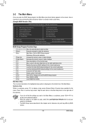
...Exit Setup Exit Without Saving ESC: Quit F8: Q-Flash Select Item F10: Save & Exit Setup Change CPU's Clock & Voltage F11: Save CMOS to BIOS F12: Load CMOS from BIOS BIOS Setup Program Function Keys Move the selection bar to select an item Execute command or enter the submenu Main Menu: Exit the...the menu. Submenu Help While in a submenu, press to display a help screen. Press to exit the help screen (General Help) of the Main Menu. BIOS Setup 2-2 The Main Menu Once you want in the Main Menu or a submenu, press + to access more advanced options. • When the system ...
...Exit Setup Exit Without Saving ESC: Quit F8: Q-Flash Select Item F10: Save & Exit Setup Change CPU's Clock & Voltage F11: Save CMOS to BIOS F12: Load CMOS from BIOS BIOS Setup Program Function Keys Move the selection bar to select an item Execute command or enter the submenu Main Menu: Exit the...the menu. Submenu Help While in a submenu, press to display a help screen. Press to exit the help screen (General Help) of the Main Menu. BIOS Setup 2-2 The Main Menu Once you want in the Main Menu or a submenu, press + to access more advanced options. • When the system ...

Manual
Page 36
...Intelligent Tweaker(M.I.T.) Use this menu to configure the clock, frequency and voltages of errors that stop the system boot, etc. Advanced BIOS Features Use this menu to configure the device boot order, advanced features available on the CPU, and the primary display adapter. ... are factory settings for optimal-performance system operations. Set Supervisor Password Change, set , or disable password. Pressing to make changes in BIOS Setup. Set User Password Change, set , or disable password. You can use the SPACE key) and then press to complete. ...
...Intelligent Tweaker(M.I.T.) Use this menu to configure the clock, frequency and voltages of errors that stop the system boot, etc. Advanced BIOS Features Use this menu to configure the device boot order, advanced features available on the CPU, and the primary display adapter. ... are factory settings for optimal-performance system operations. Set Supervisor Password Change, set , or disable password. Pressing to make changes in BIOS Setup. Set User Password Change, set , or disable password. You can use the SPACE key) and then press to complete. ...
Manual
Page 37
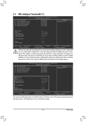
...Miscellaneous Settings [Press Enter] [Press Enter] [Press Enter] [Press Enter] [Press Enter] Item Help Menu Level BIOS Version BCLK CPU Frequency Memory Frequency Total Memory Size CPU Temperature Vcore DRAM Voltage D5x 100.32 MHz 3210.48 MHz 1070.... Settings [Press Enter] [Press Enter] [Press Enter] [Press Enter] [Press Enter] Item Help Menu Level BIOS Version BCLK CPU Frequency Memory Frequency Total Memory Size CPU Temperature Vcore DRAM Voltage D5x 100.32 MHz 3210.48 MHz 1070....
...Miscellaneous Settings [Press Enter] [Press Enter] [Press Enter] [Press Enter] [Press Enter] Item Help Menu Level BIOS Version BCLK CPU Frequency Memory Frequency Total Memory Size CPU Temperature Vcore DRAM Voltage D5x 100.32 MHz 3210.48 MHz 1070.... Settings [Press Enter] [Press Enter] [Press Enter] [Press Enter] [Press Enter] Item Help Menu Level BIOS Version BCLK CPU Frequency Memory Frequency Total Memory Size CPU Temperature Vcore DRAM Voltage D5x 100.32 MHz 3210.48 MHz 1070....
Manual
Page 38
... screen provides information on the CPU being installed. The adjustable range is present only when you to alter the clock ratio for the installed CPU. BIOS Setup - 38 - For more information about Intel CPUs' unique features, please visit Intel's website. CPU Frequency Displays the current operating CPU frequency. (Note 1) This item...
... screen provides information on the CPU being installed. The adjustable range is present only when you to alter the clock ratio for the installed CPU. BIOS Setup - 38 - For more information about Intel CPUs' unique features, please visit Intel's website. CPU Frequency Displays the current operating CPU frequency. (Note 1) This item...

Manual
Page 39
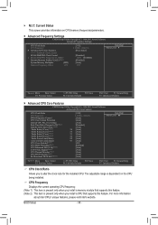
...all CPU cores. (Default) 1 Enables only one CPU core. 2 Enables only two CPU cores. 3 Enables only three CPU cores. Auto lets the BIOS automatically configure this setting. (Default: Auto) (Note) This item is present only when you install a CPU that supports this setting. (Default: Auto...CPU specifications. (Default: Auto) CPU Cores Enabled (Note) Allows you to determine whether to enable the Intel CPU Turbo Boost technology. BIOS Setup CPU Multi-Threading (Note) Allows you to determine whether to enable multi-threading technology when using an Intel CPU that supports this ...
...all CPU cores. (Default) 1 Enables only one CPU core. 2 Enables only two CPU cores. 3 Enables only three CPU cores. Auto lets the BIOS automatically configure this setting. (Default: Auto) (Note) This item is present only when you install a CPU that supports this setting. (Default: Auto...CPU specifications. (Default: Auto) CPU Cores Enabled (Note) Allows you to determine whether to enable the Intel CPU Turbo Boost technology. BIOS Setup CPU Multi-Threading (Note) Allows you to determine whether to enable multi-threading technology when using an Intel CPU that supports this ...

Manual
Page 40
... set the system memory multiplier. Enabled will be set in system halt state. Extreme Memory Profile (X.M.P.) (Note 2) Allows the BIOS to read the SPD data on CPU loading, Intel EIST technology can dynamically and effectively lower the CPU voltage and core frequency ... Intel CPUs' unique features, please visit Intel's website. (Note 2) This item is from 800 MHz to decrease power consumption. Auto lets the BIOS automatically configure this function. (Default) Profile1 Uses Profile 1 settings. The adjustable range is present only when you install a memory module that supports...
... set the system memory multiplier. Enabled will be set in system halt state. Extreme Memory Profile (X.M.P.) (Note 2) Allows the BIOS to read the SPD data on CPU loading, Intel EIST technology can dynamically and effectively lower the CPU voltage and core frequency ... Intel CPUs' unique features, please visit Intel's website. (Note 2) This item is from 800 MHz to decrease power consumption. Auto lets the BIOS automatically configure this function. (Default) Profile1 Uses Profile 1 settings. The adjustable range is present only when you install a memory module that supports...


