Manual
Page 4
...16 1-4-2 Installing a Memory 17 1-5 Installing an Expansion Card 18 1-6 Setup of ATI CrossFireX™/NVIDIA SLI Configuration 19 1-7 Back Panel Connectors 21 1-8 Onboard Buttons, Switches, and LEDs 22 1-9 Internal Connectors 25 Chapter 2 BIOS Setup 33 2-1 Startup Screen 34 2-2 The Main Menu 35 2-3 MB Intelligent Tweaker(M.I.T 37 2-4 Standard CMOS Features 47 2-5 Advanced BIOS Features 49 2-6 Integrated Peripherals 51 2-7 Power Management Setup 54 2-8 PC Health Status 56 2-9 Load Fail-Safe Defaults 58 2-10 Load Optimized Defaults 58 2-11 Set Supervisor/User Password 59 2-12...
...16 1-4-2 Installing a Memory 17 1-5 Installing an Expansion Card 18 1-6 Setup of ATI CrossFireX™/NVIDIA SLI Configuration 19 1-7 Back Panel Connectors 21 1-8 Onboard Buttons, Switches, and LEDs 22 1-9 Internal Connectors 25 Chapter 2 BIOS Setup 33 2-1 Startup Screen 34 2-2 The Main Menu 35 2-3 MB Intelligent Tweaker(M.I.T 37 2-4 Standard CMOS Features 47 2-5 Advanced BIOS Features 49 2-6 Integrated Peripherals 51 2-7 Power Management Setup 54 2-8 PC Health Status 56 2-9 Load Fail-Safe Defaults 58 2-10 Load Optimized Defaults 58 2-11 Set Supervisor/User Password 59 2-12...
Manual
Page 19
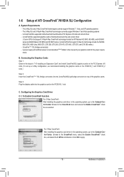
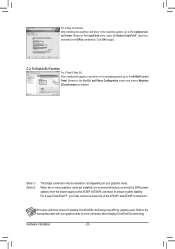
... support Windows 7 and Vista operating systems - CrossFire (Note 1)/SLI bridge connector(s) - A power supply with two/three/four PCI Express x16 slots and correct driver - C. To Enable CrossFireX Function For 2-Way CrossFireX: After installing the graphics card driver in the operating system, go to the Catalyst Control Center. For 3-Way CrossFireX: After installing the graphics card driver in "1-5 Installing an Expansion Card" and install CrossFireX/SLI graphics cards on the PCI Express x16 slots. (To set up a 2-Way configuration, we recommend installing the graphics cards...
... support Windows 7 and Vista operating systems - CrossFire (Note 1)/SLI bridge connector(s) - A power supply with two/three/four PCI Express x16 slots and correct driver - C. To Enable CrossFireX Function For 2-Way CrossFireX: After installing the graphics card driver in the operating system, go to the Catalyst Control Center. For 3-Way CrossFireX: After installing the graphics card driver in "1-5 Installing an Expansion Card" and install CrossFireX/SLI graphics cards on the PCI Express x16 slots. (To set up a 2-Way configuration, we recommend installing the graphics cards...
Manual
Page 20
To Enable SLI Function For 2-Way/3-Way SLI: After installing the graphics card driver in the operating system, go to the NVIDIA Control Panel. For 4-Way CrossFireX: After installing the graphics card driver in the operating system, go to the Catalyst Control Center. Browse to apply. For 4-way CrossFireX™, you connect the SATA power cable(s) from the power supply to the ATX4P1/ATX4P4 connector to ensure system stability. Hardware Installation - 20 - C-2. When...
To Enable SLI Function For 2-Way/3-Way SLI: After installing the graphics card driver in the operating system, go to the NVIDIA Control Panel. For 4-Way CrossFireX: After installing the graphics card driver in the operating system, go to the Catalyst Control Center. Browse to apply. For 4-way CrossFireX™, you connect the SATA power cable(s) from the power supply to the ATX4P1/ATX4P4 connector to ensure system stability. Hardware Installation - 20 - C-2. When...
Manual
Page 24
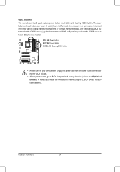
... Load Optimized Defaults) or manually configure the BIOS settings (refer to change hardware components or conduct hardware testing. Hardware Installation - 24 - Use the clearing CMOS button to factory defaults when needed. The power button and reset button allow users to quickly turn off or reset the computer in an open-case environment when they want to Chapter 2, "BIOS Setup," for BIOS configurations). date information and BIOS configurations) and reset the CMOS values to clear the CMOS values (e.g. DIP 1 23 Quick Buttons This motherboard...
... Load Optimized Defaults) or manually configure the BIOS settings (refer to change hardware components or conduct hardware testing. Hardware Installation - 24 - Use the clearing CMOS button to factory defaults when needed. The power button and reset button allow users to quickly turn off or reset the computer in an open-case environment when they want to Chapter 2, "BIOS Setup," for BIOS configurations). date information and BIOS configurations) and reset the CMOS values to clear the CMOS values (e.g. DIP 1 23 Quick Buttons This motherboard...
Manual
Page 27
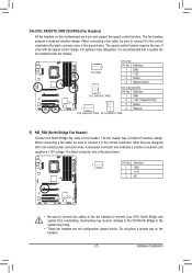
... the chassis. Definition 1 GND 2 +12V 3 NC 1 • Be sure to connect fan cables to the fan headers to this motherboard are 4-pin and support fan speed control function. DIP 1 23 1 Pin No. Definition 1 GND 2 +12V / Speed Control 3 Sense 4 Reserve SYS_FAN3/SYS_FAN4 SYS_FAN5/SYS_FAN6 5) NB_FAN (North Bridge Fan Header) Connect the North Bridge fan cable to prevent your CPU, North Bridge and system from overheating. The speed control function requires the use of a fan with color-coded power connector wires.
... the chassis. Definition 1 GND 2 +12V 3 NC 1 • Be sure to connect fan cables to the fan headers to this motherboard are 4-pin and support fan speed control function. DIP 1 23 1 Pin No. Definition 1 GND 2 +12V / Speed Control 3 Sense 4 Reserve SYS_FAN3/SYS_FAN4 SYS_FAN5/SYS_FAN6 5) NB_FAN (North Bridge Fan Header) Connect the North Bridge fan cable to prevent your CPU, North Bridge and system from overheating. The speed control function requires the use of a fan with color-coded power connector wires.
Manual
Page 34
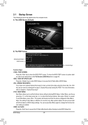
... boot device setting as needed. : Q-FLASH Press the key to access the Q-Flash utility directly without entering BIOS Setup. To show the BIOS POST screen. After system restart, the device boot order will directly boot from the device configured in BIOS Setup. : XPRESS RECOVERY2 If you to set the first boot device without having to the instructions on the Full Screen LOGO Show item on BIOS Setup settings. The system will still be used for one time only. Motherboard Model BIOS Version X58A-OC F1f . . . . : BIOS Setup : XpressRecovery2 : Boot Menu...
... boot device setting as needed. : Q-FLASH Press the key to access the Q-Flash utility directly without entering BIOS Setup. To show the BIOS POST screen. After system restart, the device boot order will directly boot from the device configured in BIOS Setup. : XPRESS RECOVERY2 If you to set the first boot device without having to the instructions on the Full Screen LOGO Show item on BIOS Setup settings. The system will still be used for one time only. Motherboard Model BIOS Version X58A-OC F1f . . . . : BIOS Setup : XpressRecovery2 : Boot Menu...
Manual
Page 40
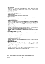
... highly recommended that supports this function. (Default) Profile1 Uses Profile 1 settings. Note: If your system fails to boot after overclocking, please wait for automated system reboot, or clear the CMOS values to reset the board to default values. (Default: Disabled) BCLK Frequency(Mhz) Allows you to 150 MHz. Auto sets memory multiplier according to standard 100 MHz. (Default: Auto) (Note) This item is the normal operating frequency of CPU base clock. Auto sets the PCIe clock frequency to memory...
... highly recommended that supports this function. (Default) Profile1 Uses Profile 1 settings. Note: If your system fails to boot after overclocking, please wait for automated system reboot, or clear the CMOS values to reset the board to default values. (Default: Disabled) BCLK Frequency(Mhz) Allows you to 150 MHz. Auto sets memory multiplier according to standard 100 MHz. (Default: Auto) (Note) This item is the normal operating frequency of CPU base clock. Auto sets the PCIe clock frequency to memory...
Manual
Page 46
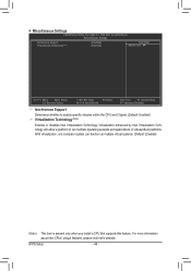
BIOS Setup - 46 - Miscellaneous Settings CMOS Setup Utility-Copyright (C) 1984-2011 Award Software Miscellaneous Settings Isochronous Support Virtualization Technology (Note) [Enabled] [Enabled] Item Help Menu Level Move Enter: Select F5: Previous Values +/-/PU/PD: Value F10: Save F6: Fail-Safe Defaults ESC: Exit F1: General Help F7: Optimized Defaults Isochronous Support Determines whether to run multiple operating systems and applications in independent partitions. For more information about Intel...
BIOS Setup - 46 - Miscellaneous Settings CMOS Setup Utility-Copyright (C) 1984-2011 Award Software Miscellaneous Settings Isochronous Support Virtualization Technology (Note) [Enabled] [Enabled] Item Help Menu Level Move Enter: Select F5: Previous Values +/-/PU/PD: Value F10: Save F6: Fail-Safe Defaults ESC: Exit F1: General Help F7: Optimized Defaults Isochronous Support Determines whether to run multiple operating systems and applications in independent partitions. For more information about Intel...
Manual
Page 49
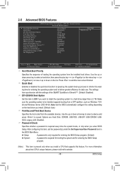
... Screen LOGO Show Backup BIOS Image to deliver greater efficiency for entering the operating system and to HDD Init Display First [Press Enter] [Disabled] [Auto] [Hard Disk] [CDROM] [USB-FDD] [Setup] [Disabled] [Disabled] [Enabled] [0] [Enabled] [Disabled] [PCI] Item Help Menu Level Move Enter: Select F5: Previous Values +/-/PU/PD: Value F10: Save F6: Fail-Safe Defaults ESC: Exit F1: General Help F7: Optimized Defaults Hard Disk Boot Priority Specifies the sequence of Smart 6™. (Default: Disabled) EFI CD/DVD Boot Option Set...
... Screen LOGO Show Backup BIOS Image to deliver greater efficiency for entering the operating system and to HDD Init Display First [Press Enter] [Disabled] [Auto] [Hard Disk] [CDROM] [USB-FDD] [Setup] [Disabled] [Disabled] [Enabled] [0] [Enabled] [Disabled] [PCI] Item Help Menu Level Move Enter: Select F5: Previous Values +/-/PU/PD: Value F10: Save F6: Fail-Safe Defaults ESC: Exit F1: General Help F7: Optimized Defaults Hard Disk Boot Priority Specifies the sequence of Smart 6™. (Default: Disabled) EFI CD/DVD Boot Option Set...
Manual
Page 51
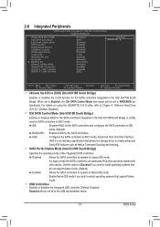
... CMOS Setup Utility-Copyright (C) 1984-2011 Award Software Integrated Peripherals eXtreme Hard Drive (XHD) ICH SATA Control Mode SATA Port0-3 Native Mode USB Controllers USB Keyboard Function USB Mouse Function USB Storage Function Azalia Codec Onboard H/W LAN Green LAN } SMART LAN Onboard LAN Boot ROM Onboard USB 3.0 Controller GSATA3 6_7/IDE Controller GSATA3 6_7/IDE Ctrl Mode [Disabled] [IDE] [Disabled] [Enabled] [Enabled] [Disabled] [Enabled] [Auto] [Enabled] [Disabled] [Press Enter] [Disabled] [Enabled] [Enabled] [IDE] Item Help Menu...
... CMOS Setup Utility-Copyright (C) 1984-2011 Award Software Integrated Peripherals eXtreme Hard Drive (XHD) ICH SATA Control Mode SATA Port0-3 Native Mode USB Controllers USB Keyboard Function USB Mouse Function USB Storage Function Azalia Codec Onboard H/W LAN Green LAN } SMART LAN Onboard LAN Boot ROM Onboard USB 3.0 Controller GSATA3 6_7/IDE Controller GSATA3 6_7/IDE Ctrl Mode [Disabled] [IDE] [Disabled] [Enabled] [Enabled] [Disabled] [Enabled] [Auto] [Enabled] [Disabled] [Press Enter] [Disabled] [Enabled] [Enabled] [IDE] Item Help Menu...
Manual
Page 53
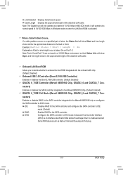
... attached LAN cable. When a Cable Problem Occurs... Onboard LAN Boot ROM Allows you to decide whether to AHCI mode. BIOS Setup Note: Part 4-5 and Part 7-8 are not used in a 10/100 Mbps environment, so their Status fields will show Short and then length shown will be the approximate distance to enable advanced Serial ATA features such as Native Command Queuing and hot plug. - 53 - nectors) Enables or disables RAID for the SATA controller integrated...
... attached LAN cable. When a Cable Problem Occurs... Onboard LAN Boot ROM Allows you to decide whether to AHCI mode. BIOS Setup Note: Part 4-5 and Part 7-8 are not used in a 10/100 Mbps environment, so their Status fields will show Short and then length shown will be the approximate distance to enable advanced Serial ATA features such as Native Command Queuing and hot plug. - 53 - nectors) Enables or disables RAID for the SATA controller integrated...

Manual
Page 69
... supports USB flash drive or hard drives using FAT32/16/12 file system. • If the BIOS update file is saved to a hard drive in RAID/AHCI mode or a hard drive attached to an independent SATA controller, use the up or down arrow key to select Update BIOS from Drive Save BIOS to begin the BIOS update. Make sure the BIOS update file matches your motherboard model. In the main menu of the system reading the BIOS file from Drive Please SparevsesBaInOySketoy Dtoricvoentinue Enter : Run hi:Move ESC:Reset F10:Power...
... supports USB flash drive or hard drives using FAT32/16/12 file system. • If the BIOS update file is saved to a hard drive in RAID/AHCI mode or a hard drive attached to an independent SATA controller, use the up or down arrow key to select Update BIOS from Drive Save BIOS to begin the BIOS update. Make sure the BIOS update file matches your motherboard model. In the main menu of the system reading the BIOS file from Drive Please SparevsesBaInOySketoy Dtoricvoentinue Enter : Run hi:Move ESC:Reset F10:Power...
Manual
Page 79
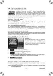
... to access the Intel Rapid Storage Technology, with which you run the X.H.D utility, back up a RAID 0 array later using the Auto function. - 79 - Setting Up a RAID-Ready System Step 1: Configure the system BIOS Enter the system BIOS Setup program, set up a RAID array: (Note 3) Click Manual to Chapter 5, "Installing the SATA RAID/AHCI Driver and Operating System." ) Step 3: Install the motherboard drivers and the X.H.D utiltiy After installing the operating system, insert the motherboard driver disk. Without the driver, the hard drive may...
... to access the Intel Rapid Storage Technology, with which you run the X.H.D utility, back up a RAID 0 array later using the Auto function. - 79 - Setting Up a RAID-Ready System Step 1: Configure the system BIOS Enter the system BIOS Setup program, set up a RAID array: (Note 3) Click Manual to Chapter 5, "Installing the SATA RAID/AHCI Driver and Operating System." ) Step 3: Install the motherboard drivers and the X.H.D utiltiy After installing the operating system, insert the motherboard driver disk. Without the driver, the hard drive may...
Manual
Page 81
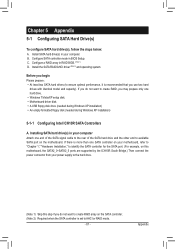
...; Motherboard driver disk. • A USB floppy disk drive (needed during Windows XP installation) • An empty formatted floppy disk (needed during Windows XP installation) 5-1-1 Configuring Intel ICH10R SATA Controllers A. Install the SATA RAID/AHCI driver (Note 2) and operating system. C. If there is more than one SATA controller on your motherboard, refer to "Chapter 1," "Hardware Installation," to identify the SATA controller for the SATA port. (For example, on this motherboard, the SATA2_0~SATA2_5 ports are supported by the ICH10R South Bridge.) Then connect the power connector...
...; Motherboard driver disk. • A USB floppy disk drive (needed during Windows XP installation) • An empty formatted floppy disk (needed during Windows XP installation) 5-1-1 Configuring Intel ICH10R SATA Controllers A. Install the SATA RAID/AHCI driver (Note 2) and operating system. C. If there is more than one SATA controller on your motherboard, refer to "Chapter 1," "Hardware Installation," to identify the SATA controller for the SATA port. (For example, on this motherboard, the SATA2_0~SATA2_5 ports are supported by the ICH10R South Bridge.) Then connect the power connector...

Manual
Page 89
...- Installing SATA hard drive(s) in system BIOS Setup. Then connect the power connector from the exact settings for your computer and press to Integrated Peripherals. In BIOS Setup, go to enter BIOS Setup during the POST. erboard. CMOS Setup Utility-Copyright (C) 1984-2011 Award Software Integrated Peripherals eXtreme Hard Drive (XHD) ICH SATA Control Mode SATA Port0-3 Native Mode USB Controllers USB Keyboard Function USB Mouse Function USB Storage Function Azalia Codec Onboard H/W LAN Green LAN } SMART LAN Onboard LAN Boot ROM Onboard...
...- Installing SATA hard drive(s) in system BIOS Setup. Then connect the power connector from the exact settings for your computer and press to Integrated Peripherals. In BIOS Setup, go to enter BIOS Setup during the POST. erboard. CMOS Setup Utility-Copyright (C) 1984-2011 Award Software Integrated Peripherals eXtreme Hard Drive (XHD) ICH SATA Control Mode SATA Port0-3 Native Mode USB Controllers USB Keyboard Function USB Mouse Function USB Storage Function Azalia Codec Onboard H/W LAN Green LAN } SMART LAN Onboard LAN Boot ROM Onboard...

Manual
Page 95
...\AHCI\Win32 AHCI driver for Windows 64-bit: \BootDrv\Marvell\AHCI\win64 Step 3: When a screen as the example operating system.) For the Intel ICH10R: As Windows 7 and Vista already include Intel SATA RAID/AHCI driver, you install all required drivers from the Windows 7/Vista setup disk and perform standard OS installation steps. Appendix screen, select Load Driver. For the Marvell 88SE9182: Step 1: Boot from the motherboard driver disk using "Xpress Install" to ensure system performance and compatibility. The locations...
...\AHCI\Win32 AHCI driver for Windows 64-bit: \BootDrv\Marvell\AHCI\win64 Step 3: When a screen as the example operating system.) For the Intel ICH10R: As Windows 7 and Vista already include Intel SATA RAID/AHCI driver, you install all required drivers from the Windows 7/Vista setup disk and perform standard OS installation steps. Appendix screen, select Load Driver. For the Marvell 88SE9182: Step 1: Boot from the motherboard driver disk using "Xpress Install" to ensure system performance and compatibility. The locations...
Manual
Page 96
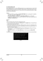
... 8) Intel Rapid Storage driver for 32bit system for Windows XP 32-bit op- Select the controller driver by pressing the corresponding letter from the motherboard driver disk to your floppy disk. Press any key to the methods below. Installing Windows XP Before installing Windows XP, connect a USB floppy disk drive to a floppy disk. Method A: • For the Intel ICH10R, copy all files in the BootDrv folder. For AHCI mode, depending on whether you 're using a USB floppy disk drive, make sure...
... 8) Intel Rapid Storage driver for 32bit system for Windows XP 32-bit op- Select the controller driver by pressing the corresponding letter from the motherboard driver disk to your floppy disk. Press any key to the methods below. Installing Windows XP Before installing Windows XP, connect a USB floppy disk drive to a floppy disk. Method A: • For the Intel ICH10R, copy all files in the BootDrv folder. For AHCI mode, depending on whether you 're using a USB floppy disk drive, make sure...
Manual
Page 98
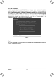
... floppy disk containing the SATA RAID/AHCI driver and press . Both of the two drivers appear on whether you are installing the 32-bit version. When both of the Marvell shared library and Marvell 91xx SATA RAID Controller need to be installed. Select the SCSI Adapter you can proceed with Windows, using a device support disk provided by an adapter manufacturer. Windows Setup You have chosen to the screen in Figure 4. After the driver installation...
... floppy disk containing the SATA RAID/AHCI driver and press . Both of the two drivers appear on whether you are installing the 32-bit version. When both of the Marvell shared library and Marvell 91xx SATA RAID Controller need to be installed. Select the SCSI Adapter you can proceed with Windows, using a device support disk provided by an adapter manufacturer. Windows Setup You have chosen to the screen in Figure 4. After the driver installation...
Manual
Page 109
... problems. (For reference only.) 1 short: System boots successfully 2 short: CMOS setting error 1 long, 9 short: BIOS ROM error 1 long, 1 short: Memory or motherboard error Continuous long beeps: Graphics card not inserted properly 1 long, 2 short: Monitor or graphics card error Continuous short beeps: Power error 1 long, 3 short: Keyboard error - 109 - Appendix You can temporarily remove the battery from GIGABYTE's website to the maximum volume? Then make sure Service Pack 1 or Service Pack 2 has been installed (check in the BIOS Setup program. Q: What do the beeps...
... problems. (For reference only.) 1 short: System boots successfully 2 short: CMOS setting error 1 long, 9 short: BIOS ROM error 1 long, 1 short: Memory or motherboard error Continuous long beeps: Graphics card not inserted properly 1 long, 2 short: Monitor or graphics card error Continuous short beeps: Power error 1 long, 3 short: Keyboard error - 109 - Appendix You can temporarily remove the battery from GIGABYTE's website to the maximum volume? Then make sure Service Pack 1 or Service Pack 2 has been installed (check in the BIOS Setup program. Q: What do the beeps...

Manual
Page 114
... onboard COM ports if the corresponding item in Setup & Auto-configuration table 1. USB final Initialization 2. Set up floppy related fields in stack back to all IDE devices: HDD, LS120, ZIP, CDROM... Enable/Disable Parity Check according to enter Setup utility; APM initialization Clear noise of the memory 1. Assign resources to CMOS Initialize ISA PnP boot devices 1. If no errors occur or F1 key is supported - Recover the text fond used by EPA logo (not for keys - POST...
... onboard COM ports if the corresponding item in Setup & Auto-configuration table 1. USB final Initialization 2. Set up floppy related fields in stack back to all IDE devices: HDD, LS120, ZIP, CDROM... Enable/Disable Parity Check according to enter Setup utility; APM initialization Clear noise of the memory 1. Assign resources to CMOS Initialize ISA PnP boot devices 1. If no errors occur or F1 key is supported - Recover the text fond used by EPA logo (not for keys - POST...


