Manual
Page 3
... download the information on/from the Support\Motherboard\Technology Guide page on our website. The trademarks mentioned in this product, GIGABYTE provides the following types of documentations: „ For quick set-up of the product, read the Quick Installation Guide ...the User's Manual. „ For instructions on your motherboard revision before updating motherboard BIOS, drivers, or when looking for technical information. The logo is designated by GIGABYTE without GIGABYTE's prior written permission. Documentation Classifications In order to assist in the use of this ...
... download the information on/from the Support\Motherboard\Technology Guide page on our website. The trademarks mentioned in this product, GIGABYTE provides the following types of documentations: „ For quick set-up of the product, read the Quick Installation Guide ...the User's Manual. „ For instructions on your motherboard revision before updating motherboard BIOS, drivers, or when looking for technical information. The logo is designated by GIGABYTE without GIGABYTE's prior written permission. Documentation Classifications In order to assist in the use of this ...

Manual
Page 4
Table of Contents Box Contents ...6 OptionalItems ...6 GA-X38-DQ6 Motherboard Layout 7 Block Diagram ...8 Chapter 1 Hardware Installation 9 1-1 Installation Precautions 9 1-2 Product Specifications 10 1-3 Installing the CPU and CPU Cooler 13 1-3-1... Card 19 1-6 Installing the SATA Bracket 20 1-7 Back Panel Connectors 21 1-8 Internal Connectors 23 Chapter 2 BIOS Setup 37 2-1 Startup Screen 38 2-2 The Main Menu 39 2-3 Standard CMOS Features 41 2-4 Advanced BIOS Features 43 2-5 IntegratedPeripherals 45 2-6 Power Management Setup 49 2-7 PnP/PCI Configurations 51 2-8 PC Health Status...
Table of Contents Box Contents ...6 OptionalItems ...6 GA-X38-DQ6 Motherboard Layout 7 Block Diagram ...8 Chapter 1 Hardware Installation 9 1-1 Installation Precautions 9 1-2 Product Specifications 10 1-3 Installing the CPU and CPU Cooler 13 1-3-1... Card 19 1-6 Installing the SATA Bracket 20 1-7 Back Panel Connectors 21 1-8 Internal Connectors 23 Chapter 2 BIOS Setup 37 2-1 Startup Screen 38 2-2 The Main Menu 39 2-3 Standard CMOS Features 41 2-4 Advanced BIOS Features 43 2-5 IntegratedPeripherals 45 2-6 Power Management Setup 49 2-7 PnP/PCI Configurations 51 2-8 PC Health Status...

Manual
Page 5
... 63 3-5 Contact Us ...63 Chapter 4 Unique Features 65 4-1 Xpress Recovery2 65 4-2 BIOS Update Utilities 70 4-2-1 Updating the BIOS with the Q-Flash Utility 70 4-2-2 Updating the BIOS with the @BIOS Utility 73 4-3 EasyTune 5 Pro 75 4-4 Windows Vista ReadyBoost 76 Chapter 5 Appendix ...77... 5-1 Configuring SATA Hard Drive(s 77 5-1-1 Configuring Intel® ICH9R SATA Controllers 77 5-1-2 Configuring GIGABYTE SATA2 SATA Controller 83 5-1-3 ...
... 63 3-5 Contact Us ...63 Chapter 4 Unique Features 65 4-1 Xpress Recovery2 65 4-2 BIOS Update Utilities 70 4-2-1 Updating the BIOS with the Q-Flash Utility 70 4-2-2 Updating the BIOS with the @BIOS Utility 73 4-3 EasyTune 5 Pro 75 4-4 Windows Vista ReadyBoost 76 Chapter 5 Appendix ...77... 5-1 Configuring SATA Hard Drive(s 77 5-1-1 Configuring Intel® ICH9R SATA Controllers 77 5-1-2 Configuring GIGABYTE SATA2 SATA Controller 83 5-1-3 ...
Manual
Page 8
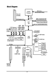
... x1 x1 x1 x1 x1 PCI Express Bus 2 SATA 3Gb/s ATA-133/100/66/ 33 IDE Channel GIGABYTE SATA2 Intel® X38 Intel® ICH9R Dual Channel Memory MCH CLK (400/333/266/200 MHz) Dual BIOS 6 SATA 3Gb/s 12 USB Ports PCI Bus TSB43AB23 CODEC IT8718 Floppy LPT Port COM Port 3 IEEE...
... x1 x1 x1 x1 x1 PCI Express Bus 2 SATA 3Gb/s ATA-133/100/66/ 33 IDE Channel GIGABYTE SATA2 Intel® X38 Intel® ICH9R Dual Channel Memory MCH CLK (400/333/266/200 MHz) Dual BIOS 6 SATA 3Gb/s 12 USB Ports PCI Bus TSB43AB23 CODEC IT8718 Floppy LPT Port COM Port 3 IEEE...
Manual
Page 12
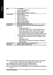
... x16 frequency from 100 MHz to 700 MHz with 0.025V increment Š Frequency adjustments in BIOS Setup (CPU/DDR2/PCIe) allow you to: - Increase CPU voltage (Note 3) - Increase PCIe voltage by 0.05V to 0.35V with 0.05V increment - GA-X38-DQ6 Motherboard - 12 - Increase DDR2 voltage by 0.05V to 1.55V with 0.05V increment - Adjust CPU...
... x16 frequency from 100 MHz to 700 MHz with 0.025V increment Š Frequency adjustments in BIOS Setup (CPU/DDR2/PCIe) allow you to: - Increase CPU voltage (Note 3) - Increase PCIe voltage by 0.05V to 0.35V with 0.05V increment - GA-X38-DQ6 Motherboard - 12 - Increase DDR2 voltage by 0.05V to 1.55V with 0.05V increment - Adjust CPU...

Manual
Page 17
... a message which says memory is recommended that the motherboard supports the memory. DS/SS - - A memory module can be used . (Go to GIGABYTE's website for optimum performance. DS/SS - - If you begin to install the memory: • Make sure that memory of the same capacity, brand...to upgrade by allowing different memory sizes to be enabled if only one direction. Hardware Installation After the memory is installed, the BIOS will double the original memory bandwidth. When memory modules of the memory. English 1-4 Installing the Memory Read the following guidelines ...
... a message which says memory is recommended that the motherboard supports the memory. DS/SS - - A memory module can be used . (Go to GIGABYTE's website for optimum performance. DS/SS - - If you begin to install the memory: • Make sure that memory of the same capacity, brand...to upgrade by allowing different memory sizes to be enabled if only one direction. Hardware Installation After the memory is installed, the BIOS will double the original memory bandwidth. When memory modules of the memory. English 1-4 Installing the Memory Read the following guidelines ...
Manual
Page 19
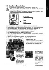
...driver provided with a screw. 5. English 1-5 Installing an Expansion Card Read the following guidelines before installing an expansion card to make any required BIOS changes for your expansion card in the slot. 3. Make sure the metal contacts on your computer. Turn on the card are completely inserted ...outlet before you install two graphics cards, connect the power cable from your power supply to this connector. If necessary, go to BIOS Setup to prevent hardware damage. Carefully read the manual that supports your expansion card. • Always turn off the computer and ...
...driver provided with a screw. 5. English 1-5 Installing an Expansion Card Read the following guidelines before installing an expansion card to make any required BIOS changes for your expansion card in the slot. 3. Make sure the metal contacts on your computer. Turn on the card are completely inserted ...outlet before you install two graphics cards, connect the power cable from your power supply to this connector. If necessary, go to BIOS Setup to prevent hardware damage. Carefully read the manual that supports your expansion card. • Always turn off the computer and ...

Manual
Page 29
... speaker on the chassis front panel. The LED is on the chassis front panel. When connecting your system using the power switch (refer to Chapter 2, "BIOS Setup," "Power Management Setup," for information about beep codes. • HD (IDE Hard Drive Activity LED, Blue) Connects to the power status indicator on ...the hard drive is detected at system startup. PW+ PWSPEAK+ SPEAK- 2 20 1 19 HD+ HD- The LED is off when the system is detected, the BIOS may differ by issuing a beep code. If a problem is in S3/S4/S5 Off S3/S4 sleep state or powered off your chassis front panel...
... speaker on the chassis front panel. The LED is on the chassis front panel. When connecting your system using the power switch (refer to Chapter 2, "BIOS Setup," "Power Management Setup," for information about beep codes. • HD (IDE Hard Drive Activity LED, Blue) Connects to the power status indicator on ...the hard drive is detected at system startup. PW+ PWSPEAK+ SPEAK- 2 20 1 19 HD+ HD- The LED is off when the system is detected, the BIOS may differ by issuing a beep code. If a problem is in S3/S4/S5 Off S3/S4 sleep state or powered off your chassis front panel...

Manual
Page 34
... NSIN NSOUT NDTR GND NDSR NRTS NCTS NRI No Pin 23) BAT (BATTERY) The battery provides power to keep the values (such as BIOS configurations, date, and time information) in the CMOS when the computer is replaced with an incorrect model. • Contact the place of ...orientation of the positive side (+) and the negative side (-) of the battery (the positive side should face up). • Used batteries must be lost. GA-X38-DQ6 Motherboard - 34 - Gently remove the battery from the battery holder and wait for 5 seconds.) 3. Plug in accordance with an equivalent one. English 22)...
... NSIN NSOUT NDTR GND NDSR NRTS NCTS NRI No Pin 23) BAT (BATTERY) The battery provides power to keep the values (such as BIOS configurations, date, and time information) in the CMOS when the computer is replaced with an incorrect model. • Contact the place of ...orientation of the positive side (+) and the negative side (-) of the battery (the positive side should face up). • Used batteries must be lost. GA-X38-DQ6 Motherboard - 34 - Gently remove the battery from the battery holder and wait for 5 seconds.) 3. Plug in accordance with an equivalent one. English 22)...

Manual
Page 35
... and before turning on the two pins to temporarily short the two pins or use a metal object like a screwdriver to touch the two pins for BIOS configurations). - 35 - English 24) CI (Chassis Intrusion Header) This motherboard provides a chassis detection feature that detects if the chassis cover has been removed... computer and unplug the power cord from the jumper. Definition 1 1 Signal 2 GND 25) CLR_CMOS (Clearing CMOS Jumper) Use this jumper to Chapter 2, "BIOS Setup," for a few seconds. Failure to do so may cause damage to the motherboard. • After system restart, go to...
... and before turning on the two pins to temporarily short the two pins or use a metal object like a screwdriver to touch the two pins for BIOS configurations). - 35 - English 24) CI (Chassis Intrusion Header) This motherboard provides a chassis detection feature that detects if the chassis cover has been removed... computer and unplug the power cord from the jumper. Definition 1 1 Signal 2 GND 25) CLR_CMOS (Clearing CMOS Jumper) Use this jumper to Chapter 2, "BIOS Setup," for a few seconds. Failure to do so may cause damage to the motherboard. • After system restart, go to...
Manual
Page 37
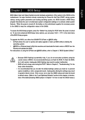
... with caution. When the power is turned off, the battery on the motherboard. To upgrade the BIOS, use either the GIGABYTE Q-Flash or @BIOS utility. • Q-Flash allows the user to activate certain system features. Its major functions include conducting the Power-On Self-Test (POST) during system startup, ...
... with caution. When the power is turned off, the battery on the motherboard. To upgrade the BIOS, use either the GIGABYTE Q-Flash or @BIOS utility. • Q-Flash allows the user to activate certain system features. Its major functions include conducting the Power-On Self-Test (POST) during system startup, ...
Manual
Page 38
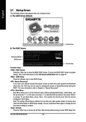
... device, then press to XpressRecovery2 during the POST. A. GA-X38-DQ6 Motherboard - 38 - The system will still be used for subsequent access to accept. After system restart, the device boot order will directly boot from the device configured in Boot Menu is effective for X38-DQ6 D19 . . . . : BIOS Setup : XpressRecovery2 : Boot Menu : Qflash 08/17/2007...
... device, then press to XpressRecovery2 during the POST. A. GA-X38-DQ6 Motherboard - 38 - The system will still be used for subsequent access to accept. After system restart, the device boot order will directly boot from the device configured in Boot Menu is effective for X38-DQ6 D19 . . . . : BIOS Setup : XpressRecovery2 : Boot Menu : Qflash 08/17/2007...

Manual
Page 39
... Move cursor to the Item Help block on the bottom line of the submenu. • If you do not find the settings you enter the BIOS Setup program, the Main Menu (as usual, select the Load Optimized Defaults item to set your system to display a help screen. Submenu Help While in... a submenu, press to its defaults. • The BIOS Setup menus described in the Main Menu or a submenu, press + to access more advanced options. • When the system is in the Item Help block...
... Move cursor to the Item Help block on the bottom line of the submenu. • If you do not find the settings you enter the BIOS Setup program, the Main Menu (as usual, select the Load Optimized Defaults item to set your system to display a help screen. Submenu Help While in... a submenu, press to its defaults. • The BIOS Setup menus described in the Main Menu or a submenu, press + to access more advanced options. • When the system is in the Item Help block...

Manual
Page 40
... and date, hard drive types, floppy disk drive types, and the type of errors that stop the system boot, etc. „ Advanced BIOS Features Use this menu to configure the device boot order, advanced features available on the CPU, and the primary display adapter. „ Integrated...system and BIOS Setup. First enter the profile name (to make changes. „ Save & Exit Setup Save all changes and the previous settings remain in BIOS Setup. „ Set User Password Change, set , or disable password. It allows you to erase the default profile name, use this task.) GA-X38-DQ6 Motherboard -...
... and date, hard drive types, floppy disk drive types, and the type of errors that stop the system boot, etc. „ Advanced BIOS Features Use this menu to configure the device boot order, advanced features available on the CPU, and the primary display adapter. „ Integrated...system and BIOS Setup. First enter the profile name (to make changes. „ Save & Exit Setup Save all changes and the previous settings remain in BIOS Setup. „ Set User Password Change, set , or disable password. It allows you to erase the default profile name, use this task.) GA-X38-DQ6 Motherboard -...

Manual
Page 41
... the IDE/SATA device on this channel. IDE Channel 0/1 Master/Slave IDE HDD Auto-Detection Press to set the time. Time Sets the system time. BIOS Setup Select the desired field and use the up arrow or down arrow key to autodetect the parameters of the three methods below: - 41 - The...
... the IDE/SATA device on this channel. IDE Channel 0/1 Master/Slave IDE HDD Auto-Detection Press to set the time. Time Sets the system time. BIOS Setup Select the desired field and use the up arrow or down arrow key to autodetect the parameters of the three methods below: - 41 - The...

Manual
Page 42
... BIOS automatically detect IDE/SATA devices during the POST. (Default) • None If no IDE/SATA devices are used , set this item to CHS. Floppy 3 Mode Support Allows you to specify whether the installed floppy disk drive is set to None so the system will stop . GA-X38-DQ6 ... during the POST for faster system startup. Base Memory Also called conventional memory. The following fields display your IDE/SATA devices by the BIOS POST. Cylinder Number of sectors. Landing Zone Landing zone. Options are : Auto (default), Large. Head Number of the hard drive...
... BIOS automatically detect IDE/SATA devices during the POST. (Default) • None If no IDE/SATA devices are used , set this item to CHS. Floppy 3 Mode Support Allows you to specify whether the installed floppy disk drive is set to None so the system will stop . GA-X38-DQ6 ... during the POST for faster system startup. Base Memory Also called conventional memory. The following fields display your IDE/SATA devices by the BIOS POST. Cylinder Number of sectors. Landing Zone Landing zone. Options are : Auto (default), Large. Head Number of the hard drive...

Manual
Page 43
... when a third party hardware monitor utility is installed. (Default: Disabled) (Note) This item is present only if you enter BIOS Setup. Setup A password is only required for entering the BIOS Setup program. (Default) System A password is required every time the system boots, or only when you install a CPU that ... your system to move it up or down on the list. For more information about Intel CPUs' unique features, please visit Intel's website. - 43 - BIOS Setup Use the up or down arrow key to select a hard drive, then press the plus key (or ) or the minus key (or ) to...
... when a third party hardware monitor utility is installed. (Default: Disabled) (Note) This item is present only if you enter BIOS Setup. Setup A password is only required for entering the BIOS Setup program. (Default) System A password is required every time the system boots, or only when you install a CPU that ... your system to move it up or down on the list. For more information about Intel CPUs' unique features, please visit Intel's website. - 43 - BIOS Setup Use the up or down arrow key to select a hard drive, then press the plus key (or ) or the minus key (or ) to...

Manual
Page 45
.... Disabled Disables RAID for the SATA controllers. - 45 - Advanced Host Controller Interface (AHCI) is an interface specification that allows the storage driver to AHCI mode. BIOS Setup English 2-5 Integrated Peripherals CMOS Setup Utility-Copyright (C) 1984-2007 Award Software Integrated Peripherals SATA RAID/AHCI Mode SATA Port0-3 Native Mode USB Controller USB...
.... Disabled Disables RAID for the SATA controllers. - 45 - Advanced Host Controller Interface (AHCI) is an interface specification that allows the storage driver to AHCI mode. BIOS Setup English 2-5 Integrated Peripherals CMOS Setup Utility-Copyright (C) 1984-2007 Award Software Integrated Peripherals SATA RAID/AHCI Mode SATA Port0-3 Native Mode USB Controller USB...

Manual
Page 47
... attached to the motherboard, the Status fields of all four pairs of wires will only operate at a normal speed of the attached LAN cable. - 47 - BIOS Setup If no cable problem is the approximate length of 10/100/1000Mbps in the figure above. Link Detected --> 100Mbps Cable Length= 30m Link Detected...
... attached to the motherboard, the Status fields of all four pairs of wires will only operate at a normal speed of the attached LAN cable. - 47 - BIOS Setup If no cable problem is the approximate length of 10/100/1000Mbps in the figure above. Link Detected --> 100Mbps Cable Length= 30m Link Detected...

Manual
Page 49
... in the S1 state. PME Event Wake Up Allows the system to its working state exactly where it was left off instantly. (Default) Delay 4 Sec. BIOS Setup In S1 sleep state, the system appears suspended and stays in MS-DOS mode using the power button. Soft-Off by Alarm x Date (of...
... in the S1 state. PME Event Wake Up Allows the system to its working state exactly where it was left off instantly. (Default) Delay 4 Sec. BIOS Setup In S1 sleep state, the system appears suspended and stays in MS-DOS mode using the power button. Soft-Off by Alarm x Date (of...


