
Manual
Page 1
...operating system The X.H.D utility supports Windows 7/Vista/XP. Setting Up a RAID-Ready System Step 1: Configure the system BIOS Enter the system BIOS Setup program, set eXtreme Hard Drive (X.H.D) under the Integrated Peripherals menu to Enabled to set up a RAID-ready system... exit the X.H.D utility. (Note 1) The X.H.D utility only supports the SATA controllers integrated in the array. ) 1. eXtreme Hard Drive (X.H.D) With GIGABYTE eXtreme Hard Drive (X.H.D)(Note 1), users can build a RAID 0, RAID 1, or other supported RAID array depending on your needs and hardware components. 3....
...operating system The X.H.D utility supports Windows 7/Vista/XP. Setting Up a RAID-Ready System Step 1: Configure the system BIOS Enter the system BIOS Setup program, set eXtreme Hard Drive (X.H.D) under the Integrated Peripherals menu to Enabled to set up a RAID-ready system... exit the X.H.D utility. (Note 1) The X.H.D utility only supports the SATA controllers integrated in the array. ) 1. eXtreme Hard Drive (X.H.D) With GIGABYTE eXtreme Hard Drive (X.H.D)(Note 1), users can build a RAID 0, RAID 1, or other supported RAID array depending on your needs and hardware components. 3....

Manual
Page 2
Configuring the Smart TPM Utility 18 4.1. Installing the Infineon TPM Driver and the Smart TPM Utility 4 2.1. Initializing the TPM Chip with the Smart TPM Utility 5 3.2. Creating a Bluetooth Cell Phone Key 19 4.3. Installing the Infineon TPM Driver 4 2.2. Other Bluetooth Settings 21 4.4. Initializing the TPM chip 5 3.1. Installing the Smart TPM Utility 4 3. Advanced Mode...8 4. Other Features...21 - 2 - Table of Contents TPM Configuration Procedure 3 1. Configuring the System BIOS 3 2. Creating a USB Key 18 4.2.
Configuring the Smart TPM Utility 18 4.1. Installing the Infineon TPM Driver and the Smart TPM Utility 4 2.1. Initializing the TPM Chip with the Smart TPM Utility 5 3.2. Creating a Bluetooth Cell Phone Key 19 4.3. Installing the Infineon TPM Driver 4 2.2. Other Bluetooth Settings 21 4.4. Initializing the TPM chip 5 3.1. Installing the Smart TPM Utility 4 3. Advanced Mode...8 4. Other Features...21 - 2 - Table of Contents TPM Configuration Procedure 3 1. Configuring the System BIOS 3 2. Creating a USB Key 18 4.2.

Manual
Page 3
... this setting) to Enabled/Activate. Go to save changes and then exit the BIOS Setup program. To activate the TPM chip, set the User Password in sequence: 1. Configuring the system BIOS 2. CMOS Setup Utility-Copyright (C) 1984-2009 Award Software Security Chip Configuration Security ...utility 3. Previously encrypted files will appear. Step 1: As the computer starts, enter the BIOS Setup program. It's recommended that you use the TPM functionality, first enter the system BIOS Setup to back up the encrypted files first. To prevent the TPM settings being cleared...
... this setting) to Enabled/Activate. Go to save changes and then exit the BIOS Setup program. To activate the TPM chip, set the User Password in sequence: 1. Configuring the system BIOS 2. CMOS Setup Utility-Copyright (C) 1984-2009 Award Software Security Chip Configuration Security ...utility 3. Previously encrypted files will appear. Step 1: As the computer starts, enter the BIOS Setup program. It's recommended that you use the TPM functionality, first enter the system BIOS Setup to back up the encrypted files first. To prevent the TPM settings being cleared...

Manual
Page 5
... key using your PSD data when connecting to the Bluetooth cell phone or when plugging in Section 3.1). Initializing the TPM chip After configuring the system BIOS and installing the driver software, the Infineon Security Platform icon , which your own password. Personal Secure Drive (PSD)" settings only.
... key using your PSD data when connecting to the Bluetooth cell phone or when plugging in Section 3.1). Initializing the TPM chip After configuring the system BIOS and installing the driver software, the Infineon Security Platform icon , which your own password. Personal Secure Drive (PSD)" settings only.

Manual
Page 6
... provided after setup, so please ensure that you specify is 16 characters). Please note that the size you cannot use the Security Platform in the BIOS Setup program. • This password incorporates the functionalities of the "Owner Password," "User Password," "Emergency Recovery Token Password," and "Password Reset Token Password" of the...
... provided after setup, so please ensure that you specify is 16 characters). Please note that the size you cannot use the Security Platform in the BIOS Setup program. • This password incorporates the functionalities of the "Owner Password," "User Password," "Emergency Recovery Token Password," and "Password Reset Token Password" of the...

Manual
Page 7
... phone. Selecting the Enable Backup to search for pairing. You can select more than one user stores their encrypted TPM User Passwords in the system BIOS. Create a Bluetooth cell phone key: Select the Use Bluetooth Device check box and click Refresh to... BIOS check box will store the encrypted TPM User Password in the BIOS, the latter will appear. Step 3: Create Your Smart TPM Key 1. If more than one USB flash drive at the same time. Then enter the...
... phone. Selecting the Enable Backup to search for pairing. You can select more than one user stores their encrypted TPM User Passwords in the system BIOS. Create a Bluetooth cell phone key: Select the Use Bluetooth Device check box and click Refresh to... BIOS check box will store the encrypted TPM User Password in the BIOS, the latter will appear. Step 3: Create Your Smart TPM Key 1. If more than one USB flash drive at the same time. Then enter the...

Manual
Page 18
... cell phone/USB flash drive key, so when they lost a key they still can access/close their encrypted TPM User Passwords in the BIOS, the latter will render the files encrypted via the TPM unable to be sure to store them in a secure location and back them ...menu as a result of complicated configurations. Creating a USB Key Step 1: After initializing the TPM chip and setting up . Configuring the Smart TPM Utility GIGABYTE's unique Smart TPM (Trusted Platform Module) supports the industry's most advanced hardwarebased data encryption. Smart TPM provides users with the TPM, be cracked or ...
... cell phone/USB flash drive key, so when they lost a key they still can access/close their encrypted TPM User Passwords in the BIOS, the latter will render the files encrypted via the TPM unable to be sure to store them in a secure location and back them ...menu as a result of complicated configurations. Creating a USB Key Step 1: After initializing the TPM chip and setting up . Configuring the Smart TPM Utility GIGABYTE's unique Smart TPM (Trusted Platform Module) supports the industry's most advanced hardwarebased data encryption. Smart TPM provides users with the TPM, be cracked or ...

Manual
Page 19
You are able to access/close your PSD by plugging in BIOS Setup and then set earlier and click OK to complete creating the USB key. When prompted to confirm, click Yes. To be locked. To cancel a ...
You are able to access/close your PSD by plugging in BIOS Setup and then set earlier and click OK to complete creating the USB key. When prompted to confirm, click Yes. To be locked. To cancel a ...
Manual
Page 3
.... The trademarks mentioned in this manual may be made by GIGABYTE without GIGABYTE's prior written permission. For detailed product information, carefully read or download the information on/from the Support&Downloads\Motherboard\Technology Guide page on your motherboard revision before updating motherboard BIOS, drivers, or when looking for technical information. Check your motherboard...
.... The trademarks mentioned in this manual may be made by GIGABYTE without GIGABYTE's prior written permission. For detailed product information, carefully read or download the information on/from the Support&Downloads\Motherboard\Technology Guide page on your motherboard revision before updating motherboard BIOS, drivers, or when looking for technical information. Check your motherboard...
Manual
Page 4
Table of Contents Box Contents...6 Optional Items...6 GA-P55A-UD6 Motherboard Layout 7 Block Diagram...8 Chapter 1 Hardware Installation 9 1-1 Installation Precautions 9 1-2 Product Specifications 10 1-3 Installing the CPU and CPU Cooler 13 1-3-1 ...Back Panel Connectors 21 1-9 Onboard LEDs and Buttons 23 1-10 Internal Connectors 25 Chapter 2 BIOS Setup 35 2-1 Startup Screen 36 2-2 The Main Menu 37 2-3 MB Intelligent Tweaker(M.I.T 39 2-4 Standard CMOS Features 49 2-5 Advanced BIOS Features 51 2-6 Integrated Peripherals 53 2-7 Power Management Setup 57 2-8 PC Health Status 59 ...
Table of Contents Box Contents...6 Optional Items...6 GA-P55A-UD6 Motherboard Layout 7 Block Diagram...8 Chapter 1 Hardware Installation 9 1-1 Installation Precautions 9 1-2 Product Specifications 10 1-3 Installing the CPU and CPU Cooler 13 1-3-1 ...Back Panel Connectors 21 1-9 Onboard LEDs and Buttons 23 1-10 Internal Connectors 25 Chapter 2 BIOS Setup 35 2-1 Startup Screen 36 2-2 The Main Menu 37 2-3 MB Intelligent Tweaker(M.I.T 39 2-4 Standard CMOS Features 49 2-5 Advanced BIOS Features 51 2-6 Integrated Peripherals 53 2-7 Power Management Setup 57 2-8 PC Health Status 59 ...

Manual
Page 5
... 66 3-4 Contact...67 3-5 System...67 3-6 Download Center 68 3-7 New Utilities...68 Chapter 4 Unique Features 69 4-1 Xpress Recovery2 69 4-2 BIOS Update Utilities 72 4-2-1 Updating the BIOS with the Q-Flash Utility 72 4-2-2 Updating the BIOS with the @BIOS Utility 75 4-3 EasyTune 6...76 4-4 Dynamic Energy Saver™ 2 77 4-5 Q-Share...79 4-6 Smart 6™ ...80 4-7 Smart TPM ...83 4-8 Auto...
... 66 3-4 Contact...67 3-5 System...67 3-6 Download Center 68 3-7 New Utilities...68 Chapter 4 Unique Features 69 4-1 Xpress Recovery2 69 4-2 BIOS Update Utilities 72 4-2-1 Updating the BIOS with the Q-Flash Utility 72 4-2-2 Updating the BIOS with the @BIOS Utility 75 4-3 EasyTune 6...76 4-4 Dynamic Energy Saver™ 2 77 4-5 Q-Share...79 4-6 Smart 6™ ...80 4-7 Smart TPM ...83 4-8 Auto...
Manual
Page 8
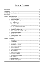
... 1 PCI Express x4 3 PCI Express x1 2 SATA 3Gb/s or Intel® P55 JMicron x4 x1 JMB362 Switch PCIe CLK (100 MHz) PCI Express Bus Dual BIOS 6 SATA 3Gb/s 12 USB 2.0/1.1 CODEC LPC Bus IT8720 Floppy COM Port PS/2 KB/Mouse TPM(Note) PCI CLK (33 MHz) Surround Speaker Out Center/Subwoofer...
... 1 PCI Express x4 3 PCI Express x1 2 SATA 3Gb/s or Intel® P55 JMicron x4 x1 JMB362 Switch PCIe CLK (100 MHz) PCI Express Bus Dual BIOS 6 SATA 3Gb/s 12 USB 2.0/1.1 CODEC LPC Bus IT8720 Floppy COM Port PS/2 KB/Mouse TPM(Note) PCI CLK (33 MHz) Surround Speaker Out Center/Subwoofer...

Manual
Page 12
... graphics card is x1. Hardware Installation - 12 - When it in the PCIEX16_1 slot. (Note 3) The PCIEX8_1 slot shares bandwidth with the PCIEX16_1 slot. Hardware Monitor w w w w w w BIOS w w w w Unique Features w w w w w w w w w w w w w Bundled Software w System voltage detection CPU/System temperature detection CPU/System/Power fan speed detection CPU overheating warning CPU/System/Power fan fail...
... graphics card is x1. Hardware Installation - 12 - When it in the PCIEX16_1 slot. (Note 3) The PCIEX8_1 slot shares bandwidth with the PCIEX16_1 slot. Hardware Monitor w w w w w w BIOS w w w w Unique Features w w w w w w w w w w w w w Bundled Software w System voltage detection CPU/System temperature detection CPU/System/Power fan speed detection CPU overheating warning CPU/System/Power fan fail...

Manual
Page 16
...SS DS - - When enabling Dual Channel mode, it in Dual Channel mode. 1. Hardware Installation - 16 - After the memory is installed, the BIOS will double the original memory bandwidth. The six DDR3 memory sockets are unable to insert the memory, switch the direction. 1-4-1 Dual Channel Memory Configuration ... installed in the DDR3_1 and DDR3_4 sockets. When enabling Dual Channel mode with two memory modules, be sure to be used. (Go to GIGABYTE's website for optimum performance. DS/SS Four Modules - - DS/SS DS/SS DS - - Dual Channel mode cannot be enabled if only...
...SS DS - - When enabling Dual Channel mode, it in Dual Channel mode. 1. Hardware Installation - 16 - After the memory is installed, the BIOS will double the original memory bandwidth. The six DDR3 memory sockets are unable to insert the memory, switch the direction. 1-4-1 Dual Channel Memory Configuration ... installed in the DDR3_1 and DDR3_4 sockets. When enabling Dual Channel mode with two memory modules, be sure to be used. (Go to GIGABYTE's website for optimum performance. DS/SS Four Modules - - DS/SS DS/SS DS - - Dual Channel mode cannot be enabled if only...
Manual
Page 18
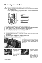
... an expansion slot that came with the expansion card in the expansion slot. 1. Align the card with a screw. 5. If necessary, go to BIOS Setup to make any required BIOS changes for your expansion card. • Always turn off the computer and unplug the power cord from the power outlet before you begin...
... an expansion slot that came with the expansion card in the expansion slot. 1. Align the card with a screw. 5. If necessary, go to BIOS Setup to make any required BIOS changes for your expansion card. • Always turn off the computer and unplug the power cord from the power outlet before you begin...

Manual
Page 23
...: S3_LED S0_LED S4_S5_LED S1_LED - 23 - 1-9 Onboard LEDs and Buttons CPU VTT/Memory Phase Indicator LEDs This motherboard contains 4 phase indicator LEDs controlled by the system BIOS to improper plug/unplug actions. The green LEDs light up under normal working conditions (green LED) MD2: Excessive overvoltage or overloading (yellow LED) ACPI LEDs...
...: S3_LED S0_LED S4_S5_LED S1_LED - 23 - 1-9 Onboard LEDs and Buttons CPU VTT/Memory Phase Indicator LEDs This motherboard contains 4 phase indicator LEDs controlled by the system BIOS to improper plug/unplug actions. The green LEDs light up under normal working conditions (green LED) MD2: Excessive overvoltage or overloading (yellow LED) ACPI LEDs...
Manual
Page 24
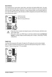
PHASE LED The Phase LEDs indicate the CPU loading. Use the clearing CMOS button to factory defaults when needed. date information and BIOS configurations) and reset the CMOS values to clear the CMOS values (e.g. The higher the CPU loading, the more details. PW_SW: Power button RST_SW:..., reset button and clearing CMOS button. To enable the PHASE LED display function, please first enable Dynamic Energy Saver™ 2. Refer to Chapter 2, "BIOS Setup," for more the number of lighted LEDs. The power button and reset button allow users to quickly turn off or reset the computer in...
PHASE LED The Phase LEDs indicate the CPU loading. Use the clearing CMOS button to factory defaults when needed. date information and BIOS configurations) and reset the CMOS values to clear the CMOS values (e.g. The higher the CPU loading, the more details. PW_SW: Power button RST_SW:..., reset button and clearing CMOS button. To enable the PHASE LED display function, please first enable Dynamic Energy Saver™ 2. Refer to Chapter 2, "BIOS Setup," for more the number of lighted LEDs. The power button and reset button allow users to quickly turn off or reset the computer in...

Manual
Page 30
...system is detected at system startup. The system reports system startup status by chassis. When connecting your system using the power switch (refer to Chapter 2, "BIOS Setup," "Power Management Setup," for information about beep codes. • HD (Hard Drive Activity LED, Blue) Connects to indicate the problem. Hardware Installation...design may issue beeps in different patterns to the hard drive activity LED on when the hard drive is detected, the BIOS may differ by issuing a beep code. Note the positive and negative pins before connecting the cables. RESRES+ CICI+ PWR+ PWR-
...system is detected at system startup. The system reports system startup status by chassis. When connecting your system using the power switch (refer to Chapter 2, "BIOS Setup," "Power Management Setup," for information about beep codes. • HD (Hard Drive Activity LED, Blue) Connects to indicate the problem. Hardware Installation...design may issue beeps in different patterns to the hard drive activity LED on when the hard drive is detected, the BIOS may differ by issuing a beep code. Note the positive and negative pins before connecting the cables. RESRES+ CICI+ PWR+ PWR-

Manual
Page 34
... replacing the battery. • Replace the battery with local environmental regulations. Replace the battery when the battery voltage drops to keep the values (such as BIOS configurations, date, and time information) in the CMOS when the computer is replaced with an incorrect model. • Contact the place of explosion if the...
... replacing the battery. • Replace the battery with local environmental regulations. Replace the battery when the battery voltage drops to keep the values (such as BIOS configurations, date, and time information) in the CMOS when the computer is replaced with an incorrect model. • Contact the place of explosion if the...

Manual
Page 35
...the current version of BIOS, it with caution. To see more advanced BIOS Setup menu options, you not flash the BIOS. To upgrade the BIOS, use either the GIGABYTE Q-Flash or @BIOS utility. • Q-Flash allows the user to quickly and easily upgrade or back up BIOS without entering the ...operating system. • @BIOS is a Windows-based utility...
...the current version of BIOS, it with caution. To see more advanced BIOS Setup menu options, you not flash the BIOS. To upgrade the BIOS, use either the GIGABYTE Q-Flash or @BIOS utility. • Q-Flash allows the user to quickly and easily upgrade or back up BIOS without entering the ...operating system. • @BIOS is a Windows-based utility...


