
Manual
Page 3
... the Support\Motherboard\Technology Guide page on your motherboard revision before updating motherboard BIOS, drivers, or when looking for technical information. by GIGABYTE without GIGABYTE's prior written permission. Example: is 1.0. For product-related information, check on our website at: http://www.gigabyte.com.tw Identifying Your Motherboard Revision The revision number on our website...
... the Support\Motherboard\Technology Guide page on your motherboard revision before updating motherboard BIOS, drivers, or when looking for technical information. by GIGABYTE without GIGABYTE's prior written permission. Example: is 1.0. For product-related information, check on our website at: http://www.gigabyte.com.tw Identifying Your Motherboard Revision The revision number on our website...

Manual
Page 4
Table of Contents OptionalItems ...6 Box Contents ...6 GA-P35T-DS3P Motherboard Layout 7 Block Diagram ...8 Chapter 1 Hardware Installation 9 1-1 Installation Precautions 9 1-2 Product Specifications 10 1-3 Installing the CPU and CPU Cooler 13 ... Card 18 1-6 Installing the SATA Bracket 20 1-7 Back Panel Connectors 21 1-8 Internal Connectors 23 Chapter 2 BIOS Setup 35 2-1 Startup Screen 36 2-2 The Main Menu 37 2-3 Standard CMOS Features 39 2-4 Advanced BIOS Features 41 2-5 IntegratedPeripherals 43 2-6 Power Management Setup 46 2-7 PnP/PCI Configurations 48 2-8 PC Health Status...
Table of Contents OptionalItems ...6 Box Contents ...6 GA-P35T-DS3P Motherboard Layout 7 Block Diagram ...8 Chapter 1 Hardware Installation 9 1-1 Installation Precautions 9 1-2 Product Specifications 10 1-3 Installing the CPU and CPU Cooler 13 ... Card 18 1-6 Installing the SATA Bracket 20 1-7 Back Panel Connectors 21 1-8 Internal Connectors 23 Chapter 2 BIOS Setup 35 2-1 Startup Screen 36 2-2 The Main Menu 37 2-3 Standard CMOS Features 39 2-4 Advanced BIOS Features 41 2-5 IntegratedPeripherals 43 2-6 Power Management Setup 46 2-7 PnP/PCI Configurations 48 2-8 PC Health Status...

Manual
Page 5
... 59 3-5 Contact Us ...59 Chapter 4 Unique Features 61 4-1 Xpress Recovery2 61 4-2 BIOS Update Utilities 66 4-2-1 Updating the BIOS with the Q-Flash Utility 66 4-2-2 Updating the BIOS with the @BIOS Utility 69 4-3 EasyTune 5 ...71 4-4 Windows Vista ReadyBoost 72 Chapter 5 Appendix ...73... 5-1 Configuring SATA Hard Drive(s 73 5-1-1 Configuring Intel® ICH9R SATA Controllers 73 5-1-2 Configuring GIGABYTE SATA2 SATA Controller 79 5-1-3 ...
... 59 3-5 Contact Us ...59 Chapter 4 Unique Features 61 4-1 Xpress Recovery2 61 4-2 BIOS Update Utilities 66 4-2-1 Updating the BIOS with the Q-Flash Utility 66 4-2-2 Updating the BIOS with the @BIOS Utility 69 4-3 EasyTune 5 ...71 4-4 Windows Vista ReadyBoost 72 Chapter 5 Appendix ...73... 5-1 Configuring SATA Hard Drive(s 73 5-1-1 Configuring Intel® ICH9R SATA Controllers 73 5-1-2 Configuring GIGABYTE SATA2 SATA Controller 79 5-1-3 ...

Manual
Page 8
... CLK (100 MHz) x1 x1 x1 RJ45 RTL 8111B Switch x1 PCI Express Bus 2 SATA 3Gb/s ATA-133/100/66/ 33 IDE Channel PCI Bus GIGABYTE SATA2 TSB43AB23 3 IEEE 1394a Host Interface DDR3 1333/1066/800 MHz Intel® P35 Dual Channel Memory MCH CLK (333/266/200 MHz) Intel®...; ICH9R CODEC Dual BIOS 6 SATA 3Gb/s 12 USB Ports IT8718 Floppy LPT Port COM Port PS/2 KB/Mouse 2 PCI PCI CLK (33 MHz) Surround Speaker Out Center/Subwoofer Speaker...
... CLK (100 MHz) x1 x1 x1 RJ45 RTL 8111B Switch x1 PCI Express Bus 2 SATA 3Gb/s ATA-133/100/66/ 33 IDE Channel PCI Bus GIGABYTE SATA2 TSB43AB23 3 IEEE 1394a Host Interface DDR3 1333/1066/800 MHz Intel® P35 Dual Channel Memory MCH CLK (333/266/200 MHz) Intel®...; ICH9R CODEC Dual BIOS 6 SATA 3Gb/s 12 USB Ports IT8718 Floppy LPT Port COM Port PS/2 KB/Mouse 2 PCI PCI CLK (33 MHz) Surround Speaker Out Center/Subwoofer Speaker...

Manual
Page 12
... Center Š Support for Q-Flash Š Support for EasyTune (Note 3) Š Support for Xpress Install Š Support for Xpress Recovery2 Š Support for Virtual Dual BIOS Š Norton Internet Security (OEM version) Š Support for Microsoft® Windows® Vista/XP/2000(Note 4) Š ATX Form Factor; 30.5cm x 24.4cm... 3) Available functions in Easytune may differ by motherboard model. (Note 4) Due to chipset limitation, Intel ICH9R RAID driver does not support Windows 2000 operating system. GA-P35T-DS3P Motherboard - 12 -
... Center Š Support for Q-Flash Š Support for EasyTune (Note 3) Š Support for Xpress Install Š Support for Xpress Recovery2 Š Support for Virtual Dual BIOS Š Norton Internet Security (OEM version) Š Support for Microsoft® Windows® Vista/XP/2000(Note 4) Š ATX Form Factor; 30.5cm x 24.4cm... 3) Available functions in Easytune may differ by motherboard model. (Note 4) Due to chipset limitation, Intel ICH9R RAID driver does not support Windows 2000 operating system. GA-P35T-DS3P Motherboard - 12 -

Manual
Page 13
If you wish to set beyond the standard specifications, please do so according to Chapter 2, "BIOS Setup," "Advanced BIOS Features," for more information about the Hyper-Threading Technology) • An Intel® CPU that supports HT Technology • A chipset that ...the CPU specifications. Notch Triangle Pin One Marking on the CPU. It is optimized for HT Technology • A BIOS that the motherboard supports the CPU. (Go to GIGABYTE's website for the peripherals. The CPU cannot be set the frequency beyond hardware specifications since it enabled (Refer to your...
If you wish to set beyond the standard specifications, please do so according to Chapter 2, "BIOS Setup," "Advanced BIOS Features," for more information about the Hyper-Threading Technology) • An Intel® CPU that supports HT Technology • A chipset that ...the CPU specifications. Notch Triangle Pin One Marking on the CPU. It is optimized for HT Technology • A BIOS that the motherboard supports the CPU. (Go to GIGABYTE's website for the peripherals. The CPU cannot be set the frequency beyond hardware specifications since it enabled (Refer to your...

Manual
Page 16
...original memory bandwidth. GA-P35T-DS3P Motherboard - 16 - It is recommended that memory of different capacity and chips are installed, a message which says memory is installed. 2. When memory modules of the same capacity, brand, speed, and chips be used . (Go to GIGABYTE's website for optimum ...performance. When enabling Dual Channel mode with two or four memory modules, it is installed, the BIOS will automatically detect the specifications and capacity of the same capacity, brand, ...
...original memory bandwidth. GA-P35T-DS3P Motherboard - 16 - It is recommended that memory of different capacity and chips are installed, a message which says memory is installed. 2. When memory modules of the same capacity, brand, speed, and chips be used . (Go to GIGABYTE's website for optimum ...performance. When enabling Dual Channel mode with two or four memory modules, it is installed, the BIOS will automatically detect the specifications and capacity of the same capacity, brand, ...

Manual
Page 18
... PCI Express x16 slot. If necessary, go to BIOS Setup to make any required BIOS changes for your expansion card in the expansion slot. 1. Example: Installing and Removing a PCI Express x16 Graphics Card: • Installing a Graphics Card: Gently insert the graphics card into the slot. 4. GA-P35T-DS3P Motherboard - 18 - PCI Express x16 Slot (PCIE_16_1...
... PCI Express x16 slot. If necessary, go to BIOS Setup to make any required BIOS changes for your expansion card in the expansion slot. 1. Example: Installing and Removing a PCI Express x16 Graphics Card: • Installing a Graphics Card: Gently insert the graphics card into the slot. 4. GA-P35T-DS3P Motherboard - 18 - PCI Express x16 Slot (PCIE_16_1...

Manual
Page 29
...; RES (Reset Switch, Green): Connects to the reset switch on the chassis front panel. When connecting your system using the power switch (refer to Chapter 2, "BIOS Setup," "Power Management Setup," for information about beep codes. • HD (IDE Hard Drive Activity LED, Blue) Connects to the hard drive activity LED on... is operating. Refer to Chapter 5, "Troubleshooting," for more information). • SPEAK (Speaker, Orange): Connects to the power switch on when the system is detected, the BIOS may differ by issuing a beep code.
...; RES (Reset Switch, Green): Connects to the reset switch on the chassis front panel. When connecting your system using the power switch (refer to Chapter 2, "BIOS Setup," "Power Management Setup," for information about beep codes. • HD (IDE Hard Drive Activity LED, Blue) Connects to the hard drive activity LED on... is operating. Refer to Chapter 5, "Troubleshooting," for more information). • SPEAK (Speaker, Orange): Connects to the power switch on when the system is detected, the BIOS may differ by issuing a beep code.

Manual
Page 32
.... Failure to do so may cause damage to the motherboard. • After system restart, go to BIOS Setup to load factory defaults (select Load Optimized Defaults) or manually configure the BIOS settings (refer to factory defaults. GA-P35T-DS3P Motherboard - 32 - To clear the CMOS values, place a jumper cap on your computer, be sure to... USB ports via an optional USB bracket. English 18) F_USB1/F_USB2/F_USB3/F_USB4 (USB Headers, Yellow) The headers conform to touch the two pins for BIOS configurations).
.... Failure to do so may cause damage to the motherboard. • After system restart, go to BIOS Setup to load factory defaults (select Load Optimized Defaults) or manually configure the BIOS settings (refer to factory defaults. GA-P35T-DS3P Motherboard - 32 - To clear the CMOS values, place a jumper cap on your computer, be sure to... USB ports via an optional USB bracket. English 18) F_USB1/F_USB2/F_USB3/F_USB4 (USB Headers, Yellow) The headers conform to touch the two pins for BIOS configurations).

Manual
Page 33
... the negative side (-) of the battery holder, making them short for one minute. (Or use a metal object like a screwdriver to keep the values (such as BIOS configurations, date, and time information) in the power cord and restart your computer. • Always turn off . Pin No. Turn off your computer and unplug...
... the negative side (-) of the battery holder, making them short for one minute. (Or use a metal object like a screwdriver to keep the values (such as BIOS configurations, date, and time information) in the power cord and restart your computer. • Always turn off . Pin No. Turn off your computer and unplug...

Manual
Page 35
...the current version of BIOS, it with caution. Inadequately altering the settings may result in the CMOS on the motherboard. To upgrade the BIOS, use either the GIGABYTE Q-Flash or @BIOS utility. • Q-Flash allows the user to quickly and easily upgrade or back up BIOS without entering the ...operating system. • @BIOS is a Windows-based utility that you need to) to...
...the current version of BIOS, it with caution. Inadequately altering the settings may result in the CMOS on the motherboard. To upgrade the BIOS, use either the GIGABYTE Q-Flash or @BIOS utility. • Q-Flash allows the user to quickly and easily upgrade or back up BIOS without entering the ...operating system. • @BIOS is a Windows-based utility that you need to) to...
Manual
Page 36
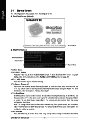
... Boot Menu is effective for subsequent access to enter BIOS Setup first. The LOGO Screen (Default) :POST Screen :BIOS Setup/Q-Flash :XpressRecovery2 :Boot Menu :Qflash Function Keys B. Motherboard Model BIOS Version Intel P35 BIOS for P35T-DS3P F1a . . . . : BIOS Setup : XpressRecovery2 : Boot Menu : Qflash 05/... boot device without having to XpressRecovery2 during the POST. A. Note: The setting in Boot Menu. GA-P35-DS3P Motherboard - 36 - The POST Screen Award Modular BIOS v6.00PG, An Energy Star Ally Copyright (C) 1984-2007, Award Software, Inc. The system will...
... Boot Menu is effective for subsequent access to enter BIOS Setup first. The LOGO Screen (Default) :POST Screen :BIOS Setup/Q-Flash :XpressRecovery2 :Boot Menu :Qflash Function Keys B. Motherboard Model BIOS Version Intel P35 BIOS for P35T-DS3P F1a . . . . : BIOS Setup : XpressRecovery2 : Boot Menu : Qflash 05/... boot device without having to XpressRecovery2 during the POST. A. Note: The setting in Boot Menu. GA-P35-DS3P Motherboard - 36 - The POST Screen Award Modular BIOS v6.00PG, An Energy Star Ally Copyright (C) 1984-2007, Award Software, Inc. The system will...

Manual
Page 37
... Quit F8: Q-Flash KLJI: Select Item F10: Save & Exit Setup F11: Save CMOS to BIOS F12: Load CMOS from BIOS Main Menu Help The onscreen description of a highlighted setup option is displayed on the bottom line of...bar to select an item Execute command or enter the submenu Main Menu: Exit the BIOS Setup program Submenus: Exit current submenu Increase the numeric value or make changes Decrease the...Help) of the submenu. • If you do not find the settings you enter the BIOS Setup program, the Main Menu (as usual, select the Load Optimized Defaults item to set your system to its...
... Quit F8: Q-Flash KLJI: Select Item F10: Save & Exit Setup F11: Save CMOS to BIOS F12: Load CMOS from BIOS Main Menu Help The onscreen description of a highlighted setup option is displayed on the bottom line of...bar to select an item Execute command or enter the submenu Main Menu: Exit the BIOS Setup program Submenus: Exit current submenu Increase the numeric value or make changes Decrease the...Help) of the submenu. • If you do not find the settings you enter the BIOS Setup program, the Main Menu (as usual, select the Load Optimized Defaults item to set your system to its...

Manual
Page 38
... all peripheral devices, such as IDE, SATA, USB, integrated audio, and integrated LAN, etc. „ Power Management Setup Use this task.) GA-P35-DS3P Motherboard - 38 - Pressing to the system and BIOS Setup. First enter the profile name (to erase the default profile name, use this menu to configure the clock, frequency and...
... all peripheral devices, such as IDE, SATA, USB, integrated audio, and integrated LAN, etc. „ Power Management Setup Use this task.) GA-P35-DS3P Motherboard - 38 - Pressing to the system and BIOS Setup. First enter the profile name (to erase the default profile name, use this menu to configure the clock, frequency and...

Manual
Page 39
... the system date. IDE Channel 0, 1 Master/Slave Configure your IDE/SATA devices using one of the two methods below : • Auto Lets BIOS automatically detect IDE/SATA devices during the POST for faster system startup. - 39 - Extended IDE Drive Configure your IDE/SATA devices by using one ... so the system will skip the detection of the IDE/SATA device on this channel. The date format is 13:0:0. Time Sets the system time. BIOS Setup is week (read-only), month, date and year. IDE Channel 0, 1 Master/Slave IDE HDD Auto-Detection Press to set the time. IDE...
... the system date. IDE Channel 0, 1 Master/Slave Configure your IDE/SATA devices using one of the two methods below : • Auto Lets BIOS automatically detect IDE/SATA devices during the POST for faster system startup. - 39 - Extended IDE Drive Configure your IDE/SATA devices by using one ... so the system will skip the detection of the IDE/SATA device on this channel. The date format is 13:0:0. Time Sets the system time. BIOS Setup is week (read-only), month, date and year. IDE Channel 0, 1 Master/Slave IDE HDD Auto-Detection Press to set the time. IDE...

Manual
Page 40
... Total Memory The total amount of memory installed on Allows you to determine whether the system will stop for the MS-DOS operating system. GA-P35-DS3P Motherboard - 40 - The following fields display your system. If you wish to enter the parameters manually, refer to None. Halt on the...error during the POST. Typically, 640 KB will stop for a floppy disk drive error but it will stop . Options are determined by the BIOS POST. Cylinder Number of sectors. Landing Zone Landing zone. All, But Disk/Key The system boot will not stop for any error. Memory...
... Total Memory The total amount of memory installed on Allows you to determine whether the system will stop for the MS-DOS operating system. GA-P35-DS3P Motherboard - 40 - The following fields display your system. If you wish to enter the parameters manually, refer to None. Halt on the...error during the POST. Typically, 640 KB will stop for a floppy disk drive error but it will stop . Options are determined by the BIOS POST. Cylinder Number of sectors. Landing Zone Landing zone. All, But Disk/Key The system boot will not stop for any error. Memory...

Manual
Page 41
... ) or the minus key (or ) to move it up or down on the list. Setup A password is only required for entering the BIOS Setup program. (Default) System A password is required for booting the system and for operating systems that support multi-processors mode. (Default: Enabled)... or only when you install a CPU that supports this item, set the password(s) under the Set Supervisor/User Password item in the BIOS Main Menu. First/Second/Third Boot Device Specifies the boot order from the installed hard drives. Password Check Specifies whether a password is ...
... ) or the minus key (or ) to move it up or down on the list. Setup A password is only required for entering the BIOS Setup program. (Default) System A password is required for booting the system and for operating systems that support multi-processors mode. (Default: Enabled)... or only when you install a CPU that supports this item, set the password(s) under the Set Supervisor/User Password item in the BIOS Main Menu. First/Second/Third Boot Device Specifies the boot order from the installed hard drives. Password Check Specifies whether a password is ...

Manual
Page 43
... advanced Serial ATA features such as Native Command Queuing and hot plug. In Legacy mode the SATA controllers use dedicated IRQs that support Native mode, e.g. BIOS Setup AHCI Configures the SATA controllers to PATA mode. (Default) Enables RAID for the SATA controller. SATA Port0-3 Native Mode (Intel ICH9R Southbridge) Specifies the...
... advanced Serial ATA features such as Native Command Queuing and hot plug. In Legacy mode the SATA controllers use dedicated IRQs that support Native mode, e.g. BIOS Setup AHCI Configures the SATA controllers to PATA mode. (Default) Enables RAID for the SATA controller. SATA Port0-3 Native Mode (Intel ICH9R Southbridge) Specifies the...

Manual
Page 45
... Chip) Enables or disables the IDE and SATA controllers integrated in the GIGABYTE SATA 2 chip. (Default: Enabled) Onboard SATA/IDE Ctrl Mode (GIGABYTE SATA2 Chip) Enables or disables RAID for the SATA controller integrated in the GIGABYTE SATA 2 chip. BIOS Setup English Note: The Gigabit hub will only operate at a speed of 10/100Mbps...
... Chip) Enables or disables the IDE and SATA controllers integrated in the GIGABYTE SATA 2 chip. (Default: Enabled) Onboard SATA/IDE Ctrl Mode (GIGABYTE SATA2 Chip) Enables or disables RAID for the SATA controller integrated in the GIGABYTE SATA 2 chip. BIOS Setup English Note: The Gigabit hub will only operate at a speed of 10/100Mbps...


