
Manual
Page 4
Table of Contents ItemChecklist ...6 OptionalAccessories ...6 GA-N650SLI-DS4 Motherboard Layout 7 Block Diagram ...8 Chapter 1 Hardware Installation 9 1-1 Considerations Prior to Installation 9 1-2 Feature Summary 10 1-3 Installation of the ... (Scalable Link Interface) Configuration 17 1-7 I/O Back Panel Introduction 20 1-8 Connectors Introduction 21 Chapter 2 BIOS Setup 33 The Main Menu (For example: BIOS Ver. : F1a 35 2-1 Standard CMOS Features 37 2-2 Advanced BIOS Features 39 2-3 IntegratedPeripherals 41 2-4 Power Management Setup 45 2-5 PnP/PCI Configurations 47 2-6 PC Health ...
Table of Contents ItemChecklist ...6 OptionalAccessories ...6 GA-N650SLI-DS4 Motherboard Layout 7 Block Diagram ...8 Chapter 1 Hardware Installation 9 1-1 Considerations Prior to Installation 9 1-2 Feature Summary 10 1-3 Installation of the ... (Scalable Link Interface) Configuration 17 1-7 I/O Back Panel Introduction 20 1-8 Connectors Introduction 21 Chapter 2 BIOS Setup 33 The Main Menu (For example: BIOS Ver. : F1a 35 2-1 Standard CMOS Features 37 2-2 Advanced BIOS Features 39 2-3 IntegratedPeripherals 41 2-4 Power Management Setup 45 2-5 PnP/PCI Configurations 47 2-6 PC Health ...

Manual
Page 5
Chapter 3 Drivers Installation 57 3-1 Install Chipset Drivers 57 3-2 SoftwareApplications 58 3-3 Driver CD Information 58 3-4 Hardware Information 59 3-5 Contact Us ...59 3-6 Windows Vista ReadyBoost 60 Chapter 4 Appendix 61 4-1 Unique Software Utilities 61 4-1-1 EasyTune 5 Introduction 61 4-1-2 Xpress Recovery2 Introduction 62 4-1-3 Flash BIOS Method Introduction 64 4-1-4 Configuring SATA Hard Drive(s 71 4-1-5 2- / 4- / 6- / 8- Channel Audio Function Introduction 81 4-2 Troubleshooting 86 - 5 -
Chapter 3 Drivers Installation 57 3-1 Install Chipset Drivers 57 3-2 SoftwareApplications 58 3-3 Driver CD Information 58 3-4 Hardware Information 59 3-5 Contact Us ...59 3-6 Windows Vista ReadyBoost 60 Chapter 4 Appendix 61 4-1 Unique Software Utilities 61 4-1-1 EasyTune 5 Introduction 61 4-1-2 Xpress Recovery2 Introduction 62 4-1-3 Flash BIOS Method Introduction 64 4-1-4 Configuring SATA Hard Drive(s 71 4-1-5 2- / 4- / 6- / 8- Channel Audio Function Introduction 81 4-2 Troubleshooting 86 - 5 -

Manual
Page 8
... LAN RJ45 Marvell 88E1116 2 PCI Express x 1 PCI Bus TSB43AB23 nVIDIA® nForce 650i SLI Southbridge 4 SATA 3Gb/s ATA 33/66/100/133 IDE Channels Dual BIOS LPC BUS IT8718 Floppy LPT Port CODEC COM Port 8 USB Ports PS/2 KB/Mouse 3 IEEE 1394a Surround Speaker Out Center/Subwoofer Speaker Out Side Speaker...
... LAN RJ45 Marvell 88E1116 2 PCI Express x 1 PCI Bus TSB43AB23 nVIDIA® nForce 650i SLI Southbridge 4 SATA 3Gb/s ATA 33/66/100/133 IDE Channels Dual BIOS LPC BUS IT8718 Floppy LPT Port CODEC COM Port 8 USB Ports PS/2 KB/Mouse 3 IEEE 1394a Surround Speaker Out Center/Subwoofer Speaker Out Side Speaker...

Manual
Page 11
...System/Power fan failure warning Š CPU/System Smart Fan Control BIOS Š 2 4 Mbit flash ROM Š Use of licensed AWARD BIOS Š Supports Dual BIOS Š PnP 1.0a, DMI 2.0, SM BIOS 2.3, ACPI 1.0b Additional Features Š Supports @BIOS Š Supports Download Center Š Supports Q-Flash Š... Supports EasyTune (Note 3) Š Supports Xpress Install Š Supports Xpress Recovery2 Š Supports Xpress BIOS Rescue Bundle Software Š Norton Internet Security (OEM revision) Form Factor Š ATX form factor; 30.5cm x 24.4cm ...
...System/Power fan failure warning Š CPU/System Smart Fan Control BIOS Š 2 4 Mbit flash ROM Š Use of licensed AWARD BIOS Š Supports Dual BIOS Š PnP 1.0a, DMI 2.0, SM BIOS 2.3, ACPI 1.0b Additional Features Š Supports @BIOS Š Supports Download Center Š Supports Q-Flash Š... Supports EasyTune (Note 3) Š Supports Xpress Install Š Supports Xpress Recovery2 Š Supports Xpress BIOS Rescue Bundle Software Š Norton Internet Security (OEM revision) Form Factor Š ATX form factor; 30.5cm x 24.4cm ...

Manual
Page 12
...on the edge of the CPU socket. Please make sure the CPU cooler is installed on the CPU socket to the CPU during installation.) GA-N650SLI-DS4 Motherboard - 12 - It is properly inserted, please replace the load plate and push the metal lever back into the socket in the ...wrong direction, the CPU will not insert properly. Fig. 4 Once the CPU is not recommended that the motherboard supports the CPU. 2. BIOS: A BIOS that has optimizations for your hardware specifications including the CPU, graphics card, memory, hard drive, etc. If you install the CPU in a straight...
...on the edge of the CPU socket. Please make sure the CPU cooler is installed on the CPU socket to the CPU during installation.) GA-N650SLI-DS4 Motherboard - 12 - It is properly inserted, please replace the load plate and push the metal lever back into the socket in the ...wrong direction, the CPU will not insert properly. Fig. 4 Once the CPU is not recommended that the motherboard supports the CPU. 2. BIOS: A BIOS that has optimizations for your hardware specifications including the CPU, graphics card, memory, hard drive, etc. If you install the CPU in a straight...

Manual
Page 14
...it down. Notch DDRII Fig.1 The DIMM socket has a notch, so the DIMM memory module can be inserted only in one direction. GA-N650SLI-DS4 Motherboard - 14 - English 1-4 Installation of Memory Before installing the memory modules, please comply with each slot. Memory modules have a ...foolproof insertion design. The motherboard supports DDRII memory modules, whereby BIOS will automatically detect memory capacity and specifications. It is switched off to insert the module, please switch the direction. A memory ...
...it down. Notch DDRII Fig.1 The DIMM socket has a notch, so the DIMM memory module can be inserted only in one direction. GA-N650SLI-DS4 Motherboard - 14 - English 1-4 Installation of Memory Before installing the memory modules, please comply with each slot. Memory modules have a ...foolproof insertion design. The motherboard supports DDRII memory modules, whereby BIOS will automatically detect memory capacity and specifications. It is switched off to insert the module, please switch the direction. A memory ...

Manual
Page 16
... you try to the onboard PCI Express x16 slot and press firmly down on the computer, if necessary, setup BIOS utility of expansion card from BIOS. 8. Read the related expansion card's instruction document before install the expansion card into expansion slot in the slot..... Make sure your computer's chassis cover. 7. Press the expansion card firmly into the computer. 2. Install related driver from the computer. 3. GA-N650SLI-DS4 Motherboard - 16 - English 1-5 Installation of Expansion Cards You can also press the latch on the card are indeed seated in motherboard. 4. ...
... you try to the onboard PCI Express x16 slot and press firmly down on the computer, if necessary, setup BIOS utility of expansion card from BIOS. 8. Read the related expansion card's instruction document before install the expansion card into expansion slot in the slot..... Make sure your computer's chassis cover. 7. Press the expansion card firmly into the computer. 2. Install related driver from the computer. 3. GA-N650SLI-DS4 Motherboard - 16 - English 1-5 Installation of Expansion Cards You can also press the latch on the card are indeed seated in motherboard. 4. ...
Manual
Page 19
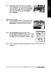
... slot, make sure to PEG(Slot2). Step 2: Select SLI multi-GPU from the side menu and then select the Enable SLI multi-GPU checkbox in BIOS Setup to the user's manual for your system tray and then select NVIDIA Display. Hardware Installation Then the SLI configuration is completed. (Note) For more...
... slot, make sure to PEG(Slot2). Step 2: Select SLI multi-GPU from the side menu and then select the Enable SLI multi-GPU checkbox in BIOS Setup to the user's manual for your system tray and then select NVIDIA Display. Hardware Installation Then the SLI configuration is completed. (Note) For more...

Manual
Page 25
Please refer to the BIOS setting for information on one IDE cable, and the single IDE cable can provide up to two IDE devices (hard drive or optical drive). If ...
Please refer to the BIOS setting for information on one IDE cable, and the single IDE cable can provide up to two IDE devices (hard drive or optical drive). If ...

Manual
Page 30
... or even damage it. You can check the "Case Opened" status in BIOS Setup. Pin No. Be careful with the polarity of Electrical and Electronics Engineers, which has features like high speed, highbandwidth and hot plug. Definition 1 Signal 1 2 GND GA-N650SLI-DS4 Motherboard - 30 - Check the pin assignment carefully while you connect the IEEE...
... or even damage it. You can check the "Case Opened" status in BIOS Setup. Pin No. Be careful with the polarity of Electrical and Electronics Engineers, which has features like high speed, highbandwidth and hot plug. Definition 1 Signal 1 2 GND GA-N650SLI-DS4 Motherboard - 30 - Check the pin assignment carefully while you connect the IEEE...

Manual
Page 33
...boot to a new BIOS, either Gigabyte's Q-Flash or @BIOS utility can enter the BIOS setup screen by pressing "Ctrl + F1". Q-Flash allows the user to quickly and easily update or backup BIOS without entering the operating system. @BIOS is turned on, pressing the button during the BIOS POST (Power-On ...and Option Page Setup Menu - Status Page Setup Menu / Option Page Setup Menu Press F1 to the CMOS SRAM. English Chapter 2 BIOS Setup BIOS (Basic Input and Output System) includes a CMOS SETUP utility which allows user to configure required settings or to select item Select Item...
...boot to a new BIOS, either Gigabyte's Q-Flash or @BIOS utility can enter the BIOS setup screen by pressing "Ctrl + F1". Q-Flash allows the user to quickly and easily update or backup BIOS without entering the operating system. @BIOS is turned on, pressing the button during the BIOS POST (Power-On ...and Option Page Setup Menu - Status Page Setup Menu / Option Page Setup Menu Press F1 to the CMOS SRAM. English Chapter 2 BIOS Setup BIOS (Basic Input and Output System) includes a CMOS SETUP utility which allows user to configure required settings or to select item Select Item...

Manual
Page 34
...GA-N650SLI-DS4 Motherboard - 34 - English Startup Screen: :POST Screen :BIOS Setup/Dual BIOS :XpressRecovery2 :Boot Menu : Qflash : POST Screen Press the TAB key to see BIOS POST screen. (To show the BIOS POST screen at system startup, refer to the instructions on the Full Screen LOGO Show item on page 40.) : BIOS Setup/Dual BIOS... Press the DELETE key to enter BIOS Setup program. : Xpress Recovery2 Press the F9 key to enter the Xpress Recovery2 screen. : Boot Menu ...
...GA-N650SLI-DS4 Motherboard - 34 - English Startup Screen: :POST Screen :BIOS Setup/Dual BIOS :XpressRecovery2 :Boot Menu : Qflash : POST Screen Press the TAB key to see BIOS POST screen. (To show the BIOS POST screen at system startup, refer to the instructions on the Full Screen LOGO Show item on page 40.) : BIOS Setup/Dual BIOS... Press the DELETE key to enter BIOS Setup program. : Xpress Recovery2 Press the F9 key to enter the Xpress Recovery2 screen. : Boot Menu ...

Manual
Page 35
...page is not stable as figure below) will appear on the screen. Select the Load Optimized Defaults item in standard compatible BIOS. „ Advanced BIOS Features This setup page includes all the items of Award special enhanced features. „ Integrated Peripherals This setup page includes ...MB Intelligent Tweaker(M.I.T.) Load Fail-Safe Defaults Load Optimized Defaults Set Supervisor Password Set User Password Save & Exit Setup Exit Without Saving F8: Dual BIOS/Q-Flash : Select Item F10: Save & Exit Setup Time, Date, Hard Disk Type... 1. F12 : Load CMOS from the exact settings for...
...page is not stable as figure below) will appear on the screen. Select the Load Optimized Defaults item in standard compatible BIOS. „ Advanced BIOS Features This setup page includes all the items of Award special enhanced features. „ Integrated Peripherals This setup page includes ...MB Intelligent Tweaker(M.I.T.) Load Fail-Safe Defaults Load Optimized Defaults Set Supervisor Password Set User Password Save & Exit Setup Exit Without Saving F8: Dual BIOS/Q-Flash : Select Item F10: Save & Exit Setup Time, Date, Hard Disk Type... 1. F12 : Load CMOS from the exact settings for...

Manual
Page 37
...this option for the hard drive. Access Mode Use this option for faster system start up . • Manual User can manually input the correct settings. BIOS Setup The four options are: CHS/LBA/Large/Auto(default:Auto) IDE Channel 2/3/4/5 Master IDE HDD Auto-Detection Press "Enter" to select this to ... device detection. Week The week, from Sun to 31 (or the maximum allowed in the month) Year The year, from 1 to Sat, determined by the BIOS and is calculated base on the 24-hour military- is , , , . English 2-1 Standard CMOS Features Date (mm:dd:yy) Time (hh:mm:ss) CMOS ...
...this option for the hard drive. Access Mode Use this option for faster system start up . • Manual User can manually input the correct settings. BIOS Setup The four options are: CHS/LBA/Large/Auto(default:Auto) IDE Channel 2/3/4/5 Master IDE HDD Auto-Detection Press "Enter" to select this to ... device detection. Week The week, from Sun to 31 (or the maximum allowed in the month) Year The year, from 1 to Sat, determined by the BIOS and is calculated base on the 24-hour military- is , , , . English 2-1 Standard CMOS Features Date (mm:dd:yy) Time (hh:mm:ss) CMOS ...

Manual
Page 38
...Floppy Drive. (Default value) Drive A is the amount of memory located above 1 MB in the system. GA-N650SLI-DS4 Motherboard - 38 - it will determine the amount of the BIOS. Base Memory The POST of the BIOS will stop for a disk error; Floppy 3 Mode Support (for systems with 640 K or more memory ...Errors The system boot will not stop for a keyboard error; All, But Keyboard The system boot will be stopped. Extended Memory The BIOS determines how much extended memory is detected during the POST. All, But Disk/Key The system boot will not stop for any error that...
...Floppy Drive. (Default value) Drive A is the amount of memory located above 1 MB in the system. GA-N650SLI-DS4 Motherboard - 38 - it will determine the amount of the BIOS. Base Memory The POST of the BIOS will stop for a disk error; Floppy 3 Mode Support (for systems with 640 K or more memory ...Errors The system boot will not stop for a keyboard error; All, But Keyboard The system boot will be stopped. Extended Memory The BIOS determines how much extended memory is detected during the POST. All, But Disk/Key The system boot will not stop for any error that...

Manual
Page 39
..., or to Setup page if the correct password is installed. Capability This feature allows your boot device priority by USB-FDD. capability. BIOS Setup capability. (Default value) (Note) This item will not access to move it up when you install a processor that supports this ...CPUID Max. Hard Disk Select your boot device priority by Legacy LAN. HDD S.M.A.R.T. English 2-2 Advanced BIOS Features CMOS Setup Utility-Copyright (C) 1984-2007 Award Software Advanced BIOS Features Hard Disk Boot Priority First Boot Device Second Boot Device Third Boot Device Password Check HDD ...
..., or to Setup page if the correct password is installed. Capability This feature allows your boot device priority by USB-FDD. capability. BIOS Setup capability. (Default value) (Note) This item will not access to move it up when you install a processor that supports this ...CPUID Max. Hard Disk Select your boot device priority by Legacy LAN. HDD S.M.A.R.T. English 2-2 Advanced BIOS Features CMOS Setup Utility-Copyright (C) 1984-2007 Award Software Advanced BIOS Features Hard Disk Boot Priority First Boot Device Second Boot Device Third Boot Device Password Check HDD ...

Manual
Page 40
... 3 (Note) Enabled Limit CPUID Maximum value to PCI Express VGA card (the PCIE_16_2 slot). (Note) This item will show up when you wish to see BIOS POST screen, set to "Disabled". CPU Thermal Monitor 2 (TM2) (Note) Enabled Enable CPU Thermal Monitor 2 (TM2) function. (Default value) Disabled Disable CPU Thermal ...initiation of the monitor display from which card when you to get higher performance. PCI Set Init Display First to PCI VGA card. GA-N650SLI-DS4 Motherboard - 40 - English CPU Hyper-Threading (Note) Enabled Enable CPU Hyper Threading Feature. function.
... 3 (Note) Enabled Limit CPUID Maximum value to PCI Express VGA card (the PCIE_16_2 slot). (Note) This item will show up when you wish to see BIOS POST screen, set to "Disabled". CPU Thermal Monitor 2 (TM2) (Note) Enabled Enable CPU Thermal Monitor 2 (TM2) function. (Default value) Disabled Disable CPU Thermal ...initiation of the monitor display from which card when you to get higher performance. PCI Set Init Display First to PCI VGA card. GA-N650SLI-DS4 Motherboard - 40 - English CPU Hyper-Threading (Note) Enabled Enable CPU Hyper Threading Feature. function.

Manual
Page 41
.... - 41 - SATA-II 1 Secondary RAID Enabled Enable RAID function for the first channel of the first SATA 3Gb/s controller. (Default value) Disabled Disable this function. BIOS Setup English 2-3 Integrated Peripherals CMOS Setup Utility-Copyright (C) 1984-2007 Award Software Integrated Peripherals SATA-II RAID Config On-Chip IDE Channel0 IDE DMA transfer...
.... - 41 - SATA-II 1 Secondary RAID Enabled Enable RAID function for the first channel of the first SATA 3Gb/s controller. (Default value) Disabled Disable this function. BIOS Setup English 2-3 Integrated Peripherals CMOS Setup Utility-Copyright (C) 1984-2007 Award Software Integrated Peripherals SATA-II RAID Config On-Chip IDE Channel0 IDE DMA transfer...

Manual
Page 43
... cable. When No LAN Cable Is Attached... When a Cable Problem Occurs... If a cable problem occurs on the LAN cable connected to the fault or short. BIOS Setup If no LAN cable is detected on a specified pair of the attached LAN cable. However, because Pair 4-5 and Pair 7-8 are not used in the...
... cable. When No LAN Cable Is Attached... When a Cable Problem Occurs... If a cable problem occurs on the LAN cable connected to the fault or short. BIOS Setup If no LAN cable is detected on a specified pair of the attached LAN cable. However, because Pair 4-5 and Pair 7-8 are not used in the...

Manual
Page 44
Onboard Serial Port 1 Auto 3F8/IRQ4 BIOS will scan all USB storage devices. (Default value) Disabled Disable this function. ECP Using Parallel port as ECP & EPP mode. GA-N650SLI-DS4 Motherboard - 44 - Enable onboard Serial port 1 and address is 3F8/IRQ4. (Default value) 2F8/IRQ3 ...as Extended Capabilities Port. English Onboard 1394 Enabled Enable onboard IEEE 1394 function. (Default value) Disabled Disable this function. Enabled BIOS will automatically setup the port 1 address. Parallel Port Mode SPP Using Parallel port as Standard Parallel Port. (Default value) ...
Onboard Serial Port 1 Auto 3F8/IRQ4 BIOS will scan all USB storage devices. (Default value) Disabled Disable this function. ECP Using Parallel port as ECP & EPP mode. GA-N650SLI-DS4 Motherboard - 44 - Enable onboard Serial port 1 and address is 3F8/IRQ4. (Default value) 2F8/IRQ3 ...as Extended Capabilities Port. English Onboard 1394 Enabled Enable onboard IEEE 1394 function. (Default value) Disabled Disable this function. Enabled BIOS will automatically setup the port 1 address. Parallel Port Mode SPP Using Parallel port as Standard Parallel Port. (Default value) ...


