Manual
Page 3
...detailed product information, carefully read the User's Manual. For instructions on how to assist in the use GIGABYTE's unique features, read or download the information on/from the Support\Motherboard\Technology Guide page on your motherboard revision before updating motherboard... BIOS, drivers, or when looking for technical information. Copyright © 2009 GIGA-BYTE TECHNOLOGY CO., LTD. For product-related information, check on our website at: http://www.gigabyte.com.tw Identifying Your Motherboard Revision The ...
...detailed product information, carefully read the User's Manual. For instructions on how to assist in the use GIGABYTE's unique features, read or download the information on/from the Support\Motherboard\Technology Guide page on your motherboard revision before updating motherboard... BIOS, drivers, or when looking for technical information. Copyright © 2009 GIGA-BYTE TECHNOLOGY CO., LTD. For product-related information, check on our website at: http://www.gigabyte.com.tw Identifying Your Motherboard Revision The ...
Manual
Page 4
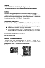
Table of Contents Box Contents ...6 OptionalItems ...6 GA-MA790X-UD4P Motherboard Layout 7 Block Diagram ...8 Chapter 1 Hardware Installation 9 1-1 Installation Precautions 9 1-2 Product Specifications 10 1-3 Installing the CPU and CPU Cooler 13 ... Installing the SATA Bracket 20 1-8 Back Panel Connectors 21 1-9 Internal Connectors 23 Chapter 2 BIOS Setup 35 2-1 Startup Screen 36 2-2 The Main Menu 37 2-3 MB Intelligent Tweaker(M.I.T 39 2-4 Standard CMOS Features 44 2-5 Advanced BIOS Features 46 2-6 IntegratedPeripherals 48 2-7 Power Management Setup 51 2-8 PC Health Status 53 2-9...
Table of Contents Box Contents ...6 OptionalItems ...6 GA-MA790X-UD4P Motherboard Layout 7 Block Diagram ...8 Chapter 1 Hardware Installation 9 1-1 Installation Precautions 9 1-2 Product Specifications 10 1-3 Installing the CPU and CPU Cooler 13 ... Installing the SATA Bracket 20 1-8 Back Panel Connectors 21 1-9 Internal Connectors 23 Chapter 2 BIOS Setup 35 2-1 Startup Screen 36 2-2 The Main Menu 37 2-3 MB Intelligent Tweaker(M.I.T 39 2-4 Standard CMOS Features 44 2-5 Advanced BIOS Features 46 2-6 IntegratedPeripherals 48 2-7 Power Management Setup 51 2-8 PC Health Status 53 2-9...
Manual
Page 5
... ...61 3-6 Download Center 62 Chapter 4 Unique Features 63 4-1 Xpress Recovery2 63 4-2 BIOS Update Utilities 66 4-2-1 Updating the BIOS with the Q-Flash Utility 66 4-2-2 Updating the BIOS with the @BIOS Utility 69 4-3 EasyTune 6 ...70 4-4 Easy Energy Saver 71 4-5 Q-Share ...73 ...4-6 Time Repair ...74 Chapter 5 Appendix ...75 5-1 Configuring SATA Hard Drive(s 75 5-1-1 Configuring AMD SB750 SATA Controllers 75 5-1-2 Configuring GIGABYTE...
... ...61 3-6 Download Center 62 Chapter 4 Unique Features 63 4-1 Xpress Recovery2 63 4-2 BIOS Update Utilities 66 4-2-1 Updating the BIOS with the Q-Flash Utility 66 4-2-2 Updating the BIOS with the @BIOS Utility 69 4-3 EasyTune 6 ...70 4-4 Easy Energy Saver 71 4-5 Q-Share ...73 ...4-6 Time Repair ...74 Chapter 5 Appendix ...75 5-1 Configuring SATA Hard Drive(s 75 5-1-1 Configuring AMD SB750 SATA Controllers 75 5-1-2 Configuring GIGABYTE...
Manual
Page 8
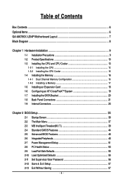
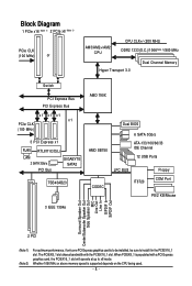
... PCI Express Bus x1 x1 x1 x1 PCIe CLK (100 MHz) 3 PCI Express x1 RJ45 RTL8111C/D(L) LAN 2 SATA 3Gb/s PCI Bus GIGABYTE SATA2 TSB43AB23 AMD 790X AMD SB750 Dual BIOS 6 SATA 3Gb/s ATA-133/100/66/33 IDE Channel 12 USB Ports CODEC LPC BUS IT8720 Floppy COM Port PS/2 KB/Mouse...
... PCI Express Bus x1 x1 x1 x1 PCIe CLK (100 MHz) 3 PCI Express x1 RJ45 RTL8111C/D(L) LAN 2 SATA 3Gb/s PCI Bus GIGABYTE SATA2 TSB43AB23 AMD 790X AMD SB750 Dual BIOS 6 SATA 3Gb/s ATA-133/100/66/33 IDE Channel 12 USB Ports CODEC LPC BUS IT8720 Floppy COM Port PS/2 KB/Mouse...
Manual
Page 11
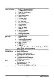
... CPU/System/Power fan speed detection CPU overheating warning CPU/System/Power fan fail warning CPU/System fan speed control (Note 4) BIOS 2 x 8 Mbit flash Use of licensed AWARD BIOS Support for DualBIOSTM PnP 1.0a, DMI 2.0, SM...
... CPU/System/Power fan speed detection CPU overheating warning CPU/System/Power fan fail warning CPU/System fan speed control (Note 4) BIOS 2 x 8 Mbit flash Use of licensed AWARD BIOS Support for DualBIOSTM PnP 1.0a, DMI 2.0, SM...
Manual
Page 12
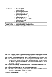
When PCIEX8_1 is populated with the PCIEX16_1 slot. GA-MA790X-UD4P Motherboard - 12 - The PCIEX8_1 slot shares bandwidth with a PCI Express graphics card, the PCIEX16_1 slot will operate at up to x8 mode. (Note 4) Whether the.../AM2+ PhenomTM Series CPU toenable support for Easy Energy Saver. Unique Features Bundled Software Operating System Form Factor Support for @BIOS Support for Q-Flash Support for Virtual Dual BIOS Support for Download Center Support for Xpress Install Support for Xpress Recovery2 Support for EasyTune ...
When PCIEX8_1 is populated with the PCIEX16_1 slot. GA-MA790X-UD4P Motherboard - 12 - The PCIEX8_1 slot shares bandwidth with a PCI Express graphics card, the PCIEX16_1 slot will operate at up to x8 mode. (Note 4) Whether the.../AM2+ PhenomTM Series CPU toenable support for Easy Energy Saver. Unique Features Bundled Software Operating System Form Factor Support for @BIOS Support for Q-Flash Support for Virtual Dual BIOS Support for Download Center Support for Xpress Install Support for Xpress Recovery2 Support for EasyTune ...
Manual
Page 16
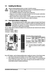
... that memory of the same capacity, brand, speed, and chips be used . (Go to GIGABYTE's website for optimum performance. DS/SS DS/SS Four Modules DS/SS DS/SS DS/SS DS... Memory Configurations Table DDR2_1 DDR2_2 DDR2_3 DDR2_4 Two Modules DS/SS DS/SS - - - - - - - - GA-MA790X-UD4P Motherboard - 16 - It is recommended that memory of the memory. After the memory is installed. 2. Dual Channel mode...used and installed in only one DDR2 memory module is installed, the BIOS will double the original memory bandwidth. DDR2_1 DDR2_2 DDR2_3 DDR2_4 Due to prevent hardware damage....
... that memory of the same capacity, brand, speed, and chips be used . (Go to GIGABYTE's website for optimum performance. DS/SS DS/SS Four Modules DS/SS DS/SS DS/SS DS... Memory Configurations Table DDR2_1 DDR2_2 DDR2_3 DDR2_4 Two Modules DS/SS DS/SS - - - - - - - - GA-MA790X-UD4P Motherboard - 16 - It is recommended that memory of the memory. After the memory is installed. 2. Dual Channel mode...used and installed in only one DDR2 memory module is installed, the BIOS will double the original memory bandwidth. DDR2_1 DDR2_2 DDR2_3 DDR2_4 Due to prevent hardware damage....

Manual
Page 18
... Express x1 Slot PCI Express x16 Slot (PCIEX16_1) PCI Express x16 Slot (PCIEX8_1) PCI Slot Follow the steps below to make any required BIOS changes for your computer. After installing all expansion cards, replace the chassis cover(s). 6. Secure the card's metal bracket to release the card and... straight up from the PCIEX8_1 slot: Press the white latch at the end of the card until it is securely seated in your card. GA-MA790X-UD4P Motherboard - 18 - • Removing the Card from the slot. Carefully read the manual that supports your operating system. Make sure the ...
... Express x1 Slot PCI Express x16 Slot (PCIEX16_1) PCI Express x16 Slot (PCIEX8_1) PCI Slot Follow the steps below to make any required BIOS changes for your computer. After installing all expansion cards, replace the chassis cover(s). 6. Secure the card's metal bracket to release the card and... straight up from the PCIEX8_1 slot: Press the white latch at the end of the card until it is securely seated in your card. GA-MA790X-UD4P Motherboard - 18 - • Removing the Card from the slot. Carefully read the manual that supports your operating system. Make sure the ...
Manual
Page 19
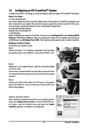
.... Hardware Installation Power Requirements: Use a power supply that came with a single PCIe x16 graphics card and then go to BIOS Setup to set Init Display First under Advanced BIOS Features in your system. BIOS Settings: Before configuring your system for CrossFireX, make sure to set Init Display First to PEG first. (Start your...
.... Hardware Installation Power Requirements: Use a power supply that came with a single PCIe x16 graphics card and then go to BIOS Setup to set Init Display First under Advanced BIOS Features in your system. BIOS Settings: Before configuring your system for CrossFireX, make sure to set Init Display First to PEG first. (Start your...
Manual
Page 28
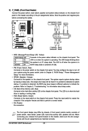
... S1 sleep state. Press the reset switch to restart the computer if the computer freezes and fails to the speaker on the chassis front panel. GA-MA790X-UD4P Motherboard - 28 - RESRES+ NC Hard Drive Activity LED Reset Switch • MSG (Message/Power/Sleep LED, Yellow): System Status LED Connects to ... status by chassis. The LED is on when the hard drive is operating. The LED keeps blinking when S1 Blinking the system is detected, the BIOS may differ by issuing a beep code. Message/Power/ Power Sleep LED Switch Speaker MSG+ MSG- PW+ PWSPEAK+ SPEAK- 2 20 1 19 HD+ HD- ...
... S1 sleep state. Press the reset switch to restart the computer if the computer freezes and fails to the speaker on the chassis front panel. GA-MA790X-UD4P Motherboard - 28 - RESRES+ NC Hard Drive Activity LED Reset Switch • MSG (Message/Power/Sleep LED, Yellow): System Status LED Connects to ... status by chassis. The LED is on when the hard drive is operating. The LED keeps blinking when S1 Blinking the system is detected, the BIOS may differ by issuing a beep code. Message/Power/ Power Sleep LED Switch Speaker MSG+ MSG- PW+ PWSPEAK+ SPEAK- 2 20 1 19 HD+ HD- ...
Manual
Page 33
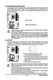
...jumper cap on your computer, be sure to remove the jumper cap from the battery holder and wait for BIOS configurations). 21) BATTERY The battery provides power to keep the values (such as BIOS configurations, date, and time information) in accordance with an equivalent one minute. (Or use a metal ...the power cord before turning on the two pins to temporarily short the two pins or use a metal object like a screwdriver to Chapter 2, "BIOS Setup," for one . Turn off your computer and unplug the power cord from the power outlet before clearing the CMOS values. • After...
...jumper cap on your computer, be sure to remove the jumper cap from the battery holder and wait for BIOS configurations). 21) BATTERY The battery provides power to keep the values (such as BIOS configurations, date, and time information) in accordance with an equivalent one minute. (Or use a metal ...the power cord before turning on the two pins to temporarily short the two pins or use a metal object like a screwdriver to Chapter 2, "BIOS Setup," for one . Turn off your computer and unplug the power cord from the power outlet before clearing the CMOS values. • After...
Manual
Page 35
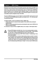
... modify basic system configuration settings or to activate certain system features. To access the BIOS Setup program, press the key during the POST. To upgrade the BIOS, use either the GIGABYTE Q-Flash or @BIOS utility . • Q-Flash allows the user to keep the configuration values in ...the CMOS on using the current version of the BIOS Setup program. BIOS Setup To flash the BIOS, do not encounter problems using the...
... modify basic system configuration settings or to activate certain system features. To access the BIOS Setup program, press the key during the POST. To upgrade the BIOS, use either the GIGABYTE Q-Flash or @BIOS utility . • Q-Flash allows the user to keep the configuration values in ...the CMOS on using the current version of the BIOS Setup program. BIOS Setup To flash the BIOS, do not encounter problems using the...
Manual
Page 36
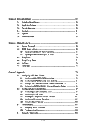
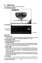
... down arrow key< > to select the first boot device, then press to enter BIOS Setup first. Note: The setting in Boot Menu. GA-MA790X-UD4P Motherboard - 36 - The POST Screen Motherboard Model BIOS Version Award Modular BIOS v6.00PG, An Energy Star Ally Copyright (C) 1984-2009, Award Software, Inc. ...computer boots. Function Keys : BIOS Setup : XpressRecovery2 : Boot Menu : Qflash 01/23/2009-RD790-SB750-7A66AG08C-00 Function Keys Function Keys: : POST SCREEN Press the key to set the first boot device without having to accept. To exit Boot Menu, press . GA-MA790X-UD4P E3 . . . . In...
... down arrow key< > to select the first boot device, then press to enter BIOS Setup first. Note: The setting in Boot Menu. GA-MA790X-UD4P Motherboard - 36 - The POST Screen Motherboard Model BIOS Version Award Modular BIOS v6.00PG, An Energy Star Ally Copyright (C) 1984-2009, Award Software, Inc. ...computer boots. Function Keys : BIOS Setup : XpressRecovery2 : Boot Menu : Qflash 01/23/2009-RD790-SB750-7A66AG08C-00 Function Keys Function Keys: : POST SCREEN Press the key to set the first boot device without having to accept. To exit Boot Menu, press . GA-MA790X-UD4P E3 . . . . In...
Manual
Page 37
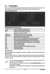
... Exit Setup Exit Without Saving ESC: Quit F8: Q-Flash Select Item F10: Save & Exit Setup F11: Save CMOS to BIOS Load CMOS from BIOS Main Menu Help The onscreen description of function keys available for the current submenus Access the Q-Flash utility Display system information Save ...all the changes and exit the BIOS Setup program Save CMOS to BIOS F12: Load CMOS from BIOS Time, Date, Hard Disk Type... Press to exit the help screen (General Help) of a highlighted ...
... Exit Setup Exit Without Saving ESC: Quit F8: Q-Flash Select Item F10: Save & Exit Setup F11: Save CMOS to BIOS Load CMOS from BIOS Main Menu Help The onscreen description of function keys available for the current submenus Access the Q-Flash utility Display system information Save ...all the changes and exit the BIOS Setup program Save CMOS to BIOS F12: Load CMOS from BIOS Time, Date, Hard Disk Type... Press to exit the help screen (General Help) of a highlighted ...
Manual
Page 38
.... Save & Exit Setup Save all the changes made in the BIOS Setup program to the CMOS and exit BIOS Setup. (Pressing can use this task.) GA-MA790X-UD4P Motherboard - 38 - It allows you to view the BIOS settings but not to make changes in effect. An user password only allows ...you to restrict access to a profile. It allows you to save the current BIOS settings to the system and BIOS Setup. You can also...
.... Save & Exit Setup Save all the changes made in the BIOS Setup program to the CMOS and exit BIOS Setup. (Pressing can use this task.) GA-MA790X-UD4P Motherboard - 38 - It allows you to view the BIOS settings but not to make changes in effect. An user password only allows ...you to restrict access to a profile. It allows you to save the current BIOS settings to the system and BIOS Setup. You can also...
Manual
Page 39
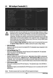
Auto (default) allows BIOS to 500 MHz. The adjustable range is from 200 MHz to automatically adjust the CPU host frequency. 2-3 MB Intelligent Tweaker(M.I.T.) CMOS Setup Utility-Copyright (C) 1984-... overclock/overvoltage may result in system's failure to default values. This page is dependent on the CPU being used . Note: If your overall system configurations. BIOS Setup CPU Host Clock Control Enables or disables the control of these components. CPU Frequency (Mhz) Allows you not to alter the default settings to...
Auto (default) allows BIOS to 500 MHz. The adjustable range is from 200 MHz to automatically adjust the CPU host frequency. 2-3 MB Intelligent Tweaker(M.I.T.) CMOS Setup Utility-Copyright (C) 1984-... overclock/overvoltage may result in system's failure to default values. This page is dependent on the CPU being used . Note: If your overall system configurations. BIOS Setup CPU Host Clock Control Enables or disables the control of these components. CPU Frequency (Mhz) Allows you not to alter the default settings to...
Manual
Page 40
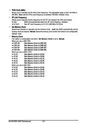
... to X5.33. X5.33 Sets Memory Clock to X3.33. When you use a AM2+ CPU: X2.00 Sets Memory Clock to DDR 400. Auto BIOS will automatically adjust the HT Link Frequency. (Default) X1~X13 Sets HT Link Frequency to X2.00. Manual allows the memory clock control item below... Sets Memory Clock to manually set the memory clock. Set Memory Clock Determines whether to X4.00. X3.33 Sets Memory Clock to X4.00. GA-MA790X-UD4P Motherboard - 40 - X4.00 Sets Memory Clock to X3.33. PCIE Clock (MHz) Allows you to manually set the frequency for the HT Link between...
... to X5.33. X5.33 Sets Memory Clock to X3.33. When you use a AM2+ CPU: X2.00 Sets Memory Clock to DDR 400. Auto BIOS will automatically adjust the HT Link Frequency. (Default) X1~X13 Sets HT Link Frequency to X2.00. Manual allows the memory clock control item below... Sets Memory Clock to manually set the memory clock. Set Memory Clock Determines whether to X4.00. X3.33 Sets Memory Clock to X4.00. GA-MA790X-UD4P Motherboard - 40 - X4.00 Sets Memory Clock to X3.33. PCIE Clock (MHz) Allows you to manually set the frequency for the HT Link between...
Manual
Page 41
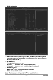
... are synchronous to those under the four items above are : Auto (default), Manual. (Note) This item is present only if you to be configurable. Auto - - BIOS Setup Ganged Sets memory control mode to CAS R/W Delay x Row Precharge Time x Minimum RAS Active Time x 1T/2T Command Timing x TwTr Command Delay x Trfc0 for...
... are synchronous to those under the four items above are : Auto (default), Manual. (Note) This item is present only if you to be configurable. Auto - - BIOS Setup Ganged Sets memory control mode to CAS R/W Delay x Row Precharge Time x Minimum RAS Active Time x 1T/2T Command Timing x TwTr Command Delay x Trfc0 for...
Manual
Page 42
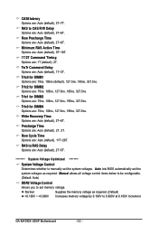
..., 105ns, 127.5ns, 195ns, 327.5ns. Trfc2 for DIMM1 Options are : Auto (default), 3T~6T. GA-MA790X-UD4P Motherboard - 42 - TwTr Command Delay Options are : Auto (default), 3T~6T. Normal Supplies the memory voltage as required. Auto lets BIOS automatically set the system voltages. Row Precharge Time Options are : Auto (default), 1T~3T. Trfc0...
..., 105ns, 127.5ns, 195ns, 327.5ns. Trfc2 for DIMM1 Options are : Auto (default), 3T~6T. GA-MA790X-UD4P Motherboard - 42 - TwTr Command Delay Options are : Auto (default), 3T~6T. Normal Supplies the memory voltage as required. Auto lets BIOS automatically set the system voltages. Row Precharge Time Options are : Auto (default), 1T~3T. Trfc0...
Manual
Page 43
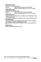
... of the CPU. Normal Supplies the North Bridge voltage as required. (Default) +0.1V ~ +0.3V Increases South Bridge voltage by 0.1V to 0.3V at 0.1V increment. BIOS Setup CPU NB VID Control (Note) Allows you to set the CPU voltage. Normal sets the CPU Northbridge VID voltage as required. SouthBridge Volt Control...
... of the CPU. Normal Supplies the North Bridge voltage as required. (Default) +0.1V ~ +0.3V Increases South Bridge voltage by 0.1V to 0.3V at 0.1V increment. BIOS Setup CPU NB VID Control (Note) Allows you to set the CPU voltage. Normal sets the CPU Northbridge VID voltage as required. SouthBridge Volt Control...


