Manual
Page 1
GA-MA69VM-S2 AMD AthlonTM 64 FX / AthlonTM 64 X2 Dual-Core / AMD AthlonTM 64 / SempronTM AM2 Processor Motherboard User's Manual Rev. 1002 12ME-MA69VMS2-1002R * The WEEE marking on the product indicates this product must not be disposed of with user's other household waste and must be handed over to a designated collection point for the recycling of waste electrical and electronic equipment!! * The WEEE marking applies only in European Union's member states.
GA-MA69VM-S2 AMD AthlonTM 64 FX / AthlonTM 64 X2 Dual-Core / AMD AthlonTM 64 / SempronTM AM2 Processor Motherboard User's Manual Rev. 1002 12ME-MA69VMS2-1002R * The WEEE marking on the product indicates this product must not be disposed of with user's other household waste and must be handed over to a designated collection point for the recycling of waste electrical and electronic equipment!! * The WEEE marking applies only in European Union's member states.
Manual
Page 4
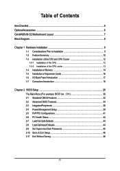
Table of Contents ItemChecklist ...6 OptionalAccessories ...6 GA-MA69VM-S2 Motherboard Layout 7 Block Diagram ...8 Chapter 1 Hardware Installation 9 1-1 Considerations Prior to Installation 9 1-2 Feature Summary 10 1-3 Installation of the CPU and CPU Cooler 12 1-3-1 Installation of the CPU ...
Table of Contents ItemChecklist ...6 OptionalAccessories ...6 GA-MA69VM-S2 Motherboard Layout 7 Block Diagram ...8 Chapter 1 Hardware Installation 9 1-1 Considerations Prior to Installation 9 1-2 Feature Summary 10 1-3 Installation of the CPU and CPU Cooler 12 1-3-1 Installation of the CPU ...
Manual
Page 7
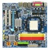
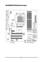
ATX GA-MA69VM-S2 Motherboard Layout MS / KB ATX_12V COMA Socket AM2 LPT VGA CPU_FAN USB USB LAN TV AUDIO IT8716 CI BIOS PCIE_4 GA-MA69VM-S2 AMD 690V F_AUDIO RTL8110SC PCIE_16 PCI1 PCI2 CODEC COMB CD_IN SPDIF_IO DDRII1 DDRII2 DDRII3 DDRII4 IDE SATAII2 SATAII0 AMD SB600 SYS_FAN SATAII3 BATTERY SATAII1 CLR_CMOS F_PANEL F_USB1 F_USB2 F_USB3 PWR_LED FDD - 7 -
ATX GA-MA69VM-S2 Motherboard Layout MS / KB ATX_12V COMA Socket AM2 LPT VGA CPU_FAN USB USB LAN TV AUDIO IT8716 CI BIOS PCIE_4 GA-MA69VM-S2 AMD 690V F_AUDIO RTL8110SC PCIE_16 PCI1 PCI2 CODEC COMB CD_IN SPDIF_IO DDRII1 DDRII2 DDRII3 DDRII4 IDE SATAII2 SATAII0 AMD SB600 SYS_FAN SATAII3 BATTERY SATAII1 CLR_CMOS F_PANEL F_USB1 F_USB2 F_USB3 PWR_LED FDD - 7 -
Manual
Page 9
... to come in the user manual. 3. Before using the product, please verify that the power supply is best to be an unofficial Gigabyte product. - 9 - Damage due to the user. 8. Please verify that all cables and power connectors are uncertain about any metal ... Instances of the product, please consult a certified computer technician. Damage as a result of violating the conditions recommended in contact with the motherboard circuit or its power cord. 2. Product determined to wear an electrostatic discharge (ESD) cuff when handling electronic components (CPU, RAM). ...
... to come in the user manual. 3. Before using the product, please verify that the power supply is best to be an unofficial Gigabyte product. - 9 - Damage due to the user. 8. Please verify that all cables and power connectors are uncertain about any metal ... Instances of the product, please consult a certified computer technician. Damage as a result of violating the conditions recommended in contact with the motherboard circuit or its power cord. 2. Product determined to wear an electrostatic discharge (ESD) cuff when handling electronic components (CPU, RAM). ...
Manual
Page 10
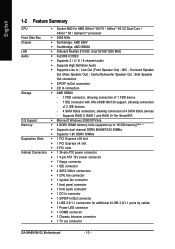
... CPU Š Socket AM2 for additional 6 USB 2.0/1.1 ports by cables Š 1 Power LED connector Š 1 COMB connector Š 1 Chassis Intrusion connector Š 1 TV out connector GA-MA69VM-S2 Motherboard - 10 - MIC ; Line Out (Front Speaker Out) ;
... CPU Š Socket AM2 for additional 6 USB 2.0/1.1 ports by cables Š 1 Power LED connector Š 1 COMB connector Š 1 Chassis Intrusion connector Š 1 TV out connector GA-MA69VM-S2 Motherboard - 10 - MIC ; Line Out (Front Speaker Out) ;

Manual
Page 11
... is installed, the actual memory available for the operating system will depend on the CPU you install. (Note 3) EasyTune functions may vary depending on different motherboards. - 11 - English Rear Panel I/O Š 1 PS/2 keyboard port Š 1 PS/2 mouse port Š 1 parallel port Š 1 COMA port Š 1 VGA port Š 4 USB 2.0/1.1 ports Š...
... is installed, the actual memory available for the operating system will depend on the CPU you install. (Note 3) EasyTune functions may vary depending on different motherboards. - 11 - English Rear Panel I/O Š 1 PS/2 keyboard port Š 1 PS/2 mouse port Š 1 parallel port Š 1 COMA port Š 1 VGA port Š 4 USB 2.0/1.1 ports Š...
Manual
Page 12
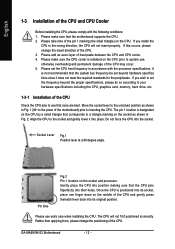
...pin 1 location is positioned into its original position. Pin One Fig.2 Pin 1 location on the CPU. GA-MA69VM-S2 Motherboard - 12 - If you install the CPU in Fig. 1 (90o to the plane of the motherboard) prior to system use extra care when installing the CPU. Socket Lever Fig.1 Position lever at a 90 ...1-3-1 Installation of the CPU Check the CPU pins to a triangle marking on the CPU by a small triangle that corresponds to see that the motherboard supports the CPU. 2. Please make sure that none are bent. It is installed on the middle of the CPU and gently press themetal lever...
...pin 1 location is positioned into its original position. Pin One Fig.2 Pin 1 location on the CPU. GA-MA69VM-S2 Motherboard - 12 - If you install the CPU in Fig. 1 (90o to the plane of the motherboard) prior to system use extra care when installing the CPU. Socket Lever Fig.1 Position lever at a 90 ...1-3-1 Installation of the CPU Check the CPU pins to a triangle marking on the CPU by a small triangle that corresponds to see that the motherboard supports the CPU. 2. Please make sure that none are bent. It is installed on the middle of the CPU and gently press themetal lever...
Manual
Page 13
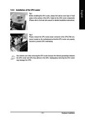
... the CPU. English 1-3-2 Installation of the CPU cooler Fig.1 Before installing the CPU cooler, please first add an even layer of heat paste on the motherboard so that the CPU cooler can properly function to prevent CPU overheating.
... the CPU. English 1-3-2 Installation of the CPU cooler Fig.1 Before installing the CPU cooler, please first add an even layer of heat paste on the motherboard so that the CPU cooler can properly function to prevent CPU overheating.
Manual
Page 14
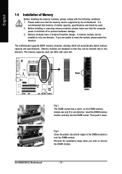
... direction. Fig.2 Close the plastic clip at both edges of similar capacity, specifications and brand be used. 2. The motherboard supports DDRII memory modules, whereby BIOS will automatically detect memory capacity and specifications. Reverse the installation steps when you are ...can only fit in one direction. It is supported by the motherboard. Insert the DIMM memory module vertically into the DIMM socket. English 1-4 Installation of Memory Before installing the memory modules, please comply with each slot. Then push it down. GA-MA69VM-S2 Motherboard - 14 -
... direction. Fig.2 Close the plastic clip at both edges of similar capacity, specifications and brand be used. 2. The motherboard supports DDRII memory modules, whereby BIOS will automatically detect memory capacity and specifications. Reverse the installation steps when you are ...can only fit in one direction. It is supported by the motherboard. Insert the DIMM memory module vertically into the DIMM socket. English 1-4 Installation of Memory Before installing the memory modules, please comply with each slot. Then push it down. GA-MA69VM-S2 Motherboard - 14 -
Manual
Page 16
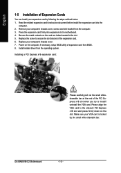
...x16 slot when you try to the onboard PCI Express x16 slot and press firmly down on the card are indeed seated in motherboard. 4. Make sure your expansion card by the small white-drawable bar. Power on the computer, if necessary, setup BIOS ...chassis cover. 7. Press the expansion card firmly into the computer. 2. Replace your computer's chassis cover, screws and slot bracket from BIOS. 8. GA-MA69VM-S2 Motherboard - 16 - Install related driver from the operating system. Read the related expansion card's instruction document before install the expansion card into expansion slot...
...x16 slot when you try to the onboard PCI Express x16 slot and press firmly down on the card are indeed seated in motherboard. 4. Make sure your expansion card by the small white-drawable bar. Power on the computer, if necessary, setup BIOS ...chassis cover. 7. Press the expansion card firmly into the computer. 2. Replace your computer's chassis cover, screws and slot bracket from BIOS. 8. GA-MA69VM-S2 Motherboard - 16 - Install related driver from the operating system. Read the related expansion card's instruction document before install the expansion card into expansion slot...
Manual
Page 18
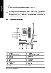
... configuration information. 1-7 Connectors Introduction 1 62 3 16 5 13 10 7 4 14 9 17 18 15 11 12 8 1) ATX_12V 2) ATX (Power Connector) 3) CPU_FAN 4) SYS_FAN 5) FDD 6) IDE 7) SATAII0 /1 /2 /3 8) F_PANEL 9) CD_IN GA-MA69VM-S2 Motherboard 10) F_AUDIO 11) F_USB1 / F_USB2/ F_USB3 12) POWER_LED 13) CI 14) CLR_CMOS 15) BATTERY 16) TV 17) SPDIF_IO 18) COMB - 18 - English MIC In The...
... configuration information. 1-7 Connectors Introduction 1 62 3 16 5 13 10 7 4 14 9 17 18 15 11 12 8 1) ATX_12V 2) ATX (Power Connector) 3) CPU_FAN 4) SYS_FAN 5) FDD 6) IDE 7) SATAII0 /1 /2 /3 8) F_PANEL 9) CD_IN GA-MA69VM-S2 Motherboard 10) F_AUDIO 11) F_USB1 / F_USB2/ F_USB3 12) POWER_LED 13) CI 14) CLR_CMOS 15) BATTERY 16) TV 17) SPDIF_IO 18) COMB - 18 - English MIC In The...
Manual
Page 19
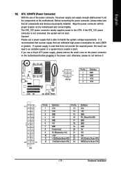
...for 24-pin ATX) - 19 - Please use a 24-pin ATX power supply, please remove the small cover on the power connector on the motherboard and connect tightly. Caution! If a power supply is used that does not provide the required power, the result can withstand high power consumption be ... greater). The ATX_12V power connector mainly supplies power to handle the system voltage requirements. Align the power connector with its proper location on the motherboard before plugging in the power cord; If the ATX_12V power connector is able to the CPU. If you use a power supply that is...
...for 24-pin ATX) - 19 - Please use a 24-pin ATX power supply, please remove the small cover on the power connector on the motherboard and connect tightly. Caution! If a power supply is used that does not provide the required power, the result can withstand high power consumption be ... greater). The ATX_12V power connector mainly supplies power to handle the system voltage requirements. Align the power connector with its proper location on the motherboard before plugging in the power cord; If the ATX_12V power connector is able to the CPU. If you use a power supply that is...
Manual
Page 20
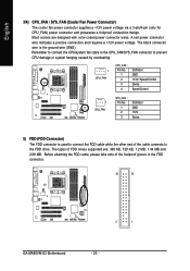
... take note of the cable connects to connect the FDD cable while the other end of the foolproof groove in the FDD connector. 34 33 2 1 GA-MA69VM-S2 Motherboard - 20 - The types of FDD drives supported are designed with color-coded power connector wires.
... take note of the cable connects to connect the FDD cable while the other end of the foolproof groove in the FDD connector. 34 33 2 1 GA-MA69VM-S2 Motherboard - 20 - The types of FDD drives supported are designed with color-coded power connector wires.
Manual
Page 22
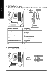
.../Power/Sleep LED) NC Reset Switch IDE Hard Disk Active LED Pin 1: LED anode(+) Pin 2: LED cathode(-) Pin 1: Power Pin 2- Definition 1 CD-L 1 2 GND 3 GND 4 CD-R GA-MA69VM-S2 Motherboard - 22 - English 8) F_PANEL (Front Panel Jumper) Please connect the power LED, PC speaker, reset switch and power switch etc of your chassis front panel to...
.../Power/Sleep LED) NC Reset Switch IDE Hard Disk Active LED Pin 1: LED anode(+) Pin 2: LED cathode(-) Pin 1: Power Pin 2- Definition 1 CD-L 1 2 GND 3 GND 4 CD-R GA-MA69VM-S2 Motherboard - 22 - English 8) F_PANEL (Front Panel Jumper) Please connect the power LED, PC speaker, reset switch and power switch etc of your chassis front panel to...
Manual
Page 24
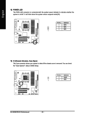
You can check the "Case Opened" status in BIOS Setup. Pin No. Pin No. It will blink when the system enters suspend mode(S1). Definition 1 MPD+ 2 MPD- 3 MPD- 1 13) CI (Chassis Intrusion, Case Open) This 2-pin connector allows your system to indicate whether the system is removed. English 12) POWER_LED The PWR_LED connector is connected with the system power indicator to detect if the chassis cover is on/off. Definition 1 Signal 2 GND 1 GA-MA69VM-S2 Motherboard - 24 -
You can check the "Case Opened" status in BIOS Setup. Pin No. Pin No. It will blink when the system enters suspend mode(S1). Definition 1 MPD+ 2 MPD- 3 MPD- 1 13) CI (Chassis Intrusion, Case Open) This 2-pin connector allows your system to indicate whether the system is removed. English 12) POWER_LED The PWR_LED connector is connected with the system power indicator to detect if the chassis cover is on/off. Definition 1 Signal 2 GND 1 GA-MA69VM-S2 Motherboard - 24 -
Manual
Page 26
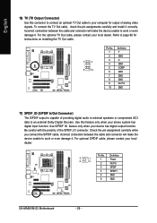
For optional S/PDIF cable, please contact your local dealer. Definition 5 1 6 2 1 Power 2 No Pin 3 SPDIF 4 SPDIFI 5 GND 6 GND GA-MA69VM-S2 Motherboard - 26 - For the optional TV Out cable, please contact your local dealer. Be careful with the polarity of analog video signals. Pin No. Use this ...
For optional S/PDIF cable, please contact your local dealer. Definition 5 1 6 2 1 Power 2 No Pin 3 SPDIF 4 SPDIFI 5 GND 6 GND GA-MA69VM-S2 Motherboard - 26 - For the optional TV Out cable, please contact your local dealer. Be careful with the polarity of analog video signals. Pin No. Use this ...
Manual
Page 29
...table Load the Optimized Defaults Q-Flash utility System Information Save all the CMOS changes, only for Main Menu Main Menu The on the motherboard supplies the necessary power to use and the possible selections for Option Page Setup Menu Load the fail-safe default CMOS value from ... Setup Menu Item Help Restore the previous CMOS value from CMOS, only for the highlighted item. CONTROL KEYS Move to a new BIOS, either GIGABYTE's Q-Flash or @BIOS utility can enter the BIOS setup screen by pressing "Ctrl + F1". The CMOS SETUP saves the configuration in system malfunction....
...table Load the Optimized Defaults Q-Flash utility System Information Save all the CMOS changes, only for Main Menu Main Menu The on the motherboard supplies the necessary power to use and the possible selections for Option Page Setup Menu Load the fail-safe default CMOS value from ... Setup Menu Item Help Restore the previous CMOS value from CMOS, only for the highlighted item. CONTROL KEYS Move to a new BIOS, either GIGABYTE's Q-Flash or @BIOS utility can enter the BIOS setup screen by pressing "Ctrl + F1". The CMOS SETUP saves the configuration in system malfunction....
Manual
Page 30
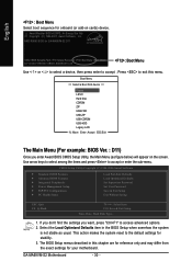
... : Boot Menu Select boot sequence for onboard (or add-on the screen. Select the Load Optimized Defaults item in this menu. AMD RS690 BIOS for GA-MA69VM-S2 D11 . . . . :BIOS Setup/Q-Flash :Xpress Recovery2 :Boot Menu :Qflash 02/14/2007-RS690V-SB600-6A669G01C-00 : Boot Menu Use < > or < > ... Date, Hard Disk Type... 1. Press to exit this chapter are for reference only and may differ from the exact settings for stability. 3. GA-MA69VM-S2 Motherboard - 30 - This action makes the system reset to accept or enter the sub-menu. Use arrow keys to select among the items and ...
... : Boot Menu Select boot sequence for onboard (or add-on the screen. Select the Load Optimized Defaults item in this menu. AMD RS690 BIOS for GA-MA69VM-S2 D11 . . . . :BIOS Setup/Q-Flash :Xpress Recovery2 :Boot Menu :Qflash 02/14/2007-RS690V-SB600-6A669G01C-00 : Boot Menu Use < > or < > ... Date, Hard Disk Type... 1. Press to exit this chapter are for reference only and may differ from the exact settings for stability. 3. GA-MA69VM-S2 Motherboard - 30 - This action makes the system reset to accept or enter the sub-menu. Use arrow keys to select among the items and ...
Manual
Page 32
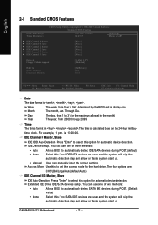
... 2000 through 2099 Time The times format in the month) Year The year, from Sun to select this option for automatic device detection. For example, 1 p.m. GA-MA69VM-S2 Motherboard - 32 - Access Mode Use this option for automatic device detection. The four options are used and the system will skip the automatic detection step and...
... 2000 through 2099 Time The times format in the month) Year The year, from Sun to select this option for automatic device detection. For example, 1 p.m. GA-MA69VM-S2 Motherboard - 32 - Access Mode Use this option for automatic device detection. The four options are used and the system will skip the automatic detection step and...
Manual
Page 33
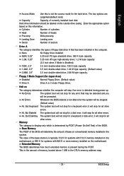
...25 inch AT-type high-density drive; 1.2 M byte capacity (3.5 inch when 3 Mode is typically 512 K for systems with 512 K memory installed on the motherboard, or 640 K for any error that has been installed in the system. No Errors The system boot will determine the amount of the BIOS. Base... installed in the computer. English Access Mode Use this information. Enter the appropriate option based on the outside drive casing. Halt on the motherboard. All, But Disk/Key The system boot will not stop for a keyboard error; The category is display-only which is detected during ...
...25 inch AT-type high-density drive; 1.2 M byte capacity (3.5 inch when 3 Mode is typically 512 K for systems with 512 K memory installed on the motherboard, or 640 K for any error that has been installed in the system. No Errors The system boot will determine the amount of the BIOS. Base... installed in the computer. English Access Mode Use this information. Enter the appropriate option based on the outside drive casing. Halt on the motherboard. All, But Disk/Key The system boot will not stop for a keyboard error; The category is display-only which is detected during ...


