Manual
Page 1
GA-MA69VM-S2 AMD AthlonTM 64 FX / AthlonTM 64 X2 Dual-Core / AMD AthlonTM 64 / SempronTM AM2 Processor Motherboard User's Manual Rev. 1002 12ME-MA69VMS2-1002R * The WEEE marking on the product indicates this product must not be disposed of with user's other household waste and must be handed over to a designated collection point for the recycling of waste electrical and electronic equipment!! * The WEEE marking applies only in European Union's member states.
GA-MA69VM-S2 AMD AthlonTM 64 FX / AthlonTM 64 X2 Dual-Core / AMD AthlonTM 64 / SempronTM AM2 Processor Motherboard User's Manual Rev. 1002 12ME-MA69VMS2-1002R * The WEEE marking on the product indicates this product must not be disposed of with user's other household waste and must be handed over to a designated collection point for the recycling of waste electrical and electronic equipment!! * The WEEE marking applies only in European Union's member states.
Manual
Page 4
Table of Contents ItemChecklist ...6 OptionalAccessories ...6 GA-MA69VM-S2 Motherboard Layout 7 Block Diagram ...8 Chapter 1 Hardware Installation 9 1-1 Considerations Prior to Installation 9 1-2 Feature Summary 10 1-3 Installation of the CPU and CPU Cooler 12 1-3-1 Installation of the ...
Table of Contents ItemChecklist ...6 OptionalAccessories ...6 GA-MA69VM-S2 Motherboard Layout 7 Block Diagram ...8 Chapter 1 Hardware Installation 9 1-1 Considerations Prior to Installation 9 1-2 Feature Summary 10 1-3 Installation of the CPU and CPU Cooler 12 1-3-1 Installation of the ...
Manual
Page 7
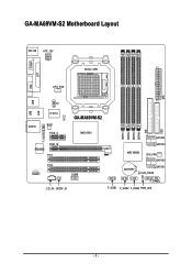
ATX GA-MA69VM-S2 Motherboard Layout MS / KB ATX_12V COMA Socket AM2 LPT VGA CPU_FAN USB USB LAN TV AUDIO IT8716 CI BIOS PCIE_4 GA-MA69VM-S2 AMD 690V F_AUDIO RTL8110SC PCIE_16 PCI1 PCI2 CODEC COMB CD_IN SPDIF_IO DDRII1 DDRII2 DDRII3 DDRII4 IDE SATAII2 SATAII0 AMD SB600 SYS_FAN SATAII3 BATTERY SATAII1 CLR_CMOS F_PANEL F_USB1 F_USB2 F_USB3 PWR_LED FDD - 7 -
ATX GA-MA69VM-S2 Motherboard Layout MS / KB ATX_12V COMA Socket AM2 LPT VGA CPU_FAN USB USB LAN TV AUDIO IT8716 CI BIOS PCIE_4 GA-MA69VM-S2 AMD 690V F_AUDIO RTL8110SC PCIE_16 PCI1 PCI2 CODEC COMB CD_IN SPDIF_IO DDRII1 DDRII2 DDRII3 DDRII4 IDE SATAII2 SATAII0 AMD SB600 SYS_FAN SATAII3 BATTERY SATAII1 CLR_CMOS F_PANEL F_USB1 F_USB2 F_USB3 PWR_LED FDD - 7 -
Manual
Page 10
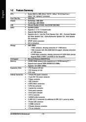
... CPU Š Socket AM2 for additional 6 USB 2.0/1.1 ports by cables Š 1 Power LED connector Š 1 COMB connector Š 1 Chassis Intrusion connector Š 1 TV out connector GA-MA69VM-S2 Motherboard - 10 - Line Out (Front Speaker Out) ; Surround Speaker Out (Rear Speaker Out) ; Side Speaker Out connection Š S/PDIF In/Out connection Š CD In...
... CPU Š Socket AM2 for additional 6 USB 2.0/1.1 ports by cables Š 1 Power LED connector Š 1 COMB connector Š 1 Chassis Intrusion connector Š 1 TV out connector GA-MA69VM-S2 Motherboard - 10 - Line Out (Front Speaker Out) ; Surround Speaker Out (Rear Speaker Out) ; Side Speaker Out connection Š S/PDIF In/Out connection Š CD In...
Manual
Page 12
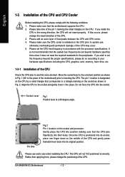
... the CPU, please comply with the processor specifications. Socket Lever Fig.1 Position lever at a 90 degree angle. Pin One Fig.2 Pin 1 location on the CPU. GA-MA69VM-S2 Motherboard - 12 - It is installed on the CPU prior to the socket and gently lower it does not meet the required standards for the peripherals...
... the CPU, please comply with the processor specifications. Socket Lever Fig.1 Position lever at a 90 degree angle. Pin One Fig.2 Pin 1 location on the CPU. GA-MA69VM-S2 Motherboard - 12 - It is installed on the CPU prior to the socket and gently lower it does not meet the required standards for the peripherals...
Manual
Page 14
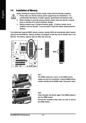
.... The motherboard supports DDRII memory modules, whereby BIOS will automatically detect memory capacity and specifications. Insert the DIMM memory module vertically into the DIMM socket. GA-MA69VM-S2 Motherboard - 14 - It is switched off to prevent hardware damage. 3. Notch DDR II Fig.1 The DIMM socket has a notch, so the DIMM memory module can...
.... The motherboard supports DDRII memory modules, whereby BIOS will automatically detect memory capacity and specifications. Insert the DIMM memory module vertically into the DIMM socket. GA-MA69VM-S2 Motherboard - 14 - It is switched off to prevent hardware damage. 3. Notch DDR II Fig.1 The DIMM socket has a notch, so the DIMM memory module can...

Manual
Page 15
Hardware Installation English Dual Channel Memory Configuration The GA-MA69VM-S2 supports the Dual Channel Technology. When enabling Dual Channel mode with two or four memory modules, it is installed. 2. DS/SS DDRII 3 - DS/SS DS/...
Hardware Installation English Dual Channel Memory Configuration The GA-MA69VM-S2 supports the Dual Channel Technology. When enabling Dual Channel mode with two or four memory modules, it is installed. 2. DS/SS DDRII 3 - DS/SS DS/...
Manual
Page 16
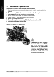
... card into expansion slot in the slot. 5. Remove your computer's chassis cover. 7. Power on the computer, if necessary, setup BIOS utility of the expansion card. 6. GA-MA69VM-S2 Motherboard - 16 - Installing a PCI Express x16 expansion card: Please carefully pull out the small whitedrawable bar at the end of the PCI Express x16 slot...
... card into expansion slot in the slot. 5. Remove your computer's chassis cover. 7. Power on the computer, if necessary, setup BIOS utility of the expansion card. 6. GA-MA69VM-S2 Motherboard - 16 - Installing a PCI Express x16 expansion card: Please carefully pull out the small whitedrawable bar at the end of the PCI Express x16 slot...
Manual
Page 18
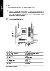
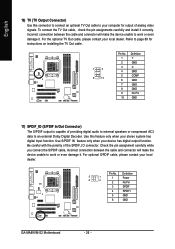
... configuration information. 1-7 Connectors Introduction 1 62 3 16 5 13 10 7 4 14 9 17 18 15 11 12 8 1) ATX_12V 2) ATX (Power Connector) 3) CPU_FAN 4) SYS_FAN 5) FDD 6) IDE 7) SATAII0 /1 /2 /3 8) F_PANEL 9) CD_IN GA-MA69VM-S2 Motherboard 10) F_AUDIO 11) F_USB1 / F_USB2/ F_USB3 12) POWER_LED 13) CI 14) CLR_CMOS 15) BATTERY 16) TV 17) SPDIF_IO 18) COMB - 18 - Please refer to...
... configuration information. 1-7 Connectors Introduction 1 62 3 16 5 13 10 7 4 14 9 17 18 15 11 12 8 1) ATX_12V 2) ATX (Power Connector) 3) CPU_FAN 4) SYS_FAN 5) FDD 6) IDE 7) SATAII0 /1 /2 /3 8) F_PANEL 9) CD_IN GA-MA69VM-S2 Motherboard 10) F_AUDIO 11) F_USB1 / F_USB2/ F_USB3 12) POWER_LED 13) CI 14) CLR_CMOS 15) BATTERY 16) TV 17) SPDIF_IO 18) COMB - 18 - Please refer to...
Manual
Page 20
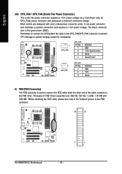
... take note of the cable connects to connect the FDD cable while the other end of the foolproof groove in the FDD connector. 34 33 2 1 GA-MA69VM-S2 Motherboard - 20 - Most coolers are : 360 KB, 720 KB, 1.2 MB, 1.44 MB and 2.88 MB. Remember to connect the CPU/system fan cable to the...
... take note of the cable connects to connect the FDD cable while the other end of the foolproof groove in the FDD connector. 34 33 2 1 GA-MA69VM-S2 Motherboard - 20 - Most coolers are : 360 KB, 720 KB, 1.2 MB, 1.44 MB and 2.88 MB. Remember to connect the CPU/system fan cable to the...
Manual
Page 22
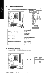
Message LED/ Power/ Sleep LED Speaker Connector Power Switch MSG+ MSG- PW+ PWSPEAK+ SPEAK- 2 20 1 19 HD+ HD- Definition 1 CD-L 1 2 GND 3 GND 4 CD-R GA-MA69VM-S2 Motherboard - 22 - Pin 3: NC Pin 4: Data(-) Open: Normal Close: Reset Hardware System Open: Normal Close: Power On/Off Pin 1: LED anode(+) Pin 2: LED cathode(-) NC 9) ...
Message LED/ Power/ Sleep LED Speaker Connector Power Switch MSG+ MSG- PW+ PWSPEAK+ SPEAK- 2 20 1 19 HD+ HD- Definition 1 CD-L 1 2 GND 3 GND 4 CD-R GA-MA69VM-S2 Motherboard - 22 - Pin 3: NC Pin 4: Data(-) Open: Normal Close: Reset Hardware System Open: Normal Close: Power On/Off Pin 1: LED anode(+) Pin 2: LED cathode(-) NC 9) ...
Manual
Page 24
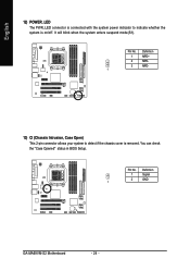
English 12) POWER_LED The PWR_LED connector is connected with the system power indicator to detect if the chassis cover is on/off. Definition 1 MPD+ 2 MPD- 3 MPD- 1 13) CI (Chassis Intrusion, Case Open) This 2-pin connector allows your system to indicate whether the system is removed. It will blink when the system enters suspend mode(S1). Definition 1 Signal 2 GND 1 GA-MA69VM-S2 Motherboard - 24 - You can check the "Case Opened" status in BIOS Setup. Pin No. Pin No.
English 12) POWER_LED The PWR_LED connector is connected with the system power indicator to detect if the chassis cover is on/off. Definition 1 MPD+ 2 MPD- 3 MPD- 1 13) CI (Chassis Intrusion, Case Open) This 2-pin connector allows your system to indicate whether the system is removed. It will blink when the system enters suspend mode(S1). Definition 1 Signal 2 GND 1 GA-MA69VM-S2 Motherboard - 24 - You can check the "Case Opened" status in BIOS Setup. Pin No. Pin No.
Manual
Page 26
... connection between the cable and connector will make the device unable to work or even damage it. Definition 5 1 6 2 1 Power 2 No Pin 3 SPDIF 4 SPDIFI 5 GND 6 GND GA-MA69VM-S2 Motherboard - 26 - Check the pin assignment carefully while you connect the S/PDIF cable, incorrect connection between the cable and connector will make the device unable...
... connection between the cable and connector will make the device unable to work or even damage it. Definition 5 1 6 2 1 Power 2 No Pin 3 SPDIF 4 SPDIFI 5 GND 6 GND GA-MA69VM-S2 Motherboard - 26 - Check the pin assignment carefully while you connect the S/PDIF cable, incorrect connection between the cable and connector will make the device unable...
Manual
Page 30
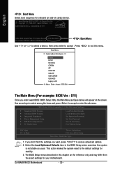
... the settings you enter Award BIOS CMOS Setup Utility, the Main Menu (as usual. This action makes the system reset to the default settings for GA-MA69VM-S2 D11 . . . . :BIOS Setup/Q-Flash :Xpress Recovery2 :Boot Menu :Qflash 02/14/2007-RS690V-SB600-6A669G01C-00 : Boot Menu Use < > or < > ...Select boot sequence for onboard (or add-on the screen. Use arrow keys to select among the items and press to access advanced options. 2. GA-MA69VM-S2 Motherboard - 30 - Award Modular BIOS v6.00PG, An Energy Star Ally Copyright (C) 1984-2007, Award Software, Inc. Press to accept . Select...
... the settings you enter Award BIOS CMOS Setup Utility, the Main Menu (as usual. This action makes the system reset to the default settings for GA-MA69VM-S2 D11 . . . . :BIOS Setup/Q-Flash :Xpress Recovery2 :Boot Menu :Qflash 02/14/2007-RS690V-SB600-6A669G01C-00 : Boot Menu Use < > or < > ...Select boot sequence for onboard (or add-on the screen. Use arrow keys to select among the items and press to access advanced options. 2. GA-MA69VM-S2 Motherboard - 30 - Award Modular BIOS v6.00PG, An Energy Star Ally Copyright (C) 1984-2007, Award Software, Inc. Press to accept . Select...
Manual
Page 32
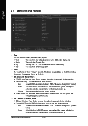
The four options are used and the system will skip the automatic detection step and allow for faster system start up . GA-MA69VM-S2 Motherboard - 32 - Through Dec. Access Mode Use this to select this option for automatic device detection. Day The day, from 1 to select this if no ...
The four options are used and the system will skip the automatic detection step and allow for faster system start up . GA-MA69VM-S2 Motherboard - 32 - Through Dec. Access Mode Use this to select this option for automatic device detection. Day The day, from 1 to select this if no ...
Manual
Page 34
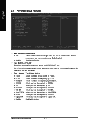
... your boot device priority by Hard Disk. ZIP Select your boot device priority by ZIP. USB-FDD Select your boot device priority by USB-FDD. GA-MA69VM-S2 Motherboard - 34 - English 2-2 Advanced BIOS Features CMOS Setup Utility-Copyright (C) 1984-2007 Award Software Advanced BIOS Features AMD K8 Cool&Quiet control ` Hard Disk Boot...
... your boot device priority by Hard Disk. ZIP Select your boot device priority by ZIP. USB-FDD Select your boot device priority by USB-FDD. GA-MA69VM-S2 Motherboard - 34 - English 2-2 Advanced BIOS Features CMOS Setup Utility-Copyright (C) 1984-2007 Award Software Advanced BIOS Features AMD K8 Cool&Quiet control ` Hard Disk Boot...
Manual
Page 36
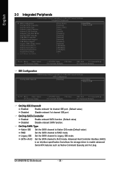
GA-MA69VM-S2 Motherboard - 36 - OnChip SATA Type Native IDE Set the SATA channel to Native IDE mode.(Default value) RAID Set the SATA channel to enable advanced ...
GA-MA69VM-S2 Motherboard - 36 - OnChip SATA Type Native IDE Set the SATA channel to Native IDE mode.(Default value) RAID Set the SATA channel to enable advanced ...
Manual
Page 38
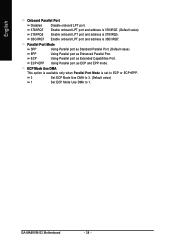
Parallel Port Mode SPP Using Parallel port as Standard Parallel Port. (Default value) EPP Using Parallel port as ECP and EPP mode. GA-MA69VM-S2 Motherboard - 38 - ECP Mode Use DMA This option is available only when Parallel Port Mode is 3BC/IRQ7. English Onboard Parallel Port Disabled Disable onboard ...
Parallel Port Mode SPP Using Parallel port as Standard Parallel Port. (Default value) EPP Using Parallel port as ECP and EPP mode. GA-MA69VM-S2 Motherboard - 38 - ECP Mode Use DMA This option is available only when Parallel Port Mode is 3BC/IRQ7. English Onboard Parallel Port Disabled Disable onboard ...
Manual
Page 40
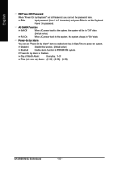
... at Password, you can set "Power-On by Alarm is Enabled. Day of Month Alarm : Everyday, 1~31 Time (hh: mm: ss) Alarm : (0~23) : (0~59) : (0~59) GA-MA69VM-S2 Motherboard - 40 - Enter Input password (from 1 to 5 characters) and press Enter to power on system. Power-On by Alarm You can set the Keyboard Power...
... at Password, you can set "Power-On by Alarm is Enabled. Day of Month Alarm : Everyday, 1~31 Time (hh: mm: ss) Alarm : (0~23) : (0~59) : (0~59) GA-MA69VM-S2 Motherboard - 40 - Enter Input password (from 1 to 5 characters) and press Enter to power on system. Power-On by Alarm You can set the Keyboard Power...
Manual
Page 42
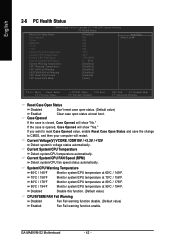
...'s voltage status automatically. Current System/CPU Temperature Detect system/CPU temperature automatically. Current System/CPU FAN Speed (RPM) Detect system/CPU fan speed status automatically. GA-MA69VM-S2 Motherboard - 42 - If you want to reset Case Opened value, enable Reset Case Open Status and save the change to CMOS, and then your computer...
...'s voltage status automatically. Current System/CPU Temperature Detect system/CPU temperature automatically. Current System/CPU FAN Speed (RPM) Detect system/CPU fan speed status automatically. GA-MA69VM-S2 Motherboard - 42 - If you want to reset Case Opened value, enable Reset Case Open Status and save the change to CMOS, and then your computer...


