Manual
Page 4
... ...6 GA-MA69VM-S2 Motherboard Layout 7 Block Diagram ...8 Chapter 1 Hardware Installation 9 1-1 Considerations Prior to Installation 9 1-2 Feature Summary 10 1-3 Installation of the CPU and CPU Cooler 12 1-3-1 Installation of the CPU 12 1-3-2 Installation of the CPU cooler 13 1-4 Installation of Memory 14 1-5 Installation of Expansion Cards 16 1-6 I/O Back Panel Introduction 17 1-7 Connectors Introduction 18 Chapter 2 BIOS Setup 29 The Main Menu (For example: BIOS Ver. : D11 30 2-1 Standard CMOS Features 32 2-2 Advanced BIOS Features 34 2-3 IntegratedPeripherals 36 2-4 Power...
... ...6 GA-MA69VM-S2 Motherboard Layout 7 Block Diagram ...8 Chapter 1 Hardware Installation 9 1-1 Considerations Prior to Installation 9 1-2 Feature Summary 10 1-3 Installation of the CPU and CPU Cooler 12 1-3-1 Installation of the CPU 12 1-3-2 Installation of the CPU cooler 13 1-4 Installation of Memory 14 1-5 Installation of Expansion Cards 16 1-6 I/O Back Panel Introduction 17 1-7 Connectors Introduction 18 Chapter 2 BIOS Setup 29 The Main Menu (For example: BIOS Ver. : D11 30 2-1 Standard CMOS Features 32 2-2 Advanced BIOS Features 34 2-3 IntegratedPeripherals 36 2-4 Power...
Manual
Page 10
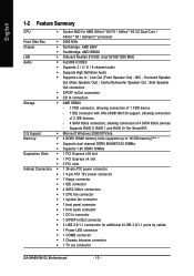
...Out connection Š S/PDIF In/Out connection Š CD In connection Storage Š AMD SB600 - 1 FDD connector, allowing connection of 1 FDD device - 1 IDE connector with ATA-33/66/100/133 support, allowing connection of 2 IDE devices - 4 SATA 3Gb/s connectors, allowing connection of 4 SATA 3Gb/s devices - Line Out (Front Speaker Out) ; English 1-2 Feature Summary CPU Š Socket AM2 for additional 6 USB 2.0/1.1 ports by cables Š 1 Power LED connector Š 1 COMB connector Š 1 Chassis Intrusion connector Š 1 TV out connector GA-MA69VM-S2 Motherboard...
...Out connection Š S/PDIF In/Out connection Š CD In connection Storage Š AMD SB600 - 1 FDD connector, allowing connection of 1 FDD device - 1 IDE connector with ATA-33/66/100/133 support, allowing connection of 2 IDE devices - 4 SATA 3Gb/s connectors, allowing connection of 4 SATA 3Gb/s devices - Line Out (Front Speaker Out) ; English 1-2 Feature Summary CPU Š Socket AM2 for additional 6 USB 2.0/1.1 ports by cables Š 1 Power LED connector Š 1 COMB connector Š 1 Chassis Intrusion connector Š 1 TV out connector GA-MA69VM-S2 Motherboard...

Manual
Page 15
... be used and installed in DDRII 1 and DDRII 2 DIMM sockets. - 15 - Dual Channel mode cannot be used to operate the Dual Channel Technology, follow the guidelines below: 1. DS/SS DDRII 2 DS/SS - English Dual Channel Memory Configuration The GA-MA69VM-S2 supports the Dual Channel Technology. When enabling Dual Channel mode with two or four memory modules, it is recommended that memory of Memory Bus will add double. Hardware Installation Due to CPU limitation, if you wish to achieve Dual Channel mode, we recommend installing...
... be used and installed in DDRII 1 and DDRII 2 DIMM sockets. - 15 - Dual Channel mode cannot be used to operate the Dual Channel Technology, follow the guidelines below: 1. DS/SS DDRII 2 DS/SS - English Dual Channel Memory Configuration The GA-MA69VM-S2 supports the Dual Channel Technology. When enabling Dual Channel mode with two or four memory modules, it is recommended that memory of Memory Bus will add double. Hardware Installation Due to CPU limitation, if you wish to achieve Dual Channel mode, we recommend installing...
Manual
Page 18
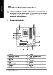
... 2-/4-/6-/8- In addition to the default speakers settings, the ~ audio jacks can be connected to perform different functions via the audio software. Only microphones still MUST be reconfigured to the default Mic In jack ( ). channel audio setup steps for detailed software configuration information. 1-7 Connectors Introduction 1 62 3 16 5 13 10 7 4 14 9 17 18 15 11 12 8 1) ATX_12V 2) ATX (Power Connector) 3) CPU_FAN 4) SYS_FAN 5) FDD 6) IDE 7) SATAII0 /1 /2 /3 8) F_PANEL 9) CD_IN GA-MA69VM-S2 Motherboard 10) F_AUDIO 11...
... 2-/4-/6-/8- In addition to the default speakers settings, the ~ audio jacks can be connected to perform different functions via the audio software. Only microphones still MUST be reconfigured to the default Mic In jack ( ). channel audio setup steps for detailed software configuration information. 1-7 Connectors Introduction 1 62 3 16 5 13 10 7 4 14 9 17 18 15 11 12 8 1) ATX_12V 2) ATX (Power Connector) 3) CPU_FAN 4) SYS_FAN 5) FDD 6) IDE 7) SATAII0 /1 /2 /3 8) F_PANEL 9) CD_IN GA-MA69VM-S2 Motherboard 10) F_AUDIO 11...
Manual
Page 20
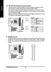
... Fan Power Connector) The cooler fan power connector supplies a +12V power voltage via a 3-pin/4-pin (only for CPU_FAN) power connector and possesses a foolproof connection design. The types of FDD drives supported are designed with color-coded power connector wires. Before attaching the FDD cable, please take note of the cable connects to connect the FDD cable while the other end of the foolproof groove in the FDD connector. 34 33 2 1 GA-MA69VM-S2 Motherboard - 20 - A red power connector wire indicates a positive connection and requires a +12V power voltage...
... Fan Power Connector) The cooler fan power connector supplies a +12V power voltage via a 3-pin/4-pin (only for CPU_FAN) power connector and possesses a foolproof connection design. The types of FDD drives supported are designed with color-coded power connector wires. Before attaching the FDD cable, please take note of the cable connects to connect the FDD cable while the other end of the foolproof groove in the FDD connector. 34 33 2 1 GA-MA69VM-S2 Motherboard - 20 - A red power connector wire indicates a positive connection and requires a +12V power voltage...

Manual
Page 21
... Installation English 6) IDE (IDE Connector) An IDE device connects to 300 MB/s transfer rate. One IDE connector can connect to one IDE device as Master and the other as Slave (for the Serial ATA and install the proper driver in the IDE connector. 40 39 2 1 7) SATAII0 /1 /2 /3 (SATA 3Gb/s Connectors, Controlled by AMD SB600) SATA 3Gb/s can then connect to work properly. 7 1 SATAII 2 Pin No. Please refer to the BIOS setting for information on settings, please refer to the instructions located...
... Installation English 6) IDE (IDE Connector) An IDE device connects to 300 MB/s transfer rate. One IDE connector can connect to one IDE device as Master and the other as Slave (for the Serial ATA and install the proper driver in the IDE connector. 40 39 2 1 7) SATAII0 /1 /2 /3 (SATA 3Gb/s Connectors, Controlled by AMD SB600) SATA 3Gb/s can then connect to work properly. 7 1 SATAII 2 Pin No. Please refer to the BIOS setting for information on settings, please refer to the instructions located...
Manual
Page 22
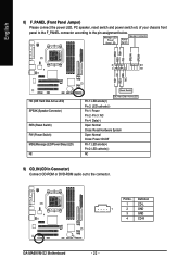
... CD-R GA-MA69VM-S2 Motherboard - 22 - Pin No. Message LED/ Power/ Sleep LED Speaker Connector Power Switch MSG+ MSG- RESRES+ NC HD (IDE Hard Disk Active LED) SPEAK (Speaker Connector) RES (Reset Switch) PW (Power Switch) MSG(Message LED/Power/Sleep LED) NC Reset Switch IDE Hard Disk Active LED Pin 1: LED anode(+) Pin 2: LED cathode(-) Pin 1: Power Pin 2- Pin 3: NC Pin 4: Data(-) Open: Normal Close: Reset Hardware System Open: Normal Close: Power On/Off Pin 1: LED anode(+) Pin 2: LED cathode(-) NC 9) CD_IN (CD In Connector) Connect CD-ROM or DVD-ROM audio out to the pin assignment...
... CD-R GA-MA69VM-S2 Motherboard - 22 - Pin No. Message LED/ Power/ Sleep LED Speaker Connector Power Switch MSG+ MSG- RESRES+ NC HD (IDE Hard Disk Active LED) SPEAK (Speaker Connector) RES (Reset Switch) PW (Power Switch) MSG(Message LED/Power/Sleep LED) NC Reset Switch IDE Hard Disk Active LED Pin 1: LED anode(+) Pin 2: LED cathode(-) Pin 1: Power Pin 2- Pin 3: NC Pin 4: Data(-) Open: Normal Close: Reset Hardware System Open: Normal Close: Power On/Off Pin 1: LED anode(+) Pin 2: LED cathode(-) NC 9) CD_IN (CD In Connector) Connect CD-ROM or DVD-ROM audio out to the pin assignment...
Manual
Page 30
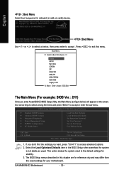
...: Save & Exit Setup Time, Date, Hard Disk Type... 1. If you don't find the settings you enter Award BIOS CMOS Setup Utility, the Main Menu (as usual. GA-MA69VM-S2 Motherboard - 30 - The BIOS Setup menus described in the BIOS Setup when somehow the system is not stable as figure below) will appear on cards) device. Boot Menu == Select a Boot First device == Floppy LS120 Hard Disk CDROM ZIP USB-FDD USB-ZIP USB-CDROM USB-HDD Legacy LAN KL:Move Enter :Accept ESC:Exit The Main Menu (For example: BIOS Ver. : D11...
...: Save & Exit Setup Time, Date, Hard Disk Type... 1. If you don't find the settings you enter Award BIOS CMOS Setup Utility, the Main Menu (as usual. GA-MA69VM-S2 Motherboard - 30 - The BIOS Setup menus described in the BIOS Setup when somehow the system is not stable as figure below) will appear on cards) device. Boot Menu == Select a Boot First device == Floppy LS120 Hard Disk CDROM ZIP USB-FDD USB-ZIP USB-CDROM USB-HDD Legacy LAN KL:Move Enter :Accept ESC:Exit The Main Menu (For example: BIOS Ver. : D11...
Manual
Page 32
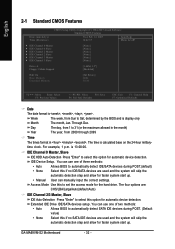
.... IDE Device Setup. GA-MA69VM-S2 Motherboard - 32 - English 2-1 Standard CMOS Features Date (mm:dd:yy) Time (hh:mm:ss) CMOS Setup Utility-Copyright (C) 1984-2007 Award Software Standard CMOS Features Wed, Feb 14 2007 14:42:37 Item Help Menu Level` ` IDE Channel 0 Master ` IDE Channel 0 Slave ` IDE Channel 2 Master ` IDE Channel 2 Slave ` IDE Channel 3 Master ` IDE Channel 3 Slave [None] [None] [None] [None] [None] [None] Drive A Floppy 3 Mode Support [1.44M, 3.5"] [Disabled] Halt On Base Memory Extended Memory [All Errors] 640K 511M KLJI: Move Enter: Select...
.... IDE Device Setup. GA-MA69VM-S2 Motherboard - 32 - English 2-1 Standard CMOS Features Date (mm:dd:yy) Time (hh:mm:ss) CMOS Setup Utility-Copyright (C) 1984-2007 Award Software Standard CMOS Features Wed, Feb 14 2007 14:42:37 Item Help Menu Level` ` IDE Channel 0 Master ` IDE Channel 0 Slave ` IDE Channel 2 Master ` IDE Channel 2 Slave ` IDE Channel 3 Master ` IDE Channel 3 Slave [None] [None] [None] [None] [None] [None] Drive A Floppy 3 Mode Support [1.44M, 3.5"] [Disabled] Halt On Base Memory Extended Memory [All Errors] 640K 511M KLJI: Move Enter: Select...
Manual
Page 34
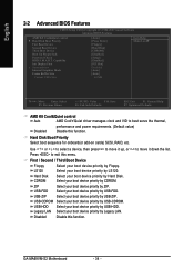
... device priority by Floppy. Hard Disk Select your boot device priority by Hard Disk. Legacy LAN Select your boot device priority by Legacy LAN. GA-MA69VM-S2 Motherboard - 34 - Use < > or < > to select a device, then press to move it down the list. English 2-2 Advanced BIOS Features CMOS Setup Utility-Copyright (C) 1984-2007 Award Software Advanced BIOS Features AMD K8 Cool&Quiet control ` Hard Disk Boot Priority First Boot Device Second Boot Device Third Boot Device Boot Up Floopy Seek Password Check HDD S.M.A.R.T. Hard Disk Boot Priority Select boot sequence for onboard...
... device priority by Floppy. Hard Disk Select your boot device priority by Hard Disk. Legacy LAN Select your boot device priority by Legacy LAN. GA-MA69VM-S2 Motherboard - 34 - Use < > or < > to select a device, then press to move it down the list. English 2-2 Advanced BIOS Features CMOS Setup Utility-Copyright (C) 1984-2007 Award Software Advanced BIOS Features AMD K8 Cool&Quiet control ` Hard Disk Boot Priority First Boot Device Second Boot Device Third Boot Device Boot Up Floopy Seek Password Check HDD S.M.A.R.T. Hard Disk Boot Priority Select boot sequence for onboard...

Manual
Page 35
... motherboard. Disabled Enabled Disable the Dual-View capability. (Default value) Enable the Dual-View capability. Note that BIOS can not access to select the first initiation of floppy disk drive by track number. Enabled Enable HDD S.M.A.R.T. When a PCI Express card is installed, automatically output from 720K, 1.2M or 1.44M drive type as they are all 80 tracks. BIOS Setup Set Init Display First to PCI VGA card. (Default value) OnChip VGA Set Init Display First to 1024 MB. Set frame buffer size to onboard VGA. English Boot Up Floppy...
... motherboard. Disabled Enabled Disable the Dual-View capability. (Default value) Enable the Dual-View capability. Note that BIOS can not access to select the first initiation of floppy disk drive by track number. Enabled Enable HDD S.M.A.R.T. When a PCI Express card is installed, automatically output from 720K, 1.2M or 1.44M drive type as they are all 80 tracks. BIOS Setup Set Init Display First to PCI VGA card. (Default value) OnChip VGA Set Init Display First to 1024 MB. Set frame buffer size to onboard VGA. English Boot Up Floppy...
Manual
Page 36
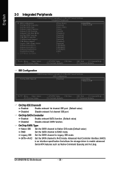
... plug. GA-MA69VM-S2 Motherboard - 36 - OnChip SATA Controller Enabled Enable onboard SATA function. (Default value) Disabled Disable onboard SATA function. Advanced Host Controller Interface (AHCI) is an interface specification that allows the storage driver to Legacy IDE mode. English 2-3 Integrated Peripherals CMOS Setup Utility-Copyright (C) 1984-2007 Award Software Integrated Peripherals ` IDE Configuration OnChip SATA Controller OnChip SATA Type Onboard Audio Function Onboard LAN Function Onboard LAN Boot ROM OnChip USB Controller USB EHCI Controller USB Keyboard...
... plug. GA-MA69VM-S2 Motherboard - 36 - OnChip SATA Controller Enabled Enable onboard SATA function. (Default value) Disabled Disable onboard SATA function. Advanced Host Controller Interface (AHCI) is an interface specification that allows the storage driver to Legacy IDE mode. English 2-3 Integrated Peripherals CMOS Setup Utility-Copyright (C) 1984-2007 Award Software Integrated Peripherals ` IDE Configuration OnChip SATA Controller OnChip SATA Type Onboard Audio Function Onboard LAN Function Onboard LAN Boot ROM OnChip USB Controller USB EHCI Controller USB Keyboard...

Manual
Page 37
... 1 Auto BIOS will automatically setup the port 1 address. 3F8/IRQ4 Enable onboard Serial port 1 and address is 3F8/IRQ4. (Default value) 2F8/IRQ3 Enable onboard Serial port 1 and address is 2F8/IRQ3. 3E8/IRQ4 2E8/IRQ3 Enable onboard Serial port 1 and address is 3E8/IRQ4. USB EHCI Controller Enable Enable USB 2.0 function. (Default Value) Disabled Disable onchip USB 2.0 function. BIOS Setup Onboard LAN Boot ROM This function decide whether to detect USB storage devices, including USB flash drives and USB hard drives during POST. Disabled Disable USB keyboard support...
... 1 Auto BIOS will automatically setup the port 1 address. 3F8/IRQ4 Enable onboard Serial port 1 and address is 3F8/IRQ4. (Default value) 2F8/IRQ3 Enable onboard Serial port 1 and address is 2F8/IRQ3. 3E8/IRQ4 2E8/IRQ3 Enable onboard Serial port 1 and address is 3E8/IRQ4. USB EHCI Controller Enable Enable USB 2.0 function. (Default Value) Disabled Disable onchip USB 2.0 function. BIOS Setup Onboard LAN Boot ROM This function decide whether to detect USB storage devices, including USB flash drives and USB hard drives during POST. Disabled Disable USB keyboard support...

Manual
Page 45
... or any time you can enter Setup freely. A message "PASSWORD DISABLED" will boot and you try to enter Setup. - 45 - The BIOS Setup program allows you in creating a password. BIOS Setup English 2-9 Set Supervisor/User Password CMOS Setup Utility-Copyright (C) 1984-2007 Award Software ` Standard CMOS Features ` Advanced BIOS Features ` Integrated Peripherals ` Power Management Setup ` PnP/PCI ConfiguratioEnsnter Password: ` PC Health Status Load Fail-Safe Defaults Load Optimized Defaults Set Supervisor Password Set User Password Save & Exit Setup Exit Without Saving Esc: Quit...
... or any time you can enter Setup freely. A message "PASSWORD DISABLED" will boot and you try to enter Setup. - 45 - The BIOS Setup program allows you in creating a password. BIOS Setup English 2-9 Set Supervisor/User Password CMOS Setup Utility-Copyright (C) 1984-2007 Award Software ` Standard CMOS Features ` Advanced BIOS Features ` Integrated Peripherals ` Power Management Setup ` PnP/PCI ConfiguratioEnsnter Password: ` PC Health Status Load Fail-Safe Defaults Load Optimized Defaults Set Supervisor Password Set User Password Save & Exit Setup Exit Without Saving Esc: Quit...
Manual
Page 52
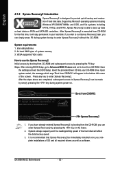
... enter Xpress Recovery2. GA-M69VM-S2 Motherboard - 52 - Intel x86 platforms 2. Save the settings and exit the BIOS Setup. Upon system restart, the message which says "Boot from the CD-ROM, you complete installations of system memory 3. Press any key to startup XpressRecovery2..... After the steps above are completed, subsequent access to Xpress Recovery2 can simply press F9 during system power-on PATA and SATA IDE controllers. Supporting...
... enter Xpress Recovery2. GA-M69VM-S2 Motherboard - 52 - Intel x86 platforms 2. Save the settings and exit the BIOS Setup. Upon system restart, the message which says "Boot from the CD-ROM, you complete installations of system memory 3. Press any key to startup XpressRecovery2..... After the steps above are completed, subsequent access to Xpress Recovery2 can simply press F9 during system power-on PATA and SATA IDE controllers. Supporting...
Manual
Page 54
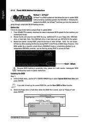
... End key during POST or the F8 key in RAID/AHCI mode or a hard drive attached to an independent IDE/SATA controller, use FAT32/16/12 file system. 3. However, if the BIOS update file is saved to a hard drive in BIOS Setup. If you from the hassles of going through complicated BIOS flashing process. Extract the file and save the new BIOS file (e.g. ma69vms2.F1) to your motherboard model. 2. Restart the system. AMD RS690 BIOS for GA-MA69VM-S2 D11 . . . . :BIOS Setup/Q-Flash :Xpress Recovery2 :Boot Menu...
... End key during POST or the F8 key in RAID/AHCI mode or a hard drive attached to an independent IDE/SATA controller, use FAT32/16/12 file system. 3. However, if the BIOS update file is saved to a hard drive in BIOS Setup. If you from the hassles of going through complicated BIOS flashing process. Extract the file and save the new BIOS file (e.g. ma69vms2.F1) to your motherboard model. 2. Restart the system. AMD RS690 BIOS for GA-MA69VM-S2 D11 . . . . :BIOS Setup/Q-Flash :Xpress Recovery2 :Boot Menu...

Manual
Page 65
... to install the SATA controller driver during the Windows setup process. At the D:\> prompt, type the following two commands. Figure 10 Figure 11 (Note) For users without a startup disk: Use an alternative system and insert the GIGABYTE motherboard driver CD-ROM. Once at the A:\> prompt, change to a floppy disk. Without the driver, the hard disk may not be recognized during OS installation. First of all, copy the driver for the SATA controller from the menu...
... to install the SATA controller driver during the Windows setup process. At the D:\> prompt, type the following two commands. Figure 10 Figure 11 (Note) For users without a startup disk: Use an alternative system and insert the GIGABYTE motherboard driver CD-ROM. Once at the A:\> prompt, change to a floppy disk. Without the driver, the hard disk may not be recognized during OS installation. First of all, copy the driver for the SATA controller from the menu...
Manual
Page 66
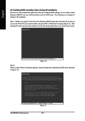
... special disk controllers for use with Windows, including those for use with the SATA driver. English (5) Installing SATA controller driver during OS installation Now that below appears, insert the floppy disk containing the SATA driver and press S (Figure 14). Figure 13 Step 2: When a screen similar to that you have prepared the SATA driver disk and configured BIOS settings, you are ready to install Windows 2000/XP onto your system, or you have any device support disks from a mass storage device...
... special disk controllers for use with Windows, including those for use with the SATA driver. English (5) Installing SATA controller driver during OS installation Now that below appears, insert the floppy disk containing the SATA driver and press S (Figure 14). Figure 13 Step 2: When a screen similar to that you have prepared the SATA driver disk and configured BIOS settings, you are ready to install Windows 2000/XP onto your system, or you have any device support disks from a mass storage device...

Manual
Page 70
... Peripherals ` Power Management Setup ` PnP/PCI Configurations ` PC Health Status Load Fail-Safe Defaults Load Optimized Defaults Set Supervisor Password Set User Password Save & Exit Setup Exit Without Saving ESC: Quit F8: Q-Flash KLJI: Select Item F10: Save & Exit Setup Time, Date, Hard Disk Type... Then In IGX Configuration press . CMOS Setup Utility-Copyright (C) 1984-2007 Award Software Advanced Chipset Features ` DRAM Configuration ` LDT & PCI Bus Control ` PCIE Configuration ` IGX Configuration [Press Enter] [Press Enter] [Press Enter] [Press Enter] Item Help Menu Level` SB600...
... Peripherals ` Power Management Setup ` PnP/PCI Configurations ` PC Health Status Load Fail-Safe Defaults Load Optimized Defaults Set Supervisor Password Set User Password Save & Exit Setup Exit Without Saving ESC: Quit F8: Q-Flash KLJI: Select Item F10: Save & Exit Setup Time, Date, Hard Disk Type... Then In IGX Configuration press . CMOS Setup Utility-Copyright (C) 1984-2007 Award Software Advanced Chipset Features ` DRAM Configuration ` LDT & PCI Bus Control ` PCIE Configuration ` IGX Configuration [Press Enter] [Press Enter] [Press Enter] [Press Enter] Item Help Menu Level` SB600...

Manual
Page 78
... the possible computer problems. However, they are using is equipped with power/amplifier and try again later. Please press Ctrl and F1 keys after turning up . J AWARD BIOS Beep Codes 1 short: System boots successfully 2 short: CMOS setting error 1 long 1 short: DRAM or M/B error 1 long 2 short: Monitor or display card error 1 long 3 short: Keyboard error 1 long 9 short: BIOS ROM error Continuous long beeps: DRAM error Continuous short beeps: Power error GA-M69VM-S2 Motherboard - 78 - Answer: Some advanced options are hidden in the battery holder to see some boards, a small amount of...
... the possible computer problems. However, they are using is equipped with power/amplifier and try again later. Please press Ctrl and F1 keys after turning up . J AWARD BIOS Beep Codes 1 short: System boots successfully 2 short: CMOS setting error 1 long 1 short: DRAM or M/B error 1 long 2 short: Monitor or display card error 1 long 3 short: Keyboard error 1 long 9 short: BIOS ROM error Continuous long beeps: DRAM error Continuous short beeps: Power error GA-M69VM-S2 Motherboard - 78 - Answer: Some advanced options are hidden in the battery holder to see some boards, a small amount of...


