Manual
Page 4
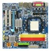
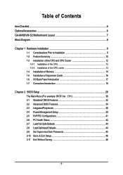
Table of Contents ItemChecklist ...6 OptionalAccessories ...6 GA-MA69VM-S2 Motherboard Layout 7 Block Diagram ...8 Chapter 1 Hardware Installation 9 1-1 Considerations Prior to Installation 9 1-2 Feature Summary 10 1-3 Installation of the CPU and CPU Cooler 12 1-3-1 Installation of the CPU 12 1-3-2 Installation of the CPU cooler 13 1-4 Installation of Memory 14 1-5 Installation of Expansion Cards 16 1-6 I/O Back Panel Introduction 17 1-7 Connectors Introduction 18 Chapter...
Table of Contents ItemChecklist ...6 OptionalAccessories ...6 GA-MA69VM-S2 Motherboard Layout 7 Block Diagram ...8 Chapter 1 Hardware Installation 9 1-1 Considerations Prior to Installation 9 1-2 Feature Summary 10 1-3 Installation of the CPU and CPU Cooler 12 1-3-1 Installation of the CPU 12 1-3-2 Installation of the CPU cooler 13 1-4 Installation of Memory 14 1-5 Installation of Expansion Cards 16 1-6 I/O Back Panel Introduction 17 1-7 Connectors Introduction 18 Chapter...
Manual
Page 9
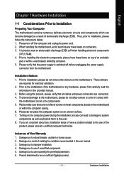
... Before using the product, please verify that the power supply is best to wear an electrostatic discharge (ESD) cuff when handling electronic components (CPU, RAM). 4. Please make sure there are connected. 4. Turning on the motherboard or within a electrostatic shielding container. 5. If you are required... which can lead to damage to system components as well as a result of electrostatic discharge (ESD). Thus, prior to be an unofficial Gigabyte product. - 9 - It is switched off the computer and unplug its components. 5. Prior to installing the electronic components, please have...
... Before using the product, please verify that the power supply is best to wear an electrostatic discharge (ESD) cuff when handling electronic components (CPU, RAM). 4. Please make sure there are connected. 4. Turning on the motherboard or within a electrostatic shielding container. 5. If you are required... which can lead to damage to system components as well as a result of electrostatic discharge (ESD). Thus, prior to be an unofficial Gigabyte product. - 9 - It is switched off the computer and unplug its components. 5. Prior to installing the electronic components, please have...
Manual
Page 10
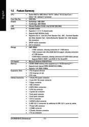
...; 1 4-pin ATX 12V power connector Š 1 floppy connector Š 1 IDE connector Š 4 SATA 3Gb/s connectors Š 1 CPU fan connector Š 1 system fan connector Š 1 front panel connector Š 1 front audio connector Š 1 CD In connector Š... Audio Š Supports Line In ; English 1-2 Feature Summary CPU Š Socket AM2 for additional 6 USB 2.0/1.1 ports by cables Š 1 Power LED connector Š 1 COMB connector Š 1 Chassis Intrusion connector Š 1 TV out connector GA-MA69VM-S2 Motherboard - 10 - Line Out (Front Speaker Out) ;...
...; 1 4-pin ATX 12V power connector Š 1 floppy connector Š 1 IDE connector Š 4 SATA 3Gb/s connectors Š 1 CPU fan connector Š 1 system fan connector Š 1 front panel connector Š 1 front audio connector Š 1 CD In connector Š... Audio Š Supports Line In ; English 1-2 Feature Summary CPU Š Socket AM2 for additional 6 USB 2.0/1.1 ports by cables Š 1 Power LED connector Š 1 COMB connector Š 1 Chassis Intrusion connector Š 1 TV out connector GA-MA69VM-S2 Motherboard - 10 - Line Out (Front Speaker Out) ;...

Manual
Page 11
... Out) I/O Control Š IT8716 chip Hardware Monitor Š System voltage detection Š CPU / System temperature detection Š CPU / System fan speed detection Š CPU / System warning temperature Š CPU / System fan failure warning Š Supports CPU Smart Fan function(Note 2) BIOS Š 1 4 Mbit flash ROM Š Use of... is supported will be less than 4 GB; Windows 64-bit operating system doesn't have such limitation. (Note 2) Whether the CPU Smart FAN Control function is installed, the actual memory available for the operating system will depend on the...
... Out) I/O Control Š IT8716 chip Hardware Monitor Š System voltage detection Š CPU / System temperature detection Š CPU / System fan speed detection Š CPU / System warning temperature Š CPU / System fan failure warning Š Supports CPU Smart Fan function(Note 2) BIOS Š 1 4 Mbit flash ROM Š Use of... is supported will be less than 4 GB; Windows 64-bit operating system doesn't have such limitation. (Note 2) Whether the CPU Smart FAN Control function is installed, the actual memory available for the operating system will depend on the...
Manual
Page 12
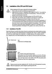
... and gently lower it does not meet the required standards for the peripherals. If you wish to set the CPU host frequency in the wrong direction, the CPU will not fit if positioned incorrectly. GA-MA69VM-S2 Motherboard - 12 - Please set the frequency beyond hardware specifica tions since it into position making sure that the...
... and gently lower it does not meet the required standards for the peripherals. If you wish to set the CPU host frequency in the wrong direction, the CPU will not fit if positioned incorrectly. GA-MA69VM-S2 Motherboard - 12 - Please set the frequency beyond hardware specifica tions since it into position making sure that the...
Manual
Page 13
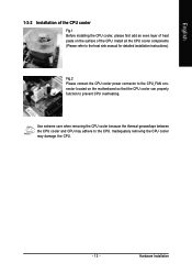
... detailed installation instructions). Use extreme care when removing the CPU cooler because the thermal grease/tape between the CPU cooler and CPU may damage the CPU. - 13 - English 1-3-2 Installation of the CPU cooler Fig.1 Before installing the CPU cooler, please first add an even layer of the CPU. Install all the CPU cooler components (Please refer to the...
... detailed installation instructions). Use extreme care when removing the CPU cooler because the thermal grease/tape between the CPU cooler and CPU may damage the CPU. - 13 - English 1-3-2 Installation of the CPU cooler Fig.1 Before installing the CPU cooler, please first add an even layer of the CPU. Install all the CPU cooler components (Please refer to the...

Manual
Page 15
Due to CPU limitation, if you wish to be used and installed in DDRII 1 and DDRII 2 DIMM sockets. - 15 - DS/SS DDRII 2 DS/SS - DS/SS DDRII 3 - When ... modules, it is recommended that memory of Memory Bus will add double. Hardware Installation DS/SS DS/SS DDRII 4 - English Dual Channel Memory Configuration The GA-MA69VM-S2 supports the Dual Channel Technology. The following is installed. 2. DS/SS DS/SS If two memory modules are to operate the Dual Channel Technology, follow...
Due to CPU limitation, if you wish to be used and installed in DDRII 1 and DDRII 2 DIMM sockets. - 15 - DS/SS DDRII 2 DS/SS - DS/SS DDRII 3 - When ... modules, it is recommended that memory of Memory Bus will add double. Hardware Installation DS/SS DS/SS DDRII 4 - English Dual Channel Memory Configuration The GA-MA69VM-S2 supports the Dual Channel Technology. The following is installed. 2. DS/SS DS/SS If two memory modules are to operate the Dual Channel Technology, follow...
Manual
Page 19
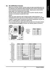
... the power connector with its proper location on the motherboard before plugging in the power cord; The ATX_12V power connector mainly supplies power to the CPU. If you use a 24-pin ATX power supply, please remove the small cover on the power connector on the motherboard and connect tightly. English 1/2) ATX_12V...
... the power connector with its proper location on the motherboard before plugging in the power cord; The ATX_12V power connector mainly supplies power to the CPU. If you use a 24-pin ATX power supply, please remove the small cover on the power connector on the motherboard and connect tightly. English 1/2) ATX_12V...
Manual
Page 20
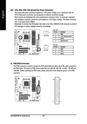
... requires a +12V power voltage. The black connector wire is used to connect the FDD cable while the other end of the cable connects to prevent CPU damage or system hanging caused by overheating. 1 CPU_FAN CPU_FAN : Pin No. 1 2 3 4 Definition GND +12V / Speed Control Sense Speed Control 1 SYS_FAN SYS_FAN : Pin No. 1 2 3 Definition ... note of FDD drives supported are designed with color-coded power connector wires. The types of the foolproof groove in the FDD connector. 34 33 2 1 GA-MA69VM-S2 Motherboard - 20 - Most coolers are : 360 KB, 720 KB, 1.2 MB, 1.44 MB and 2.88 MB.
... requires a +12V power voltage. The black connector wire is used to connect the FDD cable while the other end of the cable connects to prevent CPU damage or system hanging caused by overheating. 1 CPU_FAN CPU_FAN : Pin No. 1 2 3 4 Definition GND +12V / Speed Control Sense Speed Control 1 SYS_FAN SYS_FAN : Pin No. 1 2 3 Definition ... note of FDD drives supported are designed with color-coded power connector wires. The types of the foolproof groove in the FDD connector. 34 33 2 1 GA-MA69VM-S2 Motherboard - 20 - Most coolers are : 360 KB, 720 KB, 1.2 MB, 1.44 MB and 2.88 MB.
Manual
Page 33
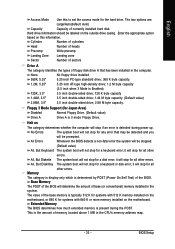
... the motherboard, or 640 K for a keyboard error; The two options are: Large/Auto(default: Auto) Capacity Capacity of base (or conventional) memory installed in the CPU's memory address map. - 33 - None No floppy drive installed 360K, 5.25" 5.25 inch PC-type standard drive; 360 K byte capacity. 1.2M, 5.25" 5.25 inch AT...
... the motherboard, or 640 K for a keyboard error; The two options are: Large/Auto(default: Auto) Capacity Capacity of base (or conventional) memory installed in the CPU's memory address map. - 33 - None No floppy drive installed 360K, 5.25" 5.25 inch PC-type standard drive; 360 K byte capacity. 1.2M, 5.25" 5.25 inch AT...
Manual
Page 42
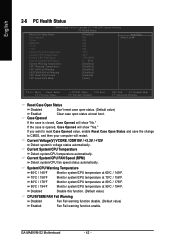
... FAN Fail Warning Disabled Fan Fail warning function disable. (Default value) Enabled Fan Fail warning function enable. GA-MA69VM-S2 Motherboard - 42 - Monitor system/CPU temperature at 80oC / 176oF. 90oC / 194oF Monitor system/CPU temperature at 70oC / 158oF. English 2-6 PC Health Status CMOS Setup Utility-Copyright (C) 1984-2007 Award Software PC Health Status Reset Case...
... FAN Fail Warning Disabled Fan Fail warning function disable. (Default value) Enabled Fan Fail warning function enable. GA-MA69VM-S2 Motherboard - 42 - Monitor system/CPU temperature at 80oC / 176oF. 90oC / 194oF Monitor system/CPU temperature at 70oC / 158oF. English 2-6 PC Health Status CMOS Setup Utility-Copyright (C) 1984-2007 Award Software PC Health Status Reset Case...

Manual
Page 43
When this function. Auto BIOS autodetects the type of CPU fan you installed and sets the optimal CPU Smart FAN control mode for it. (Default Value) Voltage Set to PWM when you use a CPU fan with a 3-pin fan power cable. BIOS Setup PWM Set to Voltage when you install. -... speed depending on their requirements. (Default value) CPU Smart FAN Mode This option is available only when CPU Smart FAN Control is enabled, CPU fan will depend on the CPU you use a CPU fan with Easy Tune based on CPU temperature. English CPU Smart FAN Control (Note) Disabled Enabled Disable this...
When this function. Auto BIOS autodetects the type of CPU fan you installed and sets the optimal CPU Smart FAN control mode for it. (Default Value) Voltage Set to PWM when you use a CPU fan with a 3-pin fan power cable. BIOS Setup PWM Set to Voltage when you install. -... speed depending on their requirements. (Default value) CPU Smart FAN Mode This option is available only when CPU Smart FAN Control is enabled, CPU fan will depend on the CPU you use a CPU fan with Easy Tune based on CPU temperature. English CPU Smart FAN Control (Note) Disabled Enabled Disable this...

Manual
Page 51
... Easy and Advance Mode 7. Appendix Overclocking Enters the Overclocking setting page 2. and M.I .B. Display screen Display panel of both CPU cooling fan and North-Bridge Chipset cooling fan, 4) PC health for enhancing system performance, 2) C.I .B. Function display LEDs Shows ...and M.I .B. GO Confirmation and Execution button 6. GIGABYTE Logo Log on different motherboards. - 51 - C.I .A. Enters the C.I .A. for special enhancement for CPU and Memory, 3) Smart-Fan control for managing fan speed control of CPU frequency 8. Exit or Minimize button Quit or Minimize ...
... Easy and Advance Mode 7. Appendix Overclocking Enters the Overclocking setting page 2. and M.I .B. Display screen Display panel of both CPU cooling fan and North-Bridge Chipset cooling fan, 4) PC health for enhancing system performance, 2) C.I .B. Function display LEDs Shows ...and M.I .B. GO Confirmation and Execution button 6. GIGABYTE Logo Log on different motherboards. - 51 - C.I .A. Enters the C.I .A. for special enhancement for CPU and Memory, 3) Smart-Fan control for managing fan speed control of CPU frequency 8. Exit or Minimize button Quit or Minimize ...

Manual
Page 70
...PD: Value F10: Save F6: Fail-Safe Defaults ESC: Exit F1: General Help F7: Optimized Defaults Step 4:Save and exit BIOS Setup. GA-M69VM-S2 Motherboard - 70 - CMOS Setup Utility-Copyright (C) 1984-2007 Award Software ` Standard CMOS Features ` Advanced BIOS Features ` Integrated Peripherals ` ... Control ` PCIE Configuration ` IGX Configuration [Press Enter] [Press Enter] [Press Enter] [Press Enter] Item Help Menu Level` SB600 Spread Spectrum CPU Clock Ratio CPU Frequency (MHz) [Disabled] [Auto] [Auto] KLJI: Move Enter: Select F5: Previous Values +/-/PU/PD: Value F10: Save F6: Fail-...
...PD: Value F10: Save F6: Fail-Safe Defaults ESC: Exit F1: General Help F7: Optimized Defaults Step 4:Save and exit BIOS Setup. GA-M69VM-S2 Motherboard - 70 - CMOS Setup Utility-Copyright (C) 1984-2007 Award Software ` Standard CMOS Features ` Advanced BIOS Features ` Integrated Peripherals ` ... Control ` PCIE Configuration ` IGX Configuration [Press Enter] [Press Enter] [Press Enter] [Press Enter] Item Help Menu Level` SB600 Spread Spectrum CPU Clock Ratio CPU Frequency (MHz) [Disabled] [Auto] [Auto] KLJI: Move Enter: Select F5: Previous Values +/-/PU/PD: Value F10: Save F6: Fail-...


