
Manual
Page 5
Chapter 3 Drivers Installation 47 3-1 Install Chipset Drivers 47 3-2 SoftwareApplication 48 3-3 Software Information 48 3-4 Hardware Information 49 3-5 Contact Us ...49 Chapter 4 Appendix 51 4-1 Unique Software Utilities 51 4-1-1 EasyTune 5 Introduction 51 4-1-2 Xpress Recovery2 Introduction 52 4-1-3 Flash BIOS Method Introduction 54 4-1-4 Configuring SATA Hard Drive(s 58 4-1-5 Installation of TV Output Cable (Optional Device 69 4-1-6 2- / 4- / 6- / 8- Channel Audio Function Introduction 73 4-2 Troubleshooting 78 - 5 -
Chapter 3 Drivers Installation 47 3-1 Install Chipset Drivers 47 3-2 SoftwareApplication 48 3-3 Software Information 48 3-4 Hardware Information 49 3-5 Contact Us ...49 Chapter 4 Appendix 51 4-1 Unique Software Utilities 51 4-1-1 EasyTune 5 Introduction 51 4-1-2 Xpress Recovery2 Introduction 52 4-1-3 Flash BIOS Method Introduction 54 4-1-4 Configuring SATA Hard Drive(s 58 4-1-5 Installation of TV Output Cable (Optional Device 69 4-1-6 2- / 4- / 6- / 8- Channel Audio Function Introduction 73 4-2 Troubleshooting 78 - 5 -
Manual
Page 7
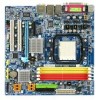
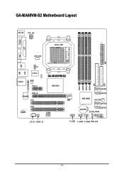
ATX GA-MA69VM-S2 Motherboard Layout MS / KB ATX_12V COMA Socket AM2 LPT VGA CPU_FAN USB USB LAN TV AUDIO IT8716 CI BIOS PCIE_4 GA-MA69VM-S2 AMD 690V F_AUDIO RTL8110SC PCIE_16 PCI1 PCI2 CODEC COMB CD_IN SPDIF_IO DDRII1 DDRII2 DDRII3 DDRII4 IDE SATAII2 SATAII0 AMD SB600 SYS_FAN SATAII3 BATTERY SATAII1 CLR_CMOS F_PANEL F_USB1 F_USB2 F_USB3 PWR_LED FDD - 7 -
ATX GA-MA69VM-S2 Motherboard Layout MS / KB ATX_12V COMA Socket AM2 LPT VGA CPU_FAN USB USB LAN TV AUDIO IT8716 CI BIOS PCIE_4 GA-MA69VM-S2 AMD 690V F_AUDIO RTL8110SC PCIE_16 PCI1 PCI2 CODEC COMB CD_IN SPDIF_IO DDRII1 DDRII2 DDRII3 DDRII4 IDE SATAII2 SATAII0 AMD SB600 SYS_FAN SATAII3 BATTERY SATAII1 CLR_CMOS F_PANEL F_USB1 F_USB2 F_USB3 PWR_LED FDD - 7 -
Manual
Page 10
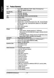
... 2.0/1.1 ports by cables Š 1 Power LED connector Š 1 COMB connector Š 1 Chassis Intrusion connector Š 1 TV out connector GA-MA69VM-S2 Motherboard - 10 - Supports RAID 0, RAID 1,and RAID 0+1for Serial ATA O.S Support Š Microsoft Windows 2000/XP/Vista Memory Š 4 ... connector Š 4 SATA 3Gb/s connectors Š 1 CPU fan connector Š 1 system fan connector Š 1 front panel connector Š 1 front audio connector Š 1 CD In connector Š 1 S/PDIF In/Out connector Š 3 USB 2.0/1.1 connectors for AMD AthlonTM 64 FX / AthlonTM 64 X2...
... 2.0/1.1 ports by cables Š 1 Power LED connector Š 1 COMB connector Š 1 Chassis Intrusion connector Š 1 TV out connector GA-MA69VM-S2 Motherboard - 10 - Supports RAID 0, RAID 1,and RAID 0+1for Serial ATA O.S Support Š Microsoft Windows 2000/XP/Vista Memory Š 4 ... connector Š 4 SATA 3Gb/s connectors Š 1 CPU fan connector Š 1 system fan connector Š 1 front panel connector Š 1 front audio connector Š 1 CD In connector Š 1 S/PDIF In/Out connector Š 3 USB 2.0/1.1 connectors for AMD AthlonTM 64 FX / AthlonTM 64 X2...

Manual
Page 11
... I/O Š 1 PS/2 keyboard port Š 1 PS/2 mouse port Š 1 parallel port Š 1 COMA port Š 1 VGA port Š 4 USB 2.0/1.1 ports Š 1 RJ-45 port Š 6 audio jacks (Line In / Line Out / MIC In/Surround Speaker Out (Rear Speaker Out)/Center/Subwoofer Speaker Out/Side Speaker Out) I/O Control Š IT8716 chip Hardware...
... I/O Š 1 PS/2 keyboard port Š 1 PS/2 mouse port Š 1 parallel port Š 1 COMA port Š 1 VGA port Š 4 USB 2.0/1.1 ports Š 1 RJ-45 port Š 6 audio jacks (Line In / Line Out / MIC In/Surround Speaker Out (Rear Speaker Out)/Center/Subwoofer Speaker Out/Side Speaker Out) I/O Control Š IT8716 chip Hardware...
Manual
Page 18
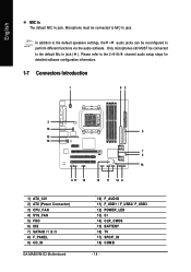
... addition to the default speakers settings, the ~ audio jacks can be reconfigured to the 2-/4-/6-/8- channel audio setup steps for detailed software configuration information. 1-7 Connectors Introduction 1 62 3 16 5 13 10 7 4 14 9 17 18 15 11 12 8 1) ATX_12V 2) ATX (Power Connector) 3) CPU_FAN 4) SYS_FAN 5) FDD 6) IDE 7) SATAII0 /1 /2 /3 8) F_PANEL 9) CD_IN GA-MA69VM-S2 Motherboard 10) F_AUDIO 11) F_USB1 / F_USB2...
... addition to the default speakers settings, the ~ audio jacks can be reconfigured to the 2-/4-/6-/8- channel audio setup steps for detailed software configuration information. 1-7 Connectors Introduction 1 62 3 16 5 13 10 7 4 14 9 17 18 15 11 12 8 1) ATX_12V 2) ATX (Power Connector) 3) CPU_FAN 4) SYS_FAN 5) FDD 6) IDE 7) SATAII0 /1 /2 /3 8) F_PANEL 9) CD_IN GA-MA69VM-S2 Motherboard 10) F_AUDIO 11) F_USB1 / F_USB2...
Manual
Page 22
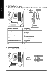
... On/Off Pin 1: LED anode(+) Pin 2: LED cathode(-) NC 9) CD_IN (CD In Connector) Connect CD-ROM or DVD-ROM audio out to the pin assignment below. Definition 1 CD-L 1 2 GND 3 GND 4 CD-R GA-MA69VM-S2 Motherboard - 22 - English 8) F_PANEL (Front Panel Jumper) Please connect the power LED, PC speaker, reset switch and power switch etc...
... On/Off Pin 1: LED anode(+) Pin 2: LED cathode(-) NC 9) CD_IN (CD In Connector) Connect CD-ROM or DVD-ROM audio out to the pin assignment below. Definition 1 CD-L 1 2 GND 3 GND 4 CD-R GA-MA69VM-S2 Motherboard - 22 - English 8) F_PANEL (Front Panel Jumper) Please connect the power LED, PC speaker, reset switch and power switch etc...

Manual
Page 23
... 1 2 3 4 5 6 7 8 9 10 Definition Power (5V) Power (5V) USB DXUSB DyUSB DX+ USB Dy+ GND GND No Pin NC - 23 - HD Audio: AC'97 Audio: 10 9 Pin No. Definition Pin No. Check the pin assignment carefully while you connect the front USB cable, incorrect connection between the module and...LINE2_R 5 Line Out (R) 6 FSENSE1 6 NC 7 FAUDIO_JD 7 NC 8 No Pin 8 No Pin 9 LINE2_L 9 Line Out (L) 10 FSENSE2 10 NC By default, the audio driver is configured to the instructions on Page 77 about the software settings. 11) F_ USB1 / F_USB2 / F_USB3 (Front USB Connector) Be careful with the...
... 1 2 3 4 5 6 7 8 9 10 Definition Power (5V) Power (5V) USB DXUSB DyUSB DX+ USB Dy+ GND GND No Pin NC - 23 - HD Audio: AC'97 Audio: 10 9 Pin No. Definition Pin No. Check the pin assignment carefully while you connect the front USB cable, incorrect connection between the module and...LINE2_R 5 Line Out (R) 6 FSENSE1 6 NC 7 FAUDIO_JD 7 NC 8 No Pin 8 No Pin 9 LINE2_L 9 Line Out (L) 10 FSENSE2 10 NC By default, the audio driver is configured to the instructions on Page 77 about the software settings. 11) F_ USB1 / F_USB2 / F_USB3 (Front USB Connector) Be careful with the...
Manual
Page 26
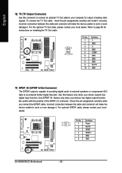
Refer to page 69 for output of analog video signals. Be careful with the polarity of providing digital audio to external speakers or compressed AC3 data to work or even damage it correctly. Incorrect connection between the cable and ...the optional TV Out cable, please contact your device has digital output function. Definition 5 1 6 2 1 Power 2 No Pin 3 SPDIF 4 SPDIFI 5 GND 6 GND GA-MA69VM-S2 Motherboard - 26 - Check the pin assignment carefully while you connect the S/PDIF cable, incorrect connection between the cable and connector will make the device unable...
Refer to page 69 for output of analog video signals. Be careful with the polarity of providing digital audio to external speakers or compressed AC3 data to work or even damage it correctly. Incorrect connection between the cable and ...the optional TV Out cable, please contact your device has digital output function. Definition 5 1 6 2 1 Power 2 No Pin 3 SPDIF 4 SPDIFI 5 GND 6 GND GA-MA69VM-S2 Motherboard - 26 - Check the pin assignment carefully while you connect the S/PDIF cable, incorrect connection between the cable and connector will make the device unable...
Manual
Page 36
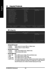
...to Native IDE mode.(Default value) RAID Set the SATA channel to AHCI mode. SATAJAHCI Set the SATA channel to RAID mode. GA-MA69VM-S2 Motherboard - 36 - OnChip SATA Controller Enabled Enable onboard SATA function. (Default value) Disabled Disable onboard SATA function. English 2-3 ... CMOS Setup Utility-Copyright (C) 1984-2007 Award Software Integrated Peripherals ` IDE Configuration OnChip SATA Controller OnChip SATA Type Onboard Audio Function Onboard LAN Function Onboard LAN Boot ROM OnChip USB Controller USB EHCI Controller USB Keyboard Support USB Mouse Support Legacy ...
...to Native IDE mode.(Default value) RAID Set the SATA channel to AHCI mode. SATAJAHCI Set the SATA channel to RAID mode. GA-MA69VM-S2 Motherboard - 36 - OnChip SATA Controller Enabled Enable onboard SATA function. (Default value) Disabled Disable onboard SATA function. English 2-3 ... CMOS Setup Utility-Copyright (C) 1984-2007 Award Software Integrated Peripherals ` IDE Configuration OnChip SATA Controller OnChip SATA Type Onboard Audio Function Onboard LAN Function Onboard LAN Boot ROM OnChip USB Controller USB EHCI Controller USB Keyboard Support USB Mouse Support Legacy ...

Manual
Page 37
... Auto Auto-detect onboard audio function. (Default value) Disabled Disable this function. Enabled Enable this function. Disabled Disable USB keyboard support. (Default value) USB Mouse Support Enabled Enable USB mouse ...
... Auto Auto-detect onboard audio function. (Default value) Disabled Disable this function. Enabled Enable this function. Disabled Disable USB keyboard support. (Default value) USB Mouse Support Enabled Enable USB mouse ...

Manual
Page 59
... (C) 1984-2007 Award Software Integrated Peripherals Item Help ` IDE Configuration [Press Enter] MIteenmu LHeevlepl` OnChip SATA Controller [Enabled] Menu Level` OnChip SATA Type [RAID] Onboard Audio Function [Auto] Onboard LAN Function [Enabld] Onboard LAN Boot ROM [Disabled] OnChip USB Controller [Enabled] USB EHCI Controller [Enabled] USB Keyboard Support [Enabled] USB Mouse...
... (C) 1984-2007 Award Software Integrated Peripherals Item Help ` IDE Configuration [Press Enter] MIteenmu LHeevlepl` OnChip SATA Controller [Enabled] Menu Level` OnChip SATA Type [RAID] Onboard Audio Function [Auto] Onboard LAN Function [Enabld] Onboard LAN Boot ROM [Disabled] OnChip USB Controller [Enabled] USB EHCI Controller [Enabled] USB Keyboard Support [Enabled] USB Mouse...

Manual
Page 73
... output is applied. Doubleclick the icon to work correctly. Appendix The jack retasking capability supported by the audio software provided. For example, if a rear speaker is able to handle multiple audio streams (in Windows XP) Center/Subwoofer Speaker Out Rear Speaker Out Side Speaker Out Line In Line Out... at the same time. Stereo Speakers Connection and Settings: We recommend that if you wish to connect a microphone, you can also find an Audio Manager icon in your system tray (you can , for instance, listen to MP3 music, have become a reality so you MUST connect it ...
... output is applied. Doubleclick the icon to work correctly. Appendix The jack retasking capability supported by the audio software provided. For example, if a rear speaker is able to handle multiple audio streams (in Windows XP) Center/Subwoofer Speaker Out Rear Speaker Out Side Speaker Out Line In Line Out... at the same time. Stereo Speakers Connection and Settings: We recommend that if you wish to connect a microphone, you can also find an Audio Manager icon in your system tray (you can , for instance, listen to MP3 music, have become a reality so you MUST connect it ...

Manual
Page 74
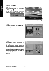
... and click OK. STEP 2: In the Audio Control Panel, click the Audio I /O tab. GA-M69VM-S2 Motherboard - 74 - English STEP 2: In the Audio Control Panel, click the Audio I /O tab. STEP 3: After a speaker or headphone is connected. In the upper left list, click 2CH Speaker. The 2-channel audio setup is completed. 4 Channel Audio Setup STEP 1 : After installation of the...
... and click OK. STEP 2: In the Audio Control Panel, click the Audio I /O tab. GA-M69VM-S2 Motherboard - 74 - English STEP 2: In the Audio Control Panel, click the Audio I /O tab. STEP 3: After a speaker or headphone is connected. In the upper left list, click 2CH Speaker. The 2-channel audio setup is completed. 4 Channel Audio Setup STEP 1 : After installation of the...

Manual
Page 75
...the icon in your system tray (you what type of equipment is completed. 6 Channel Audio Setup STEP 1 : After installation of the audio driver, you should find an Audio Manager icon in Control Panel). STEP 2: In the Audio Control Panel, click the Audio I/O tab. Choose a device depending on the type of speaker connected (4-channel... of Front Speaker Out (Line Out), Rear Speaker Out, and Center/Subwoofer Speaker Out) then click OK. The 6-channel audio setup is connected. In the upper left list, click 6CH Speaker. STEP 3: After plugging in 4-channel speakers to the rear speaker jacks, a ...
...the icon in your system tray (you what type of equipment is completed. 6 Channel Audio Setup STEP 1 : After installation of the audio driver, you should find an Audio Manager icon in Control Panel). STEP 2: In the Audio Control Panel, click the Audio I/O tab. Choose a device depending on the type of speaker connected (4-channel... of Front Speaker Out (Line Out), Rear Speaker Out, and Center/Subwoofer Speaker Out) then click OK. The 6-channel audio setup is connected. In the upper left list, click 6CH Speaker. STEP 3: After plugging in 4-channel speakers to the rear speaker jacks, a ...
Manual
Page 76
... depending on the type of speaker connected (8-channel audio consists of equipment is completed. STEP 2: In the Audio Control Panel, click the Audio I/O tab. STEP 3: After plugging in Control Panel). GA-M69VM-S2 Motherboard - 76 - English 8 Channel Audio Setup STEP 1 : After installation of the audio driver, you should find an Audio Manager icon in your system tray (you...
... depending on the type of speaker connected (8-channel audio consists of equipment is completed. STEP 2: In the Audio Control Panel, click the Audio I/O tab. STEP 3: After plugging in Control Panel). GA-M69VM-S2 Motherboard - 76 - English 8 Channel Audio Setup STEP 1 : After installation of the audio driver, you should find an Audio Manager icon in your system tray (you...

Manual
Page 77
Appendix This action completes the AC'97 Audio configuration. - 77 - AC'97 Audio Configuration: To enable the front panel audio connector to support AC97 Audio mode, go to the Audio Control Panel and click the Audio I/O tab. In the ANALOG area, click the Tool icon and then select the Disable front panel jack detection check box. English Sound Effect Configuration: At the Sound Effect menu, users can adjust sound option settings as desired.
Appendix This action completes the AC'97 Audio configuration. - 77 - AC'97 Audio Configuration: To enable the front panel audio connector to support AC97 Audio mode, go to the Audio Control Panel and click the Audio I/O tab. In the ANALOG area, click the Tool icon and then select the Disable front panel jack detection check box. English Sound Effect Configuration: At the Sound Effect menu, users can adjust sound option settings as desired.


