Manual
Page 4
Table of Contents Box Contents...6 Optional Items...6 GA-M68MT-S2P Motherboard Layout 7 GA-M68MT-S2P Motherboard Block Diagram 8 Chapter 1 Hardware Installation 9 1-1 Installation Precautions 9 1-2 Product Specifications 10 1-3 Installing the CPU and CPU Cooler 13 1-3-1 Installing the CPU 13 1-3-2 Installing the CPU Cooler 15 1-4 Installing the Memory 16 1-4-1 Dual Channel Memory Configuration 16 1-4-2 Installing a Memory 17 1-5 Installing an Expansion Card 18 1-6 Back Panel...
Table of Contents Box Contents...6 Optional Items...6 GA-M68MT-S2P Motherboard Layout 7 GA-M68MT-S2P Motherboard Block Diagram 8 Chapter 1 Hardware Installation 9 1-1 Installation Precautions 9 1-2 Product Specifications 10 1-3 Installing the CPU and CPU Cooler 13 1-3-1 Installing the CPU 13 1-3-2 Installing the CPU Cooler 15 1-4 Installing the Memory 16 1-4-1 Dual Channel Memory Configuration 16 1-4-2 Installing a Memory 17 1-5 Installing an Expansion Card 18 1-6 Back Panel...
Manual
Page 8
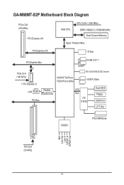
GA-M68MT-S2P Motherboard Block Diagram PCIe CLK (100 MHz) 1 PCI Express x16 AM3 CPU CPU CLK+/- (200 MHz) DDR3 1666(O.C.)/1066/800 MHz Dual Channel Memory Hyper Transport Bus PCI Express x16 1 D-Sub PCI Express Bus 8 USB 2.0/1.1 x1 PCIe CLK (100 MHz) 1 PCI Express x1 LAN RJ45 Realtek RTL8211CL PCI Bus NVIDIA® GeForce 7025/nForce 630a ATA-133/100/66/33 IDE Channel 4 SATA 3Gb/s LPC Bus iTE IT8720 Dual BIOS Floppy COM Port LPT Port CODEC PS/2 KB/Mouse MIC Line Out Line In S/PDIF In S/PDIF Out 2 PCI PCI CLK (33 MHz) - 8 -
GA-M68MT-S2P Motherboard Block Diagram PCIe CLK (100 MHz) 1 PCI Express x16 AM3 CPU CPU CLK+/- (200 MHz) DDR3 1666(O.C.)/1066/800 MHz Dual Channel Memory Hyper Transport Bus PCI Express x16 1 D-Sub PCI Express Bus 8 USB 2.0/1.1 x1 PCIe CLK (100 MHz) 1 PCI Express x1 LAN RJ45 Realtek RTL8211CL PCI Bus NVIDIA® GeForce 7025/nForce 630a ATA-133/100/66/33 IDE Channel 4 SATA 3Gb/s LPC Bus iTE IT8720 Dual BIOS Floppy COM Port LPT Port CODEC PS/2 KB/Mouse MIC Line Out Line In S/PDIF In S/PDIF Out 2 PCI PCI CLK (33 MHz) - 8 -

Manual
Page 9
...; Do not place the computer system in a high-temperature environment. • Turning on the computer power during the installation process can become damaged as a motherboard, CPU or memory. ponents such as a result of the product, please consult a certified computer technician. - 9 - Hardware Installation Prior to installation, carefully read the user's manual and...
...; Do not place the computer system in a high-temperature environment. • Turning on the computer power during the installation process can become damaged as a motherboard, CPU or memory. ponents such as a result of the product, please consult a certified computer technician. - 9 - Hardware Installation Prior to installation, carefully read the user's manual and...
Manual
Page 10
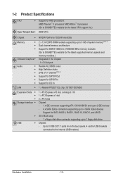
... Transport Bus Support for AM3 processors: AMD Phenom™ II processor/ AMD Athlon™ II processor (Go to GIGABYTE's website for the latest CPU support list.) 2000 MT/s Chipset NVIDIA® GeForce 7025/nForce 630a Memory Onboard Graphics &#...to 8 GB of system memory (Note 1) Dual channel memory architecture Support for DDR3 1666(O.C.)/1066/800 MHz memory modules (Go to GIGABYTE's website for the latest supported memory speeds and memory modules.) Integrated in the Chipset: - 1 x D-Sub port Realtek ALC888B ...
... Transport Bus Support for AM3 processors: AMD Phenom™ II processor/ AMD Athlon™ II processor (Go to GIGABYTE's website for the latest CPU support list.) 2000 MT/s Chipset NVIDIA® GeForce 7025/nForce 630a Memory Onboard Graphics &#...to 8 GB of system memory (Note 1) Dual channel memory architecture Support for DDR3 1666(O.C.)/1066/800 MHz memory modules (Go to GIGABYTE's website for the latest supported memory speeds and memory modules.) Integrated in the Chipset: - 1 x D-Sub port Realtek ALC888B ...
Manual
Page 11
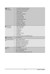
...ATX main power connector w 1 x 4-pin ATX 12V power connector w 1 x floppy disk drive connector w 1 x IDE connector w 4 x SATA 3Gb/s connectors w 1 x CPU fan header w 1 x system fan header w 1 x front panel header w 1 x front panel audio header w 1 x CD In connector w 1 x S/PDIF In/Out ... Monitor w w w w w w BIOS w w w w System voltage detection CPU/System temperature detection CPU/System fan speed detection CPU/System overheating warning CPU/System fan fail warning CPU fan speed control (Note 3) 2 x 8 Mbit flash Use of licensed AWARD BIOS...
...ATX main power connector w 1 x 4-pin ATX 12V power connector w 1 x floppy disk drive connector w 1 x IDE connector w 4 x SATA 3Gb/s connectors w 1 x CPU fan header w 1 x system fan header w 1 x front panel header w 1 x front panel audio header w 1 x CD In connector w 1 x S/PDIF In/Out ... Monitor w w w w w w BIOS w w w w System voltage detection CPU/System temperature detection CPU/System fan speed detection CPU/System overheating warning CPU/System fan fail warning CPU fan speed control (Note 3) 2 x 8 Mbit flash Use of licensed AWARD BIOS...

Manual
Page 12
..., you have to use an HD front panel audio module and enable the multi-channel audio feature through the audio driver. (Note 3) Whether the CPU fan speed control function is supported will depend on the CPU cooler you install. (Note 4) Available functions in EasyTune may differ by motherboard model. Hardware Installation - 12 -
..., you have to use an HD front panel audio module and enable the multi-channel audio feature through the audio driver. (Note 3) Whether the CPU fan speed control function is supported will depend on the CPU cooler you install. (Note 4) Available functions in EasyTune may differ by motherboard model. Hardware Installation - 12 -
Manual
Page 13
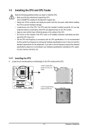
... both sides of the CPU and alignment keys on the CPU socket.) • Apply an even and thin layer of thermal grease on the surface of the CPU. • Do not turn on the computer if the CPU cooler is not recommended that the motherboard supports the CPU. (Go to GIGABYTE's website for the latest... CPU support list.) • Always turn off the computer and unplug the power ...
... both sides of the CPU and alignment keys on the CPU socket.) • Apply an even and thin layer of thermal grease on the surface of the CPU. • Do not turn on the computer if the CPU cooler is not recommended that the motherboard supports the CPU. (Go to GIGABYTE's website for the latest... CPU support list.) • Always turn off the computer and unplug the power ...

Manual
Page 14
...1: Completely lift up the CPU socket locking lever. Make sure that the CPU pins fit perfectly into the CPU socket. The CPU cannot fit in if oriented incorrectly. Follow the steps below to correctly install the CPU into the motherboard CPU socket. • Before installing the CPU, make sure to turn off... the computer and unplug the power cord from the power outlet to prevent damage to the CPU. • Do not force the CPU into their holes. Hardware Installation - 14 - Once the CPU is positioned into its socket, place one (small triangle marking) with the triangle mark on...
...1: Completely lift up the CPU socket locking lever. Make sure that the CPU pins fit perfectly into the CPU socket. The CPU cannot fit in if oriented incorrectly. Follow the steps below to correctly install the CPU into the motherboard CPU socket. • Before installing the CPU, make sure to turn off... the computer and unplug the power cord from the power outlet to prevent damage to the CPU. • Do not force the CPU into their holes. Hardware Installation - 14 - Once the CPU is positioned into its socket, place one (small triangle marking) with the triangle mark on...

Manual
Page 15
... Follow the steps below to correctly install the CPU cooler on the CPU. (The following procedure uses the GIGABYTE cooler as the picture above shows) to lock into place. (Refer to the CPU. Step 4: Turn the cam handle from the left side to the right side (as the example.) Step 1: Apply an even and... thin layer of thermal grease on the surface of the CPU cooler to the...
... Follow the steps below to correctly install the CPU cooler on the CPU. (The following procedure uses the GIGABYTE cooler as the picture above shows) to lock into place. (Refer to the CPU. Step 4: Turn the cam handle from the left side to the right side (as the example.) Step 1: Apply an even and... thin layer of thermal grease on the surface of the CPU cooler to the...

Manual
Page 16
...guidelines before installing the memory in only one DDR3 memory module is installed. 2. A memory module can be used . (Go to GIGABYTE's website for the latest supported memory speeds and memory modules.) • Always turn off the computer and unplug the power cord from the power...are divided into two channels and each channel has two memory sockets as following: Channel 0: DDR3_1 Channel 1: DDR3_2 DDR3_1 DDR3_2 Due to CPU limitation, read the following guidelines before installing the memory to insert the memory, switch the direction. 1-4-1 Dual Channel Memory Configuration This ...
...guidelines before installing the memory in only one DDR3 memory module is installed. 2. A memory module can be used . (Go to GIGABYTE's website for the latest supported memory speeds and memory modules.) • Always turn off the computer and unplug the power cord from the power...are divided into two channels and each channel has two memory sockets as following: Channel 0: DDR3_1 Channel 1: DDR3_2 DDR3_1 DDR3_2 Due to CPU limitation, read the following guidelines before installing the memory to insert the memory, switch the direction. 1-4-1 Dual Channel Memory Configuration This ...
Manual
Page 22
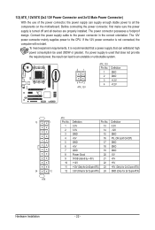
... connector in the correct orientation. If a power supply is turned off and all the components on the motherboard. Connect the power supply cable to the CPU. 1/2) ATX_12V/ATX (2x2 12V Power Connector and 2x12 Main Power Connector) With the use of the power connector, the power supply can lead to an...
... connector in the correct orientation. If a power supply is turned off and all the components on the motherboard. Connect the power supply cable to the CPU. 1/2) ATX_12V/ATX (2x2 12V Power Connector and 2x12 Main Power Connector) With the use of the power connector, the power supply can lead to an...

Manual
Page 23
...be installed inside the chassis. 1 CPU_FAN 1 SYS_FAN CPU_FAN: Pin No. Hardware Installation For optimum heat dissipation, it in damage to prevent your CPU and system from overheating. Overheating may result in the correct orientation (the black connector wire is typically designated by a stripe of the connector ... Sense 4 Speed Control SYS_FAN: Pin No. 1 2 3 Definition GND +12V Sense • Be sure to connect fan cables to the fan headers to the CPU or the system may hang. • These fan headers are : 360 KB, 720 KB, 1.2 MB, 1.44 MB, and 2.88 MB. For purchasing the...
...be installed inside the chassis. 1 CPU_FAN 1 SYS_FAN CPU_FAN: Pin No. Hardware Installation For optimum heat dissipation, it in damage to prevent your CPU and system from overheating. Overheating may result in the correct orientation (the black connector wire is typically designated by a stripe of the connector ... Sense 4 Speed Control SYS_FAN: Pin No. 1 2 3 Definition GND +12V Sense • Be sure to connect fan cables to the fan headers to the CPU or the system may hang. • These fan headers are : 360 KB, 720 KB, 1.2 MB, 1.44 MB, and 2.88 MB. For purchasing the...

Manual
Page 31
... Fail-Safe Defaults Load Optimized Defaults Set Supervisor Password Set User Password Save & Exit Setup Exit Without Saving Select Item F10: Save & Exit Setup Change CPU's Clock & Voltage BIOS Setup Program Function Keys Move the selection bar to select an item Execute command or enter the submenu Main Menu: Exit the...
... Fail-Safe Defaults Load Optimized Defaults Set Supervisor Password Set User Password Save & Exit Setup Exit Without Saving Select Item F10: Save & Exit Setup Change CPU's Clock & Voltage BIOS Setup Program Function Keys Move the selection bar to select an item Execute command or enter the submenu Main Menu: Exit the...
Manual
Page 32
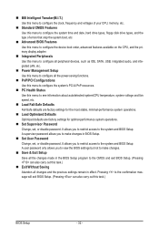
...also carry out this task.) BIOS Setup - 32 - A user password only allows you to restrict access to see information about autodetected system/CPU temperature, system voltage and fan speed, etc. Load Fail-Safe Defaults Fail-Safe defaults are factory settings for the most stable,...Password Change, set , or disable password. MB Intelligent Tweaker(M.I.T.) Use this menu to configure the clock, frequency and voltages of your CPU, memory, etc. Standard CMOS Features Use this menu to configure the system time and date, hard drive types, floppy disk drive ...
...also carry out this task.) BIOS Setup - 32 - A user password only allows you to restrict access to see information about autodetected system/CPU temperature, system voltage and fan speed, etc. Load Fail-Safe Defaults Fail-Safe defaults are factory settings for the most stable,...Password Change, set , or disable password. MB Intelligent Tweaker(M.I.T.) Use this menu to configure the clock, frequency and voltages of your CPU, memory, etc. Standard CMOS Features Use this menu to configure the system time and date, hard drive types, floppy disk drive ...

Manual
Page 33
... If this occurs, clear the CMOS values and reset the board to default values.) Set Memory Clock Determines whether to CPU, chipset, or memory and reduce the useful life of these components. Incorrectly doing overclock may result in damage to manually...CMOS Setup Utility-Copyright (C) 1984-2009 Award Software MB Intelligent Tweaker(M.I.T.) Set Memory Clock x Memory Clock } DRAM Configuration CPU NB VID Control CPU Voltage Control DDR3 Voltage Control Normal CPU Vcore [Auto] x5.33 1066Mhz [Press Enter] [Normal] [Normal] [Auto] 1.3500V Item Help Menu Level &#...
... If this occurs, clear the CMOS values and reset the board to default values.) Set Memory Clock Determines whether to CPU, chipset, or memory and reduce the useful life of these components. Incorrectly doing overclock may result in damage to manually...CMOS Setup Utility-Copyright (C) 1984-2009 Award Software MB Intelligent Tweaker(M.I.T.) Set Memory Clock x Memory Clock } DRAM Configuration CPU NB VID Control CPU Voltage Control DDR3 Voltage Control Normal CPU Vcore [Auto] x5.33 1066Mhz [Press Enter] [Normal] [Normal] [Auto] 1.3500V Item Help Menu Level &#...

Manual
Page 35
...Default: Disabled) CKE Power Down Control Allows you to set the CPU voltage. Auto sets the CPU voltage as required. Note: Increasing memory voltage may result in damage to set the CPU Northbridge VID voltage. CPU Voltage Control Allows you to your CPU. - 35 - CPU NB VID Control Allows you to select a CKE power down ... may result in damage to RAS Delay Options are : Auto (default), 4T~7T. CKE Power Down Mode Determines whether to your CPU or reduce the useful life of the memory. The adjustable range is from +0.05V to power down mode. BIOS Setup DDR3 Voltage Control ...
...Default: Disabled) CKE Power Down Control Allows you to set the CPU voltage. Auto sets the CPU voltage as required. Note: Increasing memory voltage may result in damage to set the CPU Northbridge VID voltage. CPU Voltage Control Allows you to your CPU. - 35 - CPU NB VID Control Allows you to select a CKE power down ... may result in damage to RAS Delay Options are : Auto (default), 4T~7T. CKE Power Down Mode Determines whether to your CPU or reduce the useful life of the memory. The adjustable range is from +0.05V to power down mode. BIOS Setup DDR3 Voltage Control ...
Manual
Page 38
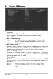
... computer system can function as multiple virtual systems. (Default: Enabled) AMD K8 Cool&Quiet control Auto Lets the AMD Cool'n'Quiet driver dynamically adjust the CPU clock and VID to reduce heat output from your computer and its power consumption. (Default) Disabled Disables this item, set the password(s) under the Set...
... computer system can function as multiple virtual systems. (Default: Enabled) AMD K8 Cool&Quiet control Auto Lets the AMD Cool'n'Quiet driver dynamically adjust the CPU clock and VID to reduce heat output from your computer and its power consumption. (Default) Disabled Disables this item, set the password(s) under the Set...

Manual
Page 46
... Vcore DDR3 1.5V +3.3V +12V Current System Temperature Current CPU Temperature Current CPU FAN Speed Current SYSTEM FAN Speed System Warning Temperature CPU Warning Temperature CPU FAN Fail Warning SYSTEM FAN Fail Warning CPU Smart FAN Control CPU Smart FAN Mode [Disabled] No 1.364V 1.520V 3.280V ... record of the chassis intrusion detection device attached to the motherboard CI header. If disabled, the CPU fan runs at next boot. (Default: Disabled) Case Opened Displays the detection status of previous chassis intrusion status. Enabled allows...
... Vcore DDR3 1.5V +3.3V +12V Current System Temperature Current CPU Temperature Current CPU FAN Speed Current SYSTEM FAN Speed System Warning Temperature CPU Warning Temperature CPU FAN Fail Warning SYSTEM FAN Fail Warning CPU Smart FAN Control CPU Smart FAN Mode [Disabled] No 1.364V 1.520V 3.280V ... record of the chassis intrusion detection device attached to the motherboard CI header. If disabled, the CPU fan runs at next boot. (Default: Disabled) Case Opened Displays the detection status of previous chassis intrusion status. Enabled allows...

Manual
Page 47
PWM Sets PWM mode for a 3-pin CPU fan. Auto Lets the BIOS automatically detect the type of CPU fan installed and sets the optimal CPU fan control mode. (Default) Voltage Sets Voltage mode for a 4-pin CPU fan. - 47 - This item is configurable only if CPU Smart FAN Control is set to control CPU fan speed. BIOS Setup CPU Smart FAN Mode Specifies how to Enabled.
PWM Sets PWM mode for a 3-pin CPU fan. Auto Lets the BIOS automatically detect the type of CPU fan installed and sets the optimal CPU fan control mode. (Default) Voltage Sets Voltage mode for a 4-pin CPU fan. - 47 - This item is configurable only if CPU Smart FAN Control is set to control CPU fan speed. BIOS Setup CPU Smart FAN Mode Specifies how to Enabled.

Manual
Page 62
.... Available functions in EasyTune 6 may result in Easy mode/Advanced mode, be changed linearly based on the installed memory module(s). 4-3 EasyTune 6 GIGABYTE's EasyTune 6 is a simple and easy-to-use your ATI or NVIDIA graphics card. You can choose the alert sound from a profile.... and fan speed and set . Before you to default values. The user-friendly EasyTune 6 interface also includes tabbed pages for CPU and memory information, letting users read their system settings or do overclock/overvoltage in the notification area. Grayed-out area(s) indicates that...
.... Available functions in EasyTune 6 may result in Easy mode/Advanced mode, be changed linearly based on the installed memory module(s). 4-3 EasyTune 6 GIGABYTE's EasyTune 6 is a simple and easy-to-use your ATI or NVIDIA graphics card. You can choose the alert sound from a profile.... and fan speed and set . Before you to default values. The user-friendly EasyTune 6 interface also includes tabbed pages for CPU and memory information, letting users read their system settings or do overclock/overvoltage in the notification area. Grayed-out area(s) indicates that...


