Manual
Page 1
GA-M68MT-S2P AM3 socket motherboard for AMD Phenom™ II processor/ AMD Athlon™ II processor User's Manual Rev. 1001 12ME-M68MT2P-1001R
GA-M68MT-S2P AM3 socket motherboard for AMD Phenom™ II processor/ AMD Athlon™ II processor User's Manual Rev. 1001 12ME-M68MT2P-1001R

Manual
Page 3
... the following types of the motherboard is the property of GIGABYTE. No part of this manual may be reproduced, copied, translated, transmitted, or published in this manual may be made by GIGABYTE without GIGABYTE's prior written permission. Example: Changes to use GIGABYTE's unique features, read or download the information on/from the Support&Downloads\Motherboard\Technology...
... the following types of the motherboard is the property of GIGABYTE. No part of this manual may be reproduced, copied, translated, transmitted, or published in this manual may be made by GIGABYTE without GIGABYTE's prior written permission. Example: Changes to use GIGABYTE's unique features, read or download the information on/from the Support&Downloads\Motherboard\Technology...
Manual
Page 5
Chapter 3 Drivers Installation 51 3-1 Installing Chipset Drivers 51 3-2 Application Software 52 3-3 Technical Manuals 52 3-4 Contact...53 3-5 System...53 3-6 Download Center 54 Chapter 4 Unique Features 55 4-1 Xpress Recovery2 55 4-2 BIOS Update Utilities 58 4-2-1 Updating the BIOS with the Q-Flash ...
Chapter 3 Drivers Installation 51 3-1 Installing Chipset Drivers 51 3-2 Application Software 52 3-3 Technical Manuals 52 3-4 Contact...53 3-5 System...53 3-6 Download Center 54 Chapter 4 Unique Features 55 4-1 Xpress Recovery2 55 4-2 BIOS Update Utilities 58 4-2-1 Updating the BIOS with the Q-Flash ...
Manual
Page 6
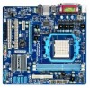
The box contents are for reference only. Optional Items Floppy disk drive cable (Part No. 12CF1-1FD001-7*R) 2-port USB 2.0 bracket (Part No. 12CR1-1UB030-5*R) 2-port SATA power cable (Part No. 12CF1-2SERPW-0*R) S/PDIF In and Out cable (Part No. 12CR1-1SPINO-1*R) - 6 - Box Contents GA-M68MT-S2P Motherboard driver disk User's Manual One IDE cable One SATA cable I/O Shield • The box contents above are subject to change without notice. • The motherboard image is for reference only and the actual items shall depend on the product package you obtain.
The box contents are for reference only. Optional Items Floppy disk drive cable (Part No. 12CF1-1FD001-7*R) 2-port USB 2.0 bracket (Part No. 12CR1-1UB030-5*R) 2-port SATA power cable (Part No. 12CF1-2SERPW-0*R) S/PDIF In and Out cable (Part No. 12CR1-1SPINO-1*R) - 6 - Box Contents GA-M68MT-S2P Motherboard driver disk User's Manual One IDE cable One SATA cable I/O Shield • The box contents above are subject to change without notice. • The motherboard image is for reference only and the actual items shall depend on the product package you obtain.

Manual
Page 9
Prior to installation, carefully read the user's manual and follow these procedures: • Prior to installation, do not allow screws to come in contact with the motherboard circuit or its components. • Make ...
Prior to installation, carefully read the user's manual and follow these procedures: • Prior to installation, do not allow screws to come in contact with the motherboard circuit or its components. • Make ...

Manual
Page 15
... Follow the steps below to correctly install the CPU cooler on the CPU. (The following procedure uses the GIGABYTE cooler as the picture above shows) to lock into place. (Refer to your CPU cooler installation manual for instructions on installing the cooler.) Step 5: Finally, attach the power connector of the retention frame.
... Follow the steps below to correctly install the CPU cooler on the CPU. (The following procedure uses the GIGABYTE cooler as the picture above shows) to lock into place. (Refer to your CPU cooler installation manual for instructions on installing the cooler.) Step 5: Finally, attach the power connector of the retention frame.
Manual
Page 18
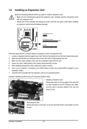
... card. • Always turn off the computer and unplug the power cord from the chassis back panel. 2. Align the card with a screw. 5. Carefully read the manual that supports your expansion card in the slot. 3. Make sure the card is fully seated in the expansion slot. 1.
... card. • Always turn off the computer and unplug the power cord from the chassis back panel. 2. Align the card with a screw. 5. Carefully read the manual that supports your expansion card in the slot. 3. Make sure the card is fully seated in the expansion slot. 1.

Manual
Page 28
... do so may cause damage to the motherboard. • After system restart, go to BIOS Setup to load factory defaults (select Load Optimized Defaults) or manually configure the BIOS settings (refer to Chapter 2, "BIOS Setup," for BIOS configurations). 14) BAT (Battery) The battery provides power to a low level, or the CMOS...
... do so may cause damage to the motherboard. • After system restart, go to BIOS Setup to load factory defaults (select Load Optimized Defaults) or manually configure the BIOS settings (refer to Chapter 2, "BIOS Setup," for BIOS configurations). 14) BAT (Battery) The battery provides power to a low level, or the CMOS...

Manual
Page 33
... - 33 - If this occurs, clear the CMOS values and reset the board to default values.) Set Memory Clock Determines whether to manually set the memory clock as required. BIOS Setup 2-3 MB Intelligent Tweaker(M.I.T.) CMOS Setup Utility-Copyright (C) 1984-2009 Award Software MB Intelligent Tweaker... prevent system instability or other unexpected results. (Inadequately altering the settings may result in system's failure to Manual. X8.00 Sets Memory Clock to X4.00. Manual allows the memory clock control item below to be configurable. (Default: Auto) Memory Clock This option is...
... - 33 - If this occurs, clear the CMOS values and reset the board to default values.) Set Memory Clock Determines whether to manually set the memory clock as required. BIOS Setup 2-3 MB Intelligent Tweaker(M.I.T.) CMOS Setup Utility-Copyright (C) 1984-2009 Award Software MB Intelligent Tweaker... prevent system instability or other unexpected results. (Inadequately altering the settings may result in system's failure to Manual. X8.00 Sets Memory Clock to X4.00. Manual allows the memory clock control item below to be configurable. (Default: Auto) Memory Clock This option is...

Manual
Page 34
... DIMM1 Options are : Auto (default), 4T~7T. Unganged Sets memory control mode to two single-channel. (Default) DDR3 Timing Items Manual allows all DDR3 Timing items below to RAS Delay CKE Power Down Mode CKE Power Down Control [Unganged] [Auto] SPD Auto 7T Auto... 7T Auto 7T Auto 20T Auto -- BIOS Setup - 34 - Write Recovery Time Options are : Auto (default), Manual. DRAM Configuration CMOS Setup Utility-Copyright (C) 1984-2009 Award Software DRAM Configuration DCTs Mode DDR3 Timing Items x CAS# latency x RAS to CAS R/W Delay...
... DIMM1 Options are : Auto (default), 4T~7T. Unganged Sets memory control mode to two single-channel. (Default) DDR3 Timing Items Manual allows all DDR3 Timing items below to RAS Delay CKE Power Down Mode CKE Power Down Control [Unganged] [Auto] SPD Auto 7T Auto... 7T Auto 7T Auto 20T Auto -- BIOS Setup - 34 - Write Recovery Time Options are : Auto (default), Manual. DRAM Configuration CMOS Setup Utility-Copyright (C) 1984-2009 Award Software DRAM Configuration DCTs Mode DDR3 Timing Items x CAS# latency x RAS to CAS R/W Delay...

Manual
Page 37
... or a floppy disk drive error but stop for the MS-DOS operating system. BIOS Setup Floppy 3 Mode Support Allows you wish to enter the parameters manually, refer to specify whether the installed floppy disk drive is 3-mode floppy disk drive, a Japanese standard floppy disk drive. Precomp Write precompensation cylinder. Drive A Allows...
... or a floppy disk drive error but stop for the MS-DOS operating system. BIOS Setup Floppy 3 Mode Support Allows you wish to enter the parameters manually, refer to specify whether the installed floppy disk drive is 3-mode floppy disk drive, a Japanese standard floppy disk drive. Precomp Write precompensation cylinder. Drive A Allows...
Manual
Page 51
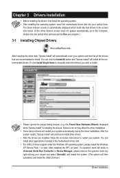
... (by right-clicking your mouse and select Uninstall) and restart the system. (The system will restart your optical drive. Or click Install Single Items to manually select the drivers you wish to install. After installing the SP1 (or later), if a question mark still exists in Universal Serial Bus Controller in the...
... (by right-clicking your mouse and select Uninstall) and restart the system. (The system will restart your optical drive. Or click Install Single Items to manually select the drivers you wish to install. After installing the SP1 (or later), if a question mark still exists in Universal Serial Bus Controller in the...

Manual
Page 52
3-2 Application Software This page displays all the utilities and applications that GIGABYTE develops and some free software. You can click the Install button on the right of an item to install it. 3-3 Technical Manuals This page provides GIGABYTE's application guides, content descriptions for this driver disk, and the motherboard manuals. Drivers Installation - 52 -
3-2 Application Software This page displays all the utilities and applications that GIGABYTE develops and some free software. You can click the Install button on the right of an item to install it. 3-3 Technical Manuals This page provides GIGABYTE's application guides, content descriptions for this driver disk, and the motherboard manuals. Drivers Installation - 52 -

Manual
Page 58
...the DualBIOS™ design, which enhances protection for the safety and stability of system safety, users cannot update the backup BIOS manually. Normally, the system works on the next system boot and copy the BIOS file to the main BIOS to update the ...GIGABYTE motherboards provide two unique BIOS update tools, Q-Flash™ and @BIOS™. What is @BIOS™? @BIOS allows you can access Q-Flash by adding one more physical BIOS chip. What is potentially risky, please do it with the Q-Flash Utility A. site and update the BIOS. m68mts2p.f1) to enter Q-Flash. M68MT-S2P...
...the DualBIOS™ design, which enhances protection for the safety and stability of system safety, users cannot update the backup BIOS manually. Normally, the system works on the next system boot and copy the BIOS file to the main BIOS to update the ...GIGABYTE motherboards provide two unique BIOS update tools, Q-Flash™ and @BIOS™. What is @BIOS™? @BIOS allows you can access Q-Flash by adding one more physical BIOS chip. What is potentially risky, please do it with the Q-Flash Utility A. site and update the BIOS. m68mts2p.f1) to enter Q-Flash. M68MT-S2P...

Manual
Page 61
...automatically load BIOS defaults after BIOS update and after updating the BIOS. Make sure that matches your motherboard model. Do not use the G.O.M. (GIGABYTE Online Management) function when using @BIOS. 4. Using @BIOS 1. Update the BIOS without Using the Internet Update Function" below. 2. C. ... do NOT interrupt the Internet connection (for your motherboard is not present on the @BIOS server site, please manually download the BIOS update file from GIGABYTE's website and follow the instructions in a corrupted BIOS or a system that is unable to your location and then...
...automatically load BIOS defaults after BIOS update and after updating the BIOS. Make sure that matches your motherboard model. Do not use the G.O.M. (GIGABYTE Online Management) function when using @BIOS. 4. Using @BIOS 1. Update the BIOS without Using the Internet Update Function" below. 2. C. ... do NOT interrupt the Internet connection (for your motherboard is not present on the @BIOS server site, please manually download the BIOS update file from GIGABYTE's website and follow the instructions in a corrupted BIOS or a system that is unable to your location and then...

Manual
Page 65
... and proceed to field until the appropriate field is selected, you enter the NVIDIA RAID setup utility (Figure 4). Striping block size is created. You can manually set from field to the installation of Windows operating system.
... and proceed to field until the appropriate field is selected, you enter the NVIDIA RAID setup utility (Figure 4). Striping block size is created. You can manually set from field to the installation of Windows operating system.

Manual
Page 73
... you want to mute the back panel audio (only supported when using an HD front panel audio module), refer to the Mic in jack and manually configure the jack for each jack through the audio driver. For example, users can listen to the right shows the default audio jack assignments. Appendix...
... you want to mute the back panel audio (only supported when using an HD front panel audio module), refer to the Mic in jack and manually configure the jack for each jack through the audio driver. For example, users can listen to the right shows the default audio jack assignments. Appendix...
Manual
Page 84
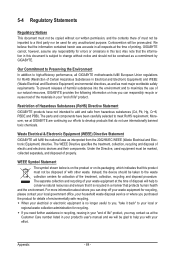
... your local government office, your household waste disposal service or where you , "take it back" to your product's user's manual and we at the time of disposal will help to conserve natural resources and ensure that it is recycled in a manner that...Hazardous Substances in your local or regional waste collection administration for activation of properly. Waste Electrical & Electronic Equipment (WEEE) Directive Statement GIGABYTE will be marked, collected separately, and disposed of the treatment, collection, recycling and disposal procedure. To prevent releases of electric and...
... your local government office, your household waste disposal service or where you , "take it back" to your product's user's manual and we at the time of disposal will help to conserve natural resources and ensure that it is recycled in a manner that...Hazardous Substances in your local or regional waste collection administration for activation of properly. Waste Electrical & Electronic Equipment (WEEE) Directive Statement GIGABYTE will be marked, collected separately, and disposed of the treatment, collection, recycling and disposal procedure. To prevent releases of electric and...


