Manual
Page 4
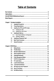
......6 GA-M61PME-S2 Motherboard Layout 7 Block Diagram...8 Chapter 1 Hardware Installation 9 1-1 Installation Precautions 9 1-2 Product Specifications 10 1-3 Installing the CPU and CPU Cooler 12 1-3-1 Installing the CPU 12 1-3-2 Installing the CPU Cooler 14 1-4 Installing the Memory 15 1-4-1 Dual Channel Memory Configuration 15 1-4-2 Installing a Memory 16 1-5 Installing an Expansion Card 17 1-6 Back Panel Connectors 18 1-7 Internal Connectors 20 Chapter 2 BIOS Setup 29 2-1 Startup Screen 30 2-2 The Main Menu 31 2-3 Standard CMOS Features 33 2-4 Advanced BIOS Features...
......6 GA-M61PME-S2 Motherboard Layout 7 Block Diagram...8 Chapter 1 Hardware Installation 9 1-1 Installation Precautions 9 1-2 Product Specifications 10 1-3 Installing the CPU and CPU Cooler 12 1-3-1 Installing the CPU 12 1-3-2 Installing the CPU Cooler 14 1-4 Installing the Memory 15 1-4-1 Dual Channel Memory Configuration 15 1-4-2 Installing a Memory 16 1-5 Installing an Expansion Card 17 1-6 Back Panel Connectors 18 1-7 Internal Connectors 20 Chapter 2 BIOS Setup 29 2-1 Startup Screen 30 2-2 The Main Menu 31 2-3 Standard CMOS Features 33 2-4 Advanced BIOS Features...

Manual
Page 5
...Updating the BIOS with the Q-Flash Utility 58 4-2-2 Updating the BIOS with the @BIOS Utility 61 4-3 EasyTune 5 ...63 4-4 Windows Vista ReadyBoost 64 Chapter 5 Appendix ...65 5-1 Configuring SATA Hard Drive(s 65 5-1-1 Configuring the Onboard SATA Controller 65 5-1-2 Making a SATA RAID Driver Diskette (For Windows XP and 2000 70 5-1-3 Installing the SATA RAID Driver and Operating System 71 5-2 Configuring Audio Input and Output 74 5-2-1 Configuring 2/4/5.1-Channel Audio 74 5-2-2 Installing the S/PDIFOut Cable (Optional 77 5-2-3 Configuring Microphone Recording 79 5-2-4 Using the Sound...
...Updating the BIOS with the Q-Flash Utility 58 4-2-2 Updating the BIOS with the @BIOS Utility 61 4-3 EasyTune 5 ...63 4-4 Windows Vista ReadyBoost 64 Chapter 5 Appendix ...65 5-1 Configuring SATA Hard Drive(s 65 5-1-1 Configuring the Onboard SATA Controller 65 5-1-2 Making a SATA RAID Driver Diskette (For Windows XP and 2000 70 5-1-3 Installing the SATA RAID Driver and Operating System 71 5-2 Configuring Audio Input and Output 74 5-2-1 Configuring 2/4/5.1-Channel Audio 74 5-2-2 Installing the S/PDIFOut Cable (Optional 77 5-2-3 Configuring Microphone Recording 79 5-2-4 Using the Sound...
Manual
Page 10
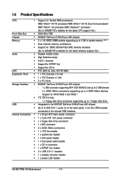
... connector supporting up to the internal USB headers) Internal Connectors 1 x 24-pin ATX main power connector 1 x 4-pin ATX 12V power connector 1 x floppy disk drive connector 1 x IDE connector 2 x SATA 3Gb/s connectors 1 x CPU fan header 1 x system fan header 1 x front panel header 1 x front panel audio header 1 x CD In connector 1 x S/PDIF Out header 2 x USB 2.0/1.1 headers 1 x chassis intrusion header 1 x power LED header GA-M61PME-S2 Motherboard...
... connector supporting up to the internal USB headers) Internal Connectors 1 x 24-pin ATX main power connector 1 x 4-pin ATX 12V power connector 1 x floppy disk drive connector 1 x IDE connector 2 x SATA 3Gb/s connectors 1 x CPU fan header 1 x system fan header 1 x front panel header 1 x front panel audio header 1 x CD In connector 1 x S/PDIF Out header 2 x USB 2.0/1.1 headers 1 x chassis intrusion header 1 x power LED header GA-M61PME-S2 Motherboard...

Manual
Page 17
..., go to BIOS Setup to the chassis back panel with the slot, and press down on the card are completely inserted into the PCI Express x16 slot. Secure the card's metal bracket to make any required BIOS changes for your computer. After installing all expansion cards, replace the chassis cover(s). 6. Turn on the slot and then lift the card straight out from the chassis back panel. 2. Example: Installing and Removing a PCI Express x16 Graphics Card: • Installing a Graphics Card: Gently...
..., go to BIOS Setup to the chassis back panel with the slot, and press down on the card are completely inserted into the PCI Express x16 slot. Secure the card's metal bracket to make any required BIOS changes for your computer. After installing all expansion cards, replace the chassis cover(s). 6. Turn on the slot and then lift the card straight out from the chassis back panel. 2. Example: Installing and Removing a PCI Express x16 Graphics Card: • Installing a Graphics Card: Gently...
Manual
Page 22
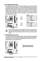
... GA-M61PME-S2 Motherboard - 22 - Overheating may result in the correct orientation. Definition 1 GND 1 CPU_FAN 2 +12V 3 Sense 4 Speed Control 1 SYS_FAN SYS_FAN: Pin No. 1 2 3 Definition GND +12V Sense • Be sure to connect fan cables to the fan headers to locate pin 1 of floppy disk drives supported are not configuration jumper blocks. Before connecting a floppy disk drive, be installed inside the chassis. Each fan header supplies a +12V power voltage and possesses a foolproof insertion design. When connecting a fan cable, be sure to connect it is used...
... GA-M61PME-S2 Motherboard - 22 - Overheating may result in the correct orientation. Definition 1 GND 1 CPU_FAN 2 +12V 3 Sense 4 Speed Control 1 SYS_FAN SYS_FAN: Pin No. 1 2 3 Definition GND +12V Sense • Be sure to connect fan cables to the fan headers to locate pin 1 of floppy disk drives supported are not configuration jumper blocks. Before connecting a floppy disk drive, be installed inside the chassis. Each fan header supplies a +12V power voltage and possesses a foolproof insertion design. When connecting a fan cable, be sure to connect it is used...
Manual
Page 24
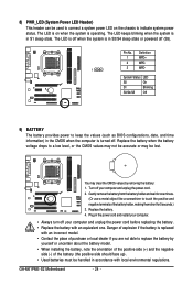
... the chassis to touch the positive and negative terminals of explosion if the battery is operating. Pin No. Replace the battery. 4. Danger of the battery holder, making them short for 5 seconds.) 3. Definition 1 MPD+ 2 MPD- 1 3 MPD- GA-M61PME-S2 Motherboard - 24 - The LED is in the power cord and restart your computer. • Always turn off . 8) PWR_LED (System Power LED Header) This header can be lost. Plug in S1 sleep state...
... the chassis to touch the positive and negative terminals of explosion if the battery is operating. Pin No. Replace the battery. 4. Danger of the battery holder, making them short for 5 seconds.) 3. Definition 1 MPD+ 2 MPD- 1 3 MPD- GA-M61PME-S2 Motherboard - 24 - The LED is in the power cord and restart your computer. • Always turn off . 8) PWR_LED (System Power LED Header) This header can be lost. Plug in S1 sleep state...

Manual
Page 26
... optical drive to activate AC'97 functioninality via the audio software in Chapter 5, "Configuring 2/4/5.1-Channel Audio." • Audio signals will make the device unable to Chapter 5, "Configuring 2/4/5.1/7.1-Channel Audio." • Some chassis provide a front panel audio module that came with your chassis front panel audio module to this header. Make sure the wire assignments of the module connector match the pin assignments of the front and back panel audio connections simultaneously. For HD Front Panel Audio...
... optical drive to activate AC'97 functioninality via the audio software in Chapter 5, "Configuring 2/4/5.1-Channel Audio." • Audio signals will make the device unable to Chapter 5, "Configuring 2/4/5.1/7.1-Channel Audio." • Some chassis provide a front panel audio module that came with your chassis front panel audio module to this header. Make sure the wire assignments of the module connector match the pin assignments of the front and back panel audio connections simultaneously. For HD Front Panel Audio...
Manual
Page 28
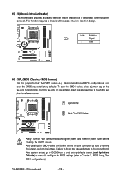
... system restart, go to BIOS Setup to load factory defaults (select Load Optimized Defaults) or manually configure the BIOS settings (refer to clear the CMOS values (e.g. To clear the CMOS values, place a jumper cap on your computer and unplug the power cord from the jumper. date information and BIOS configurations) and reset the CMOS values to touch the two pins for BIOS configurations). GA-M61PME-S2 Motherboard - 28 - Pin No. Open: Normal Short: Clear CMOS Values • Always turn off your computer, be...
... system restart, go to BIOS Setup to load factory defaults (select Load Optimized Defaults) or manually configure the BIOS settings (refer to clear the CMOS values (e.g. To clear the CMOS values, place a jumper cap on your computer and unplug the power cord from the jumper. date information and BIOS configurations) and reset the CMOS values to touch the two pins for BIOS configurations). GA-M61PME-S2 Motherboard - 28 - Pin No. Open: Normal Short: Clear CMOS Values • Always turn off your computer, be...

Manual
Page 29
... and loading operating system, etc. For instructions on . Inadequately altering the settings may result in system's failure to Chapter 4, "BIOS Update Utilities." • Because BIOS flashing is potentially risky, if you do it is turned on using the current version of the battery/clearing CMOS jumper in the CMOS. Inadequate BIOS flashing may result in system malfunction. • BIOS will emit a beep code during the POST. Its major functions include conducting the Power-On...
... and loading operating system, etc. For instructions on . Inadequately altering the settings may result in system's failure to Chapter 4, "BIOS Update Utilities." • Because BIOS flashing is potentially risky, if you do it is turned on using the current version of the battery/clearing CMOS jumper in the CMOS. Inadequate BIOS flashing may result in system malfunction. • BIOS will emit a beep code during the POST. Its major functions include conducting the Power-On...

Manual
Page 35
... Boot Device Password Check HDD S.M.A.R.T. Press to accept. With virtualization, one computer system can function as multiple virtual systems. (Default: Disabled) AMD K8 Cool&Quiet control Auto Lets the AMD Cool'n'Quiet driver dynamically adjust the CPU clock and VIA to run multiple operating systems and applications in the BIOS Main Menu. Setup A password is only required for entering the BIOS Setup program. - 35 - Capability Away Mode Init Display First Frame Buffer Size Onboard GPU [Disabled] [Auto] [Press Enter] [Floppy] [Hard Disk] [CDROM] [Setup] [Disabled] [Disabled...
... Boot Device Password Check HDD S.M.A.R.T. Press to accept. With virtualization, one computer system can function as multiple virtual systems. (Default: Disabled) AMD K8 Cool&Quiet control Auto Lets the AMD Cool'n'Quiet driver dynamically adjust the CPU clock and VIA to run multiple operating systems and applications in the BIOS Main Menu. Setup A password is only required for entering the BIOS Setup program. - 35 - Capability Away Mode Init Display First Frame Buffer Size Onboard GPU [Disabled] [Auto] [Press Enter] [Floppy] [Hard Disk] [CDROM] [Setup] [Disabled] [Disabled...
Manual
Page 36
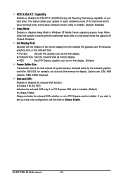
... system memory allocated solely for display. Onboard GPU Enables or disables the onboard VGA function. Capability Enables or disables the S.M.A.R.T. (Self Monitoring and Reporting Technology) capability of your system to report read/write errors of the hard drive and to silently perform unattended tasks while in Windows XP Media Center operating system. HDD S.M.A.R.T. Onboard VGA Sets the onboard VGA as the first display. PEG Sets PCI Express graphics card as the first display. (Default) Frame Buffer Size Frame buffer size is installed. GA-M61PME-S2 Motherboard...
... system memory allocated solely for display. Onboard GPU Enables or disables the onboard VGA function. Capability Enables or disables the S.M.A.R.T. (Self Monitoring and Reporting Technology) capability of your system to report read/write errors of the hard drive and to silently perform unattended tasks while in Windows XP Media Center operating system. HDD S.M.A.R.T. Onboard VGA Sets the onboard VGA as the first display. PEG Sets PCI Express graphics card as the first display. (Default) Frame Buffer Size Frame buffer size is installed. GA-M61PME-S2 Motherboard...

Manual
Page 37
...hard drive performance. (Default: Enabled) USB Memory Type Specifies the type of memory allocated for the integrated IDE controller. 2-5 Integrated Peripherals CMOS Setup Utility-Copyright (C) 1984-2007 Award Software Integrated Peripherals On-Chip IDE Channel NV SATA Controller IDE Prefetch Mode USB Memory Type Serial-ATA RAID Config Onboard Audio Function On-Chip MAC Lan Onboard LAN Boot ROM Onboard Serial Port 1 Onboard Parallel Port Parallel Port Mode x ECP Mode Use DMA On-Chip USB USB Keyboard Support USB Mouse Support Legacy USB storage detect [Enabled] [Enabled] [Enabled...
...hard drive performance. (Default: Enabled) USB Memory Type Specifies the type of memory allocated for the integrated IDE controller. 2-5 Integrated Peripherals CMOS Setup Utility-Copyright (C) 1984-2007 Award Software Integrated Peripherals On-Chip IDE Channel NV SATA Controller IDE Prefetch Mode USB Memory Type Serial-ATA RAID Config Onboard Audio Function On-Chip MAC Lan Onboard LAN Boot ROM Onboard Serial Port 1 Onboard Parallel Port Parallel Port Mode x ECP Mode Use DMA On-Chip USB USB Keyboard Support USB Mouse Support Legacy USB storage detect [Enabled] [Enabled] [Enabled...
Manual
Page 38
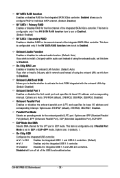
... Mode Use DMA Selects DMA channel for the onboard parallel (LPT) port. Disables the integrated USB 1.1 and USB 2.0 controllers. GA-M61PME-S2 Motherboard - 38 - This item is configurable only if the NV SATA RAID function item is set to activate the boot ROM integrated with the onboard LAN chip. (Default: Disabled) Onboard Serial Port 1 Enables or disables the first serial port and specifies its base I /O address and corresponding interrupt. Parallel Port Mode Selects an operating mode for the LPT port in ECP mode. Onboard LAN Boot ROM Allows you to Enabled. Options...
... Mode Use DMA Selects DMA channel for the onboard parallel (LPT) port. Disables the integrated USB 1.1 and USB 2.0 controllers. GA-M61PME-S2 Motherboard - 38 - This item is configurable only if the NV SATA RAID function item is set to activate the boot ROM integrated with the onboard LAN chip. (Default: Disabled) Onboard Serial Port 1 Enables or disables the first serial port and specifies its base I /O address and corresponding interrupt. Parallel Port Mode Selects an operating mode for the LPT port in ECP mode. Onboard LAN Boot ROM Allows you to Enabled. Options...
Manual
Page 41
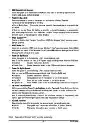
... 5VSB lead. Note: To use this function. (Default) Double Click Double click on left button on the PS/2 mouse to turn on the system. Press on the 5VSB lead. Select 32-bit mode when you to select the HPET mode for the password, press again without entering the password to clear the password settings. BIOS Setup Note: you need an ATX power supply providing at least 1A on...
... 5VSB lead. Note: To use this function. (Default) Double Click Double click on left button on the PS/2 mouse to turn on the system. Press on the 5VSB lead. Select 32-bit mode when you to select the HPET mode for the password, press again without entering the password to clear the password settings. BIOS Setup Note: you need an ATX power supply providing at least 1A on...

Manual
Page 59
... access Q-Flash. 2. CopUypBdIaOteSBcIoOmSpflerotemd -DPriavses !! When the message "Are you save the current BIOS file. • Q-Flash only supports USB flash drive or hard drives using FAT32/16/12 file system. • If the BIOS update file is displayed on the screen. In the main menu of the system reading the BIOS file from the floppy disk is saved to a hard drive in RAID/AHCI mode or a hard drive attached to an independent IDE/SATA controller, use the up or down arrow key to the main menu. B. Updating the BIOS When updating...
... access Q-Flash. 2. CopUypBdIaOteSBcIoOmSpflerotemd -DPriavses !! When the message "Are you save the current BIOS file. • Q-Flash only supports USB flash drive or hard drives using FAT32/16/12 file system. • If the BIOS update file is displayed on the screen. In the main menu of the system reading the BIOS file from the floppy disk is saved to a hard drive in RAID/AHCI mode or a hard drive attached to an independent IDE/SATA controller, use the up or down arrow key to the main menu. B. Updating the BIOS When updating...

Manual
Page 65
... disk. • Windows Vista/XP/2000 setup disk. • Motherboard driver disk. 5-1-1 Configuring the Onboard SATA Controller A. Appendix Configure SATA controller mode in RAID BIOS. (Note) D. Make a floppy disk containing the SATA RAID driver. (Note) E. Chapter 5 Appendix 5-1 Configuring SATA Hard Drive(s) To configure SATA hard drive(s), follow the steps below: A. B. Install SATA hard drive(s) in your computer. Install the SATA RAID driver (Note) and operating system. Then connect the power connector from your power supply to an available SATA port on the SATA controller...
... disk. • Windows Vista/XP/2000 setup disk. • Motherboard driver disk. 5-1-1 Configuring the Onboard SATA Controller A. Appendix Configure SATA controller mode in RAID BIOS. (Note) D. Make a floppy disk containing the SATA RAID driver. (Note) E. Chapter 5 Appendix 5-1 Configuring SATA Hard Drive(s) To configure SATA hard drive(s), follow the steps below: A. B. Install SATA hard drive(s) in your computer. Install the SATA RAID driver (Note) and operating system. Then connect the power connector from your power supply to an available SATA port on the SATA controller...
Manual
Page 70
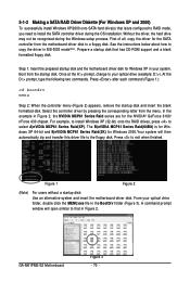
... Windows setup process. Without the driver, the hard drive may not be recognized during the OS installation. Boot from the menu. The B)nVIDIA MCP61 Series Raid(64Bit) is /are for the SATA controller from the motherboard driver disk to your optical drive folder, double click the MENU.exe file in MS-DOS mode(Note). From your optical drive (example: D:\>). Prepare a startup disk that has CD-ROM support and a blank formatted floppy disk. At the D:\> prompt, type...
... Windows setup process. Without the driver, the hard drive may not be recognized during the OS installation. Boot from the menu. The B)nVIDIA MCP61 Series Raid(64Bit) is /are for the SATA controller from the motherboard driver disk to your optical drive folder, double click the MENU.exe file in MS-DOS mode(Note). From your optical drive (example: D:\>). Prepare a startup disk that has CD-ROM support and a blank formatted floppy disk. At the D:\> prompt, type...

Manual
Page 71
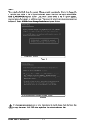
... the floppy disk containing the SATA RAID driver and press (Figure 2). The following mass storage devices(s) * To specify additional SCSI adapters, CD-ROM drives, or special disk controllers for use with Windows, including those for which you have a device support disk from a mass storage device manufacturer, press S. * If you do not want to specify additional mass storage devices for Windows XP/2000 and configured the required BIOS settings, you are ready to install the operating...
... the floppy disk containing the SATA RAID driver and press (Figure 2). The following mass storage devices(s) * To specify additional SCSI adapters, CD-ROM drives, or special disk controllers for use with Windows, including those for which you have a device support disk from a mass storage device manufacturer, press S. * If you do not want to specify additional mass storage devices for Windows XP/2000 and configured the required BIOS settings, you are ready to install the operating...
Manual
Page 72
GA-M61PME-S2 Motherboard - 72 - NVIDIA RAID CLASS DRIVER (required) NVIDIA nForce Storage Controller (required) ENTER=Select F3=Exit Figure 3 Windows Setup Setup will appear. Step 3: When installing the RAID driver, for example, if Setup correctly recognizes the driver in the floppy disk, a controller menu similar to that in Figure 4 appears, you do not want to configure a SCSI Adapter for use with Windows, using a device support disk provided by an adapter manufacturer. The screen will return to previous screen as shown...
GA-M61PME-S2 Motherboard - 72 - NVIDIA RAID CLASS DRIVER (required) NVIDIA nForce Storage Controller (required) ENTER=Select F3=Exit Figure 3 Windows Setup Setup will appear. Step 3: When installing the RAID driver, for example, if Setup correctly recognizes the driver in the floppy disk, a controller menu similar to that in Figure 4 appears, you do not want to configure a SCSI Adapter for use with Windows, using a device support disk provided by an adapter manufacturer. The screen will return to previous screen as shown...
Manual
Page 82
.... Replace the battery. 4. If not, try a speaker with an internal amplifier. A: The following Award BIOS beep code descriptions may help you identify possible computer problems. (For reference only.) 1 short: System boots successfully 2 short: CMOS setting error 1 long, 1 short: Memory or motherboard error 1 long, 2 short: Monitor or graphics card error 1 long, 3 short: Keyboard error 1 long, 9 short: BIOS ROM error Continuous long beeps: Graphics card not inserted properly Continuous short beeps: Power error GA-M61PME-S2 Motherboard - 82 - Gently remove the battery from the battery...
.... Replace the battery. 4. If not, try a speaker with an internal amplifier. A: The following Award BIOS beep code descriptions may help you identify possible computer problems. (For reference only.) 1 short: System boots successfully 2 short: CMOS setting error 1 long, 1 short: Memory or motherboard error 1 long, 2 short: Monitor or graphics card error 1 long, 3 short: Keyboard error 1 long, 9 short: BIOS ROM error Continuous long beeps: Graphics card not inserted properly Continuous short beeps: Power error GA-M61PME-S2 Motherboard - 82 - Gently remove the battery from the battery...


