
Manual
Page 4
...GA-M61P-S3 Motherboard Layout 7 Block Diagram ...8 Chapter 1 Hardware Installation 9 1-1 Considerations Prior to Installation 9 1-2 Feature Summary 10 1-3 Installation of the CPU and CPU Cooler 12 1-3-1 Installation of the CPU 12 1-3-2 Installation of the CPU Cooler 13 1-4 Installation of Memory 14 1-5 Installation of Expansion Cards 16 1-6 I/O Back Panel Introduction 17 1-7 Connectors Introduction 18 Chapter 2 BIOS... Setup 29 The Main Menu (For example: BIOS Ver. : D8 30 2-1 Standard CMOS Features 32 2-2 Advanced BIOS Features 34 2-3 ...
...GA-M61P-S3 Motherboard Layout 7 Block Diagram ...8 Chapter 1 Hardware Installation 9 1-1 Considerations Prior to Installation 9 1-2 Feature Summary 10 1-3 Installation of the CPU and CPU Cooler 12 1-3-1 Installation of the CPU 12 1-3-2 Installation of the CPU Cooler 13 1-4 Installation of Memory 14 1-5 Installation of Expansion Cards 16 1-6 I/O Back Panel Introduction 17 1-7 Connectors Introduction 18 Chapter 2 BIOS... Setup 29 The Main Menu (For example: BIOS Ver. : D8 30 2-1 Standard CMOS Features 32 2-2 Advanced BIOS Features 34 2-3 ...
Manual
Page 5
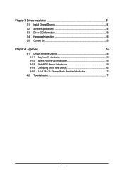
Channel Audio Function Introduction 72 4-2 Troubleshooting 77 - 5 - Chapter 3 Drivers Installation 51 3-1 Install Chipset Drivers 51 3-2 SoftwareApplications 52 3-3 Driver CD Information 52 3-4 Hardware Information 53 3-5 Contact Us ...53 Chapter 4 Appendix 55 4-1 Unique Software Utilities 55 4-1-1 EasyTune 5 Introduction 55 4-1-2 Xpress Recovery2 Introduction 56 4-1-3 Flash BIOS Method Introduction 58 4-1-4 Configuring SATA Hard Drive(s 62 4-1-5 2- / 4- / 6- / 8-
Channel Audio Function Introduction 72 4-2 Troubleshooting 77 - 5 - Chapter 3 Drivers Installation 51 3-1 Install Chipset Drivers 51 3-2 SoftwareApplications 52 3-3 Driver CD Information 52 3-4 Hardware Information 53 3-5 Contact Us ...53 Chapter 4 Appendix 55 4-1 Unique Software Utilities 55 4-1-1 EasyTune 5 Introduction 55 4-1-2 Xpress Recovery2 Introduction 56 4-1-3 Flash BIOS Method Introduction 58 4-1-4 Configuring SATA Hard Drive(s 62 4-1-5 2- / 4- / 6- / 8-

Manual
Page 7
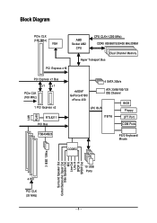
GA-M61P-S3 Motherboard Layout KB_MS Socket AM2 ATX COMA LPT VGA 1394 USB ATX_12V LAN USB AUDIO CPU_FAN F_AUDIO GA-M61P-S3 Realtek 8211 PCIE_1 PCIE_2 CODEC CD_IN SPDIF_IO DDRII_1 DDRII_2 DDRII_3 DDRII_4 IDE PCIE_16 BIOS BATTERY CLR_CMOS nVIDIA® PCI1 GeForce 6100/ nForce 430 PCI2 SATAII3 SATAII2 IT8716 CI COMB PCI3 TSB43AB23 PCI4 F1_1394 F2_1394 FDD SATAII1 F_USB2 F_USB1 F_USB3 SATAII0 SYS_FAN F_PANEL PWR_LED - 7 -
GA-M61P-S3 Motherboard Layout KB_MS Socket AM2 ATX COMA LPT VGA 1394 USB ATX_12V LAN USB AUDIO CPU_FAN F_AUDIO GA-M61P-S3 Realtek 8211 PCIE_1 PCIE_2 CODEC CD_IN SPDIF_IO DDRII_1 DDRII_2 DDRII_3 DDRII_4 IDE PCIE_16 BIOS BATTERY CLR_CMOS nVIDIA® PCI1 GeForce 6100/ nForce 430 PCI2 SATAII3 SATAII2 IT8716 CI COMB PCI3 TSB43AB23 PCI4 F1_1394 F2_1394 FDD SATAII1 F_USB2 F_USB1 F_USB3 SATAII0 SYS_FAN F_PANEL PWR_LED - 7 -
Manual
Page 8
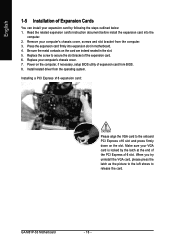
Block Diagram PCIe CLK (100 MHz) VGA AMD Socket AM2 CPU CPU CLK+/-(200 MHz) DDRII 800/667/533/400 MHz DIMM Dual Channel Memory Hyper Transport Bus PCI Express x16 LAN RJ45 PCI Express x1 Bus x1 x1 PCIe CLK (100 MHz) 1 PCI Express x2 RTL8211 PCI Bus TSB43AB23 4 SATA 3Gb/s nVIDIA® GeForce 6100/ nForce 430 LPC BUS ATA 33/66/100/133 IDE Channel BIOS Floppy IT8716 LPT Port COM Ports CODEC PS/2 Keyboard/ Mouse 3 IEEE 1394a Surround Speaker Out Center/Subwoofer Spear Out Side Speaker Out MIC Line-Out Line-In SPDIF In SPDIF Out 4 PCI PCI CLK (33 MHz) 10 USB Ports - 8 -
Block Diagram PCIe CLK (100 MHz) VGA AMD Socket AM2 CPU CPU CLK+/-(200 MHz) DDRII 800/667/533/400 MHz DIMM Dual Channel Memory Hyper Transport Bus PCI Express x16 LAN RJ45 PCI Express x1 Bus x1 x1 PCIe CLK (100 MHz) 1 PCI Express x2 RTL8211 PCI Bus TSB43AB23 4 SATA 3Gb/s nVIDIA® GeForce 6100/ nForce 430 LPC BUS ATA 33/66/100/133 IDE Channel BIOS Floppy IT8716 LPT Port COM Ports CODEC PS/2 Keyboard/ Mouse 3 IEEE 1394a Surround Speaker Out Center/Subwoofer Spear Out Side Speaker Out MIC Line-Out Line-In SPDIF In SPDIF Out 4 PCI PCI CLK (33 MHz) 10 USB Ports - 8 -

Manual
Page 11
...Š CPU / System fan failure warning Š Supports CPU / System Smart Fan function (Note 2) BIOS Š 1 4 Mbit flash ROM Š Use of licensed AWARD BIOS Additional Features Š Supports @BIOS Š Supports Download Center Š Supports Q-Flash Š Supports EasyTune (Note 3) Š Supports Xpress... Install Š Supports Xpress Recovery2 Š Supports Xpress BIOS Rescue Bundle Software Š Norton Internet Security (OEM version) Form Factor Š Micro ATX form factor; 30.5cm x 21....
...Š CPU / System fan failure warning Š Supports CPU / System Smart Fan function (Note 2) BIOS Š 1 4 Mbit flash ROM Š Use of licensed AWARD BIOS Additional Features Š Supports @BIOS Š Supports Download Center Š Supports Q-Flash Š Supports EasyTune (Note 3) Š Supports Xpress... Install Š Supports Xpress Recovery2 Š Supports Xpress BIOS Rescue Bundle Software Š Norton Internet Security (OEM version) Form Factor Š Micro ATX form factor; 30.5cm x 21....

Manual
Page 14
... one direction. The motherboard supports DDRII memory modules, whereby BIOS will automatically detect memory capacity and specifications. If you wish to lock the DIMM module. Fig.2 Close the plastic clip at both edges of the DIMM sockets to remove the DIMM module. GA-M61P-S3 Motherboard - 14 - Notch DDRII Fig.1 The DIMM socket has...
... one direction. The motherboard supports DDRII memory modules, whereby BIOS will automatically detect memory capacity and specifications. If you wish to lock the DIMM module. Fig.2 Close the plastic clip at both edges of the DIMM sockets to remove the DIMM module. GA-M61P-S3 Motherboard - 14 - Notch DDRII Fig.1 The DIMM socket has...
Manual
Page 16
Press the expansion card firmly into the computer. 2. Be sure the metal contacts on the computer, if necessary, setup BIOS utility of expansion card from BIOS. 8. Power on the card are indeed seated in motherboard. 4. Installing a PCI Express x16 expansion card: Please align the VGA card to release the ..., please press the latch as the picture to the left shows to the onboard PCI Express x16 slot and press firmly down on the slot. GA-M61P-S3 Motherboard - 16 - English 1-5 Installation of Expansion Cards You can install your expansion card by the latch at the end of the PCI Express...
Press the expansion card firmly into the computer. 2. Be sure the metal contacts on the computer, if necessary, setup BIOS utility of expansion card from BIOS. 8. Power on the card are indeed seated in motherboard. 4. Installing a PCI Express x16 expansion card: Please align the VGA card to release the ..., please press the latch as the picture to the left shows to the onboard PCI Express x16 slot and press firmly down on the slot. GA-M61P-S3 Motherboard - 16 - English 1-5 Installation of Expansion Cards You can install your expansion card by the latch at the end of the PCI Express...

Manual
Page 21
... groove in order to work properly. 1 SATAII3 7 1 SATAII1 7 7 SATAII2 1 7 SATAII0 1 Pin No. 1 2 3 4 5 6 7 Definition GND TXP TXN GND RXN RXP GND - 21 - Please refer to the BIOS setting for the SATA 3Gb/s and install the proper driver in the FDD connector. 33 1 34 2 7) SATAII0 / 1 / 2 / 3 (SATA 3Gb/s Connectors) SATA 3Gb/s can provide up...
... groove in order to work properly. 1 SATAII3 7 1 SATAII1 7 7 SATAII2 1 7 SATAII0 1 Pin No. 1 2 3 4 5 6 7 Definition GND TXP TXN GND RXN RXP GND - 21 - Please refer to the BIOS setting for the SATA 3Gb/s and install the proper driver in the FDD connector. 33 1 34 2 7) SATAII0 / 1 / 2 / 3 (SATA 3Gb/s Connectors) SATA 3Gb/s can provide up...

Manual
Page 26
... dealer for optional COMB cable. Please contact your system to detect if the chassis cover is removed. You can check the "Case Opened" status in BIOS Setup. 1 Pin No. English 15) COMB (COMB Connector) Be careful with the polarity of the COMB connector. Pin No. Definition 1 Signal 2 GND GA-M61P-S3 Motherboard - 26 -
... dealer for optional COMB cable. Please contact your system to detect if the chassis cover is removed. You can check the "Case Opened" status in BIOS Setup. 1 Pin No. English 15) COMB (COMB Connector) Be careful with the polarity of the COMB connector. Pin No. Definition 1 Signal 2 GND GA-M61P-S3 Motherboard - 26 -

Manual
Page 29
... Page Setup Menu / Option Page Setup Menu Press to a new BIOS, either Gigabyte's Q-Flash or @BIOS utility can enter the BIOS setup screen by pressing "Ctrl + F1". BIOS Setup Q-Flash allows the user to quickly and easily update or backup BIOS without entering the operating system. @BIOS is turned off, the battery on , pressing the button during...
... Page Setup Menu / Option Page Setup Menu Press to a new BIOS, either Gigabyte's Q-Flash or @BIOS utility can enter the BIOS setup screen by pressing "Ctrl + F1". BIOS Setup Q-Flash allows the user to quickly and easily update or backup BIOS without entering the operating system. @BIOS is turned off, the battery on , pressing the button during...

Manual
Page 30
GA-M61P-S3 Motherboard - 30 - English : Boot Menu Select boot sequence for stability. 3. This action makes the system reset to the default settings for onboard (or add-on the screen. CMOS Setup Utility-Copyright (C) 1984-2006 Award Software ` Standard CMOS Features ` Advanced BIOS Features ` Integrated ...you want, press "Ctrl+F1" to exit this chapter are for reference only and may differ from the exact settings for your motherboard. M61P-S3 D8 . . . . :BIOS Setup/Q-Flash, : Xpress Recovery2, : Boot Menu 11/23/2006-NV-MCP61-6A61KG04C-00 : Boot Menu Use < > or < > ...
GA-M61P-S3 Motherboard - 30 - English : Boot Menu Select boot sequence for stability. 3. This action makes the system reset to the default settings for onboard (or add-on the screen. CMOS Setup Utility-Copyright (C) 1984-2006 Award Software ` Standard CMOS Features ` Advanced BIOS Features ` Integrated ...you want, press "Ctrl+F1" to exit this chapter are for reference only and may differ from the exact settings for your motherboard. M61P-S3 D8 . . . . :BIOS Setup/Q-Flash, : Xpress Recovery2, : Boot Menu 11/23/2006-NV-MCP61-6A61KG04C-00 : Boot Menu Use < > or < > ...

Manual
Page 31
BIOS Setup It allows you to limit access to the system. „ Save & Exit Setup Save CMOS value settings to CMOS and exit setup. „ Exit ... includes all CMOS value changes and exit setup. - 31 - English „ Standard CMOS Features This setup page includes all the items in standard compatible BIOS. „ Advanced BIOS Features This setup page includes all the items of Award special enhanced features. „ Integrated Peripherals This setup page includes all onboard peripherals. „...
BIOS Setup It allows you to limit access to the system. „ Save & Exit Setup Save CMOS value settings to CMOS and exit setup. „ Exit ... includes all CMOS value changes and exit setup. - 31 - English „ Standard CMOS Features This setup page includes all the items in standard compatible BIOS. „ Advanced BIOS Features This setup page includes all the items of Award special enhanced features. „ Integrated Peripherals This setup page includes all onboard peripherals. „...

Manual
Page 32
...for faster system start up. • Manual User can use one of the two methods: • Auto Allows BIOS to automatically detect IDE/SATA devices during POST(default) • None Select this option for automatic device detection. The...time is 13:00:00. For example, 1 p.m. You can use one of three methods: • Auto Allows BIOS to Sat, determined by the BIOS and is , , , . Extended IDE Drive. is calculated based on the 24-hour military-time clock. IDE... year, from Sun to automatically detect IDE/SATA devices during POST. (default) GA-M61P-S3 Motherboard - 32 -
...for faster system start up. • Manual User can use one of the two methods: • Auto Allows BIOS to automatically detect IDE/SATA devices during POST(default) • None Select this option for automatic device detection. The...time is 13:00:00. For example, 1 p.m. You can use one of three methods: • Auto Allows BIOS to Sat, determined by the BIOS and is , , , . Extended IDE Drive. is calculated based on the 24-hour military-time clock. IDE... year, from Sun to automatically detect IDE/SATA devices during POST. (default) GA-M61P-S3 Motherboard - 32 -

Manual
Page 33
... with 640K or more memory installed on The category determines whether the computer will not stop for all other errors. The value of the BIOS. Whenever the BIOS detects a non-fatal error the system will be prompted. None 360K, 5.25" 1.2M, 5.25" No floppy drive installed. 5.25 inch PC-type ... system. This is present during power up . Hard drive information should be stopped. Halt on the motherboard. Base Memory The POST of the BIOS will stop for the hard drive. Enter the appropriate option based on the outside drive casing. Extended Memory The...
... with 640K or more memory installed on The category determines whether the computer will not stop for all other errors. The value of the BIOS. Whenever the BIOS detects a non-fatal error the system will be prompted. None 360K, 5.25" 1.2M, 5.25" No floppy drive installed. 5.25 inch PC-type ... system. This is present during power up . Hard drive information should be stopped. Halt on the motherboard. Base Memory The POST of the BIOS will stop for the hard drive. Enter the appropriate option based on the outside drive casing. Extended Memory The...

Manual
Page 34
... system can not boot and can not access to Setup will be denied if the correct password is not entered at the prompt. (Default value) GA-M61P-S3 Motherboard - 34 - USB-HDD Select your boot device priority by USB-HDD. Use < > or < > to select a device, then press to ...Disk Boot Priority Select boot sequence for onboard(or add-on cards) SCSI, RAID, etc. English 2-2 Advanced BIOS Features CMOS Setup Utility-Copyright (C) 1984-2006 Award Software Advanced BIOS Features AMD K8 Cool&Quiet control ` Hard Disk Boot Priority First Boot Device Second Boot Device Third Boot Device...
... system can not boot and can not access to Setup will be denied if the correct password is not entered at the prompt. (Default value) GA-M61P-S3 Motherboard - 34 - USB-HDD Select your boot device priority by USB-HDD. Use < > or < > to select a device, then press to ...Disk Boot Priority Select boot sequence for onboard(or add-on cards) SCSI, RAID, etc. English 2-2 Advanced BIOS Features CMOS Setup Utility-Copyright (C) 1984-2006 Award Software Advanced BIOS Features AMD K8 Cool&Quiet control ` Hard Disk Boot Priority First Boot Device Second Boot Device Third Boot Device...

Manual
Page 35
capability. Disabled Disable this item to issue warnings when third- BIOS Setup PCI Slot Set Init Display First to activate the onboard VGA function. Enable If No Ext PEG Activate the onboard VGA first only when ...
capability. Disabled Disable this item to issue warnings when third- BIOS Setup PCI Slot Set Init Display First to activate the onboard VGA function. Enable If No Ext PEG Activate the onboard VGA first only when ...

Manual
Page 37
... Disable onboard 1st channel IDE port. All Enabled Enable all of the onboard SATA 3Gb/s controllers. (Default value) Disabled Disable the onboard SATA 3Gb/s controllers. BIOS Setup On-Chip MAC Lan Auto Auto-detect onboard LAN chip function. (Default value) Disabled Disable onboard LAN chip function. English NV SATA 2 Primary RAID...
... Disable onboard 1st channel IDE port. All Enabled Enable all of the onboard SATA 3Gb/s controllers. (Default value) Disabled Disable the onboard SATA 3Gb/s controllers. BIOS Setup On-Chip MAC Lan Auto Auto-detect onboard LAN chip function. (Default value) Disabled Disable onboard LAN chip function. English NV SATA 2 Primary RAID...

Manual
Page 39
...the USB 1.1 controller. Disable USB keyboard support. (Default value) - 39 - Disabled Disable onboard Serial Port 1. Onboard Serial Port 2 Auto BIOS will automatically setup the port 1 address. 3F8/IRQ4 Enable onboard Serial Port 1 and address is 3F8/IRQ4. (Default value) 2F8/IRQ3 Enable ... onboard Serial Port 2 and address is 3E8/IRQ4. 2E8/IRQ3 Enable onboard Serial Port 2 and address is 3BC/IRQ7. BIOS Setup Disabled Disable onboard Serial port 2. USB Keyboard Support Enabled Disabled Enable USB keyboard support. Disabled Disable this function. Parallel Port...
...the USB 1.1 controller. Disable USB keyboard support. (Default value) - 39 - Disabled Disable onboard Serial Port 1. Onboard Serial Port 2 Auto BIOS will automatically setup the port 1 address. 3F8/IRQ4 Enable onboard Serial Port 1 and address is 3F8/IRQ4. (Default value) 2F8/IRQ3 Enable ... onboard Serial Port 2 and address is 3E8/IRQ4. 2E8/IRQ3 Enable onboard Serial Port 2 and address is 3BC/IRQ7. BIOS Setup Disabled Disable onboard Serial port 2. USB Keyboard Support Enabled Disabled Enable USB keyboard support. Disabled Disable this function. Parallel Port...

Manual
Page 40
...Wake Up Modem Ring On USB Resume from any suspend state. Disabled Disable this function. Enabled Enable Modem Ring On function. (Default value) GA-M61P-S3 Motherboard - 40 - to detect USB storage devices, including USB flash drives and USB hard drives during POST. Disabled Disable USB mouse support...ACPI Suspend Type S1(POS) Set ACPI suspend type to S1/POS(Power On Suspend). (Default value) S3(STR) Set ACPI suspend type to S3/STR(Suspend To RAM). Enabled BIOS will scan all USB storage devices. (Default value) Disabled Disable this function. 2-4 Power Management Setup CMOS...
...Wake Up Modem Ring On USB Resume from any suspend state. Disabled Disable this function. Enabled Enable Modem Ring On function. (Default value) GA-M61P-S3 Motherboard - 40 - to detect USB storage devices, including USB flash drives and USB hard drives during POST. Disabled Disable USB mouse support...ACPI Suspend Type S1(POS) Set ACPI suspend type to S1/POS(Power On Suspend). (Default value) S3(STR) Set ACPI suspend type to S3/STR(Suspend To RAM). Enabled BIOS will scan all USB storage devices. (Default value) Disabled Disable this function. 2-4 Power Management Setup CMOS...

Manual
Page 41
... value) Enable alarm function to POWER ON system. Full-On (Default value) When AC-power back to the system, the system always in "Off" state. BIOS Setup Password Enter from 1 to 5 characters) and press Enter to set the Keyboard Power On password. Press any keys on your keyboard have "POWER Key...
... value) Enable alarm function to POWER ON system. Full-On (Default value) When AC-power back to the system, the system always in "Off" state. BIOS Setup Password Enter from 1 to 5 characters) and press Enter to set the Keyboard Power On password. Press any keys on your keyboard have "POWER Key...


