
Manual
Page 4
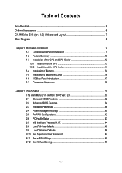
... the CPU 12 1-3-2 Installation of the CPU Cooler 13 1-4 Installation of Memory 14 1-5 Installation of Expansion Cards 16 1-6 I/O Back Panel Introduction 17 1-7 Connectors Introduction 18 Chapter 2 BIOS Setup 29 The Main Menu (For example: BIOS Ver.: D3 30 2-1 Standard CMOS Features 32 2-2 Advanced BIOS Features 34 2-3 IntegratedPeripherals 36 2-4 Power Management Setup 40 2-5 PnP/PCI Configurations 42 2-6 PC Health Status 43 2-7 MB Intelligent Tweaker(M.I.T 44 2-8 Load Fail-Safe Defaults 46 2-9 Load Optimized Defaults 46 2-10 Set Supervisor/User Password...
... the CPU 12 1-3-2 Installation of the CPU Cooler 13 1-4 Installation of Memory 14 1-5 Installation of Expansion Cards 16 1-6 I/O Back Panel Introduction 17 1-7 Connectors Introduction 18 Chapter 2 BIOS Setup 29 The Main Menu (For example: BIOS Ver.: D3 30 2-1 Standard CMOS Features 32 2-2 Advanced BIOS Features 34 2-3 IntegratedPeripherals 36 2-4 Power Management Setup 40 2-5 PnP/PCI Configurations 42 2-6 PC Health Status 43 2-7 MB Intelligent Tweaker(M.I.T 44 2-8 Load Fail-Safe Defaults 46 2-9 Load Optimized Defaults 46 2-10 Set Supervisor/User Password...
Manual
Page 10
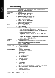
...CPU Š Socket AM2 for additional 2 ports by cable Š 1 power LED connector Š 1 Chassis Intrusion connector GA-M55plus-S3G (rev. 3.0) Motherboard - 10 - Supports data striping (RAID 0), mirroring (RAID 1), striping+mirroring (RAID 0+1), and RAID 5 for Serial ATA O.S Support Š Microsoft Windows 2000/XP Memory Š 4 DDRII DIMM memory slots (supports up to 16 GB memory) (Note 1) Š Supports dual channel DDRII 800/667/533/400 DIMMs Š Supports 1.8V DDRII DIMMs Expanstion Slots Š 1 PCI Express x16 slot Š 2 PCI Express x1 slots Š 4 PCI slots...
...CPU Š Socket AM2 for additional 2 ports by cable Š 1 power LED connector Š 1 Chassis Intrusion connector GA-M55plus-S3G (rev. 3.0) Motherboard - 10 - Supports data striping (RAID 0), mirroring (RAID 1), striping+mirroring (RAID 0+1), and RAID 5 for Serial ATA O.S Support Š Microsoft Windows 2000/XP Memory Š 4 DDRII DIMM memory slots (supports up to 16 GB memory) (Note 1) Š Supports dual channel DDRII 800/667/533/400 DIMMs Š Supports 1.8V DDRII DIMMs Expanstion Slots Š 1 PCI Express x16 slot Š 2 PCI Express x1 slots Š 4 PCI slots...
Manual
Page 18
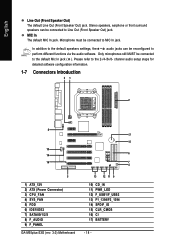
... must be connected to perform different functions via the audio software. channel audio setup steps for detailed software configuration information. 1-7 Connectors Introduction 31 2 8 17 15 10 14 6 16 7 4 5 1) ATX_12V 2) ATX (Power Connector) 3) CPU_FAN 4) SYS_FAN 5) FDD 6) IDE1/IDE2 7) SATAII0/1/2/3 8) F_AUDIO 9) F_PANEL GA-M55plus-S3G (rev. 3.0) Motherboard 13 12 11 9 10) CD_IN 11) PWR_LED 12) F_USB1/F_USB2 13) F1_1394/F2_1394 14) SPDIF_IO 15) CLR_CMOS 16) CI 17) BATTERY - 18...
... must be connected to perform different functions via the audio software. channel audio setup steps for detailed software configuration information. 1-7 Connectors Introduction 31 2 8 17 15 10 14 6 16 7 4 5 1) ATX_12V 2) ATX (Power Connector) 3) CPU_FAN 4) SYS_FAN 5) FDD 6) IDE1/IDE2 7) SATAII0/1/2/3 8) F_AUDIO 9) F_PANEL GA-M55plus-S3G (rev. 3.0) Motherboard 13 12 11 9 10) CD_IN 11) PWR_LED 12) F_USB1/F_USB2 13) F1_1394/F2_1394 14) SPDIF_IO 15) CLR_CMOS 16) CI 17) BATTERY - 18...
Manual
Page 20
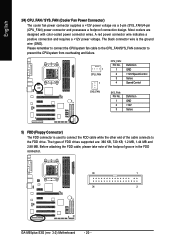
... types of FDD drives supported are designed with color-coded power connector wires. The black connector wire is used to connect the FDD cable while the other end of the foolproof groove in the FDD connector. 33 1 34 2 GA-M55plus-S3G (rev. 3.0) Motherboard - 20 - Before attaching the FDD cable, please take note of the cable connects to the FDD drive. English 3/4) CPU_FAN / SYS_FAN (Cooler Fan Power Connector) The cooler fan power connector supplies a +12V power voltage via a 3-pin (SYS_FAN)/4-pin (CPU_FAN) power connector and...
... types of FDD drives supported are designed with color-coded power connector wires. The black connector wire is used to connect the FDD cable while the other end of the foolproof groove in the FDD connector. 33 1 34 2 GA-M55plus-S3G (rev. 3.0) Motherboard - 20 - Before attaching the FDD cable, please take note of the cable connects to the FDD drive. English 3/4) CPU_FAN / SYS_FAN (Cooler Fan Power Connector) The cooler fan power connector supplies a +12V power voltage via a 3-pin (SYS_FAN)/4-pin (CPU_FAN) power connector and...

Manual
Page 21
... IDE connector. 40 39 2 1 IDE1 IDE2 7) SATAII0/1/2/3 (SATA 3Gb/s Connectors) SATA 3Gb/s can then connect to connect two IDE devices, please set the jumper on the IDE device). If you wish to two IDE devices (hard drive or optical drive). Hardware Installation Please refer to the BIOS setting for information on settings, please refer to the instructions located on one IDE cable, and the single IDE cable can provide up to the computer via an IDE connector. English 6) IDE1/2 (IDE Connector) An IDE device connects...
... IDE connector. 40 39 2 1 IDE1 IDE2 7) SATAII0/1/2/3 (SATA 3Gb/s Connectors) SATA 3Gb/s can then connect to connect two IDE devices, please set the jumper on the IDE device). If you wish to two IDE devices (hard drive or optical drive). Hardware Installation Please refer to the BIOS setting for information on settings, please refer to the instructions located on one IDE cable, and the single IDE cable can provide up to the computer via an IDE connector. English 6) IDE1/2 (IDE Connector) An IDE device connects...
Manual
Page 22
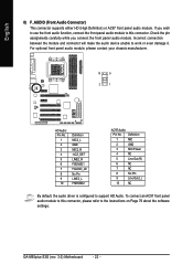
GA-M55plus-S3G (rev. 3.0) Motherboard - 22 - For optional front panel audio module, please contact your chassis manufacturer. 10 9 2 1 HD Audio: Pin No. 1 2 3 4 5 6 7 8 9 10 Definition MIC2_L GND MIC2_R -ACZ_DET LINE2_R FSENSE1 FAUDIO_JD No Pin LINE2_L FSENSE2 AC'97 Audio: Pin No. Definition 1 MIC 2 GND 3 MIC Power 4 NC 5 Line Out (R) 6 NC 7 NC 8 No Pin 9 Line Out (L) 10 NC By default, the audio driver is configured to work or even damage it. Incorrect connection between...
GA-M55plus-S3G (rev. 3.0) Motherboard - 22 - For optional front panel audio module, please contact your chassis manufacturer. 10 9 2 1 HD Audio: Pin No. 1 2 3 4 5 6 7 8 9 10 Definition MIC2_L GND MIC2_R -ACZ_DET LINE2_R FSENSE1 FAUDIO_JD No Pin LINE2_L FSENSE2 AC'97 Audio: Pin No. Definition 1 MIC 2 GND 3 MIC Power 4 NC 5 Line Out (R) 6 NC 7 NC 8 No Pin 9 Line Out (L) 10 NC By default, the audio driver is configured to work or even damage it. Incorrect connection between...
Manual
Page 26
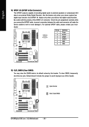
... clear CMOS, temporarily short the two pins. Open: Normal Short: Clear CMOS GA-M55plus-S3G (rev. 3.0) Motherboard - 26 - Check the pin assignment carefully while you connect the S/PDIF cable, incorrect connection between the cable and connector will make the device unable to its default values by this feature only when your stereo system has digital input function. Use this header. Use S/PDIF IN feature only when your local dealer. 1 2 5 6 Pin No. 1 2 3 4 5 6 Definition Power No Pin SPDIF...
... clear CMOS, temporarily short the two pins. Open: Normal Short: Clear CMOS GA-M55plus-S3G (rev. 3.0) Motherboard - 26 - Check the pin assignment carefully while you connect the S/PDIF cable, incorrect connection between the cable and connector will make the device unable to its default values by this feature only when your stereo system has digital input function. Use this header. Use S/PDIF IN feature only when your local dealer. 1 2 5 6 Pin No. 1 2 3 4 5 6 Definition Power No Pin SPDIF...
Manual
Page 32
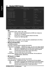
... to select this if no IDE/SATA devices are used and the system will skip the automatic detection step and allow for faster system start up . Jan. For example, 1 p.m. Manual User can use one of the two methods: Auto Allows BIOS to set the access mode for automatic device detection. GA-M55plus-S3G (rev. 3.0) Motherboard - 32 - English 2-1 Standard CMOS Features CMOS Setup Utility-Copyright (C) 1984-2006 Award Software Standard CMOS Features Date (mm:dd:yy...
... to select this if no IDE/SATA devices are used and the system will skip the automatic detection step and allow for faster system start up . Jan. For example, 1 p.m. Manual User can use one of the two methods: Auto Allows BIOS to set the access mode for automatic device detection. GA-M55plus-S3G (rev. 3.0) Motherboard - 32 - English 2-1 Standard CMOS Features CMOS Setup Utility-Copyright (C) 1984-2006 Award Software Standard CMOS Features Date (mm:dd:yy...
Manual
Page 34
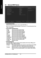
... tracks. Disabled BIOS will determine the floppy disk drive installed is 40 or 80 tracks. 360K type is 360K. (Default value) GA-M55plus-S3G (rev. 3.0) Motherboard - 34 - Note that BIOS can not tell from 720K, 1.2M or 1.44M drive type as they are all 80 tracks. USB-FDD Select your boot device priority by track number. Capability Away Mode Init Display First Frame Buffer Size Onboard GPU [Press Enter] [Floppy] [Hard Disk] [CDROM] [Disabled] [Setup] [Disabled] [Disabled] [PEG] [64M] [Enable If...
... tracks. Disabled BIOS will determine the floppy disk drive installed is 40 or 80 tracks. 360K type is 360K. (Default value) GA-M55plus-S3G (rev. 3.0) Motherboard - 34 - Note that BIOS can not tell from 720K, 1.2M or 1.44M drive type as they are all 80 tracks. USB-FDD Select your boot device priority by track number. Capability Away Mode Init Display First Frame Buffer Size Onboard GPU [Press Enter] [Floppy] [Hard Disk] [CDROM] [Disabled] [Setup] [Disabled] [Disabled] [PEG] [64M] [Enable If...

Manual
Page 35
... monitor utility is installed. Onboard GPU This item allows the user to decide when to PCI VGA card. Enabled Enable HDD S.M.A.R.T. capability. PCI Slot Set Init Display First to activate the onboard VGA function. BIOS Setup English Password Check System The system can not boot and can not access to Setup page will be denied if the Setup correct password is not entered at the prompt. (Default value) HDD S.M.A.R.T. If you install a PCI card and a PCI Express VGA card on -chip frame buffer size to 128 MB. Disabled Disable HDD...
... monitor utility is installed. Onboard GPU This item allows the user to decide when to PCI VGA card. Enabled Enable HDD S.M.A.R.T. capability. PCI Slot Set Init Display First to activate the onboard VGA function. BIOS Setup English Password Check System The system can not boot and can not access to Setup page will be denied if the Setup correct password is not entered at the prompt. (Default value) HDD S.M.A.R.T. If you install a PCI card and a PCI Express VGA card on -chip frame buffer size to 128 MB. Disabled Disable HDD...
Manual
Page 43
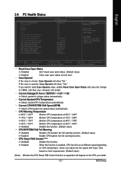
.../ 176oF Monitor CPU temperature at 80oC / 176oF. 90oC / 194oF Monitor CPU temperature at next boot. Current Voltage(V) Vcore / DDR18V / +3.3V / +12V Detect system's voltage status automatically. CPU Smart FAN Control (Note) Disabled Disable this function. (Default value) CPU/SYSTEM FAN Fail Warning Disabled Disable CPU/system fan fail warning function. (Default value) Enabled Enable CPU/system fan fail warning function. Enabled When this function is closed, Case Opened will show "No." BIOS Setup If the case is enabled, CPU fan will run at different speed...
.../ 176oF Monitor CPU temperature at 80oC / 176oF. 90oC / 194oF Monitor CPU temperature at next boot. Current Voltage(V) Vcore / DDR18V / +3.3V / +12V Detect system's voltage status automatically. CPU Smart FAN Control (Note) Disabled Disable this function. (Default value) CPU/SYSTEM FAN Fail Warning Disabled Disable CPU/system fan fail warning function. (Default value) Enabled Enable CPU/system fan fail warning function. Enabled When this function is closed, Case Opened will show "No." BIOS Setup If the case is enabled, CPU fan will run at different speed...
Manual
Page 45
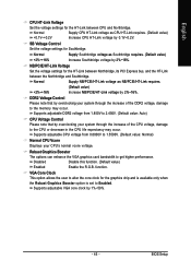
... the increase of the CPU voltage, damage to the memory may occur. Supports adjustable VGA core clock by 2%~16%. Disabled Disable this function. (Default value) Enabled Enable the R.G.B. function. SB Voltage Control Set the voltage settings for the HT-Link between Northbridge, its PCI Express bus, and the HT-Link between CPU and Northbridge. DDR2 Voltage Control Please note that by overclocking your CPU's normal vcore voltage. BIOS Setup English CPU HT-Link Voltage Set the voltage settings for the graphics chip and is available...
... the increase of the CPU voltage, damage to the memory may occur. Supports adjustable VGA core clock by 2%~16%. Disabled Disable this function. (Default value) Enabled Enable the R.G.B. function. SB Voltage Control Set the voltage settings for the HT-Link between Northbridge, its PCI Express bus, and the HT-Link between CPU and Northbridge. DDR2 Voltage Control Please note that by overclocking your CPU's normal vcore voltage. BIOS Setup English CPU HT-Link Voltage Set the voltage settings for the graphics chip and is available...
Manual
Page 47
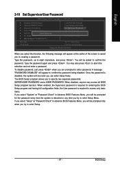
... Setup Type the password, up to abort the selection and not enter a password. English 2-10 Set Supervisor/User Password CMOS Setup Utility-Copyright (C) 1984-2006 Award Software ` Standard CMOS Features ` Advanced BIOS Features ` Integrated Peripherals ` Power Management Setup ` PnP/PCI ConfiguratioEnsnter Password: ` PC Health Status ` MB Intelligent Tweaker(M.I.T.) Load Fail-Safe Defaults Load Optimized Defaults Set Supervisor Password Set User Password Save & Exit Setup Exit Without Saving Esc: Quit F8: Q-Flash KLJI: Select Item F10: Save & Exit Setup Change/Set/Disable Password...
... Setup Type the password, up to abort the selection and not enter a password. English 2-10 Set Supervisor/User Password CMOS Setup Utility-Copyright (C) 1984-2006 Award Software ` Standard CMOS Features ` Advanced BIOS Features ` Integrated Peripherals ` Power Management Setup ` PnP/PCI ConfiguratioEnsnter Password: ` PC Health Status ` MB Intelligent Tweaker(M.I.T.) Load Fail-Safe Defaults Load Optimized Defaults Set Supervisor Password Set User Password Save & Exit Setup Exit Without Saving Esc: Quit F8: Q-Flash KLJI: Select Item F10: Save & Exit Setup Change/Set/Disable Password...
Manual
Page 54
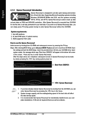
... press F9 during system power-on PATA and SATA IDE controllers. System requirements: 1. Save the settings and exit the BIOS Setup. If you have already entered Xpress Recovery2 by booting from the CD-ROM, you complete installations of OS and all required drivers as well as software. GA-M55plus-S3G (rev. 3.0) Motherboard - 54 - At least 64M bytes of the hard disk will affect the data backup speed. 3. After the steps...
... press F9 during system power-on PATA and SATA IDE controllers. System requirements: 1. Save the settings and exit the BIOS Setup. If you have already entered Xpress Recovery2 by booting from the CD-ROM, you complete installations of OS and all required drivers as well as software. GA-M55plus-S3G (rev. 3.0) Motherboard - 54 - At least 64M bytes of the hard disk will affect the data backup speed. 3. After the steps...
Manual
Page 57
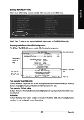
... From Main Bios Auto Recovery Enable Halt On Error Disable Copy Main ROM Data to Backup Load Default Settings Save Settings to CMOS Q-Flash Utility Load Main BIOS from Floppy Load Backup BIOS from Floppy Save Main BIOS to Floppy Save Backup BIOS to enter the Dual BIOS/Q-Flash utility. Step 2: Press F8 button on your keyboard and then Y button to Floppy Enter : Run :Move ESC:Reset F10:Power Off Dual BIOS utility bar Q-FlashTM utility title bar Action bar Task menu for Q-Flash utility: Contains the names of the task. English Entering the Q-FlashTM utility: Step1: To use Q-Flash...
... From Main Bios Auto Recovery Enable Halt On Error Disable Copy Main ROM Data to Backup Load Default Settings Save Settings to CMOS Q-Flash Utility Load Main BIOS from Floppy Load Backup BIOS from Floppy Save Main BIOS to Floppy Save Backup BIOS to enter the Dual BIOS/Q-Flash utility. Step 2: Press F8 button on your keyboard and then Y button to Floppy Enter : Run :Move ESC:Reset F10:Power Off Dual BIOS utility bar Q-FlashTM utility title bar Action bar Task menu for Q-Flash utility: Contains the names of the task. English Entering the Q-FlashTM utility: Step1: To use Q-Flash...
Manual
Page 60
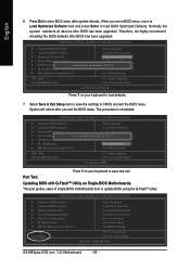
... after BIOS has been upgraded. This part guides users of single-BIOS motherboards how to CMOS and exit the BIOS menu. Normally the system redetects all devices after you are in BIOS menu, move to Load Optimized Defaults item and press Enter to save the settings to update BIOS using the Q-FlashTM utility. Select Save & Exit Setup item to save and exit. GA-M55plus-S3G (rev. 3.0) Motherboard - 60 - Part Two: Updating BIOS with Q-FlashTM Utility on your keyboard to load BIOS Optimized Defaults. English...
... after BIOS has been upgraded. This part guides users of single-BIOS motherboards how to CMOS and exit the BIOS menu. Normally the system redetects all devices after you are in BIOS menu, move to Load Optimized Defaults item and press Enter to save the settings to update BIOS using the Q-FlashTM utility. Select Save & Exit Setup item to save and exit. GA-M55plus-S3G (rev. 3.0) Motherboard - 60 - Part Two: Updating BIOS with Q-FlashTM Utility on your keyboard to load BIOS Optimized Defaults. English...

Manual
Page 71
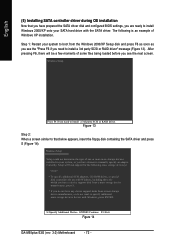
... startup disk. Boot from the menu. Press ENTER after each command (Figure 10): cd bootdrv menu Step 2: When the controller menu (Figure 11) appears, remove the startup disk and insert the blank formatted disk. Press 0 to a floppy disk. Figure 10 Figure 11 (Note) For users without a startup disk: Use an alternative system and insert the GIGABYTE motherboard driver CD-ROM. Without the driver, the hard disk may not be recognized during OS installation...
... startup disk. Boot from the menu. Press ENTER after each command (Figure 10): cd bootdrv menu Step 2: When the controller menu (Figure 11) appears, remove the startup disk and insert the blank formatted disk. Press 0 to a floppy disk. Figure 10 Figure 11 (Note) For users without a startup disk: Use an alternative system and insert the GIGABYTE motherboard driver CD-ROM. Without the driver, the hard disk may not be recognized during OS installation...
Manual
Page 72
... not want to install Windows 2000/XP onto your SATA hard drive with Windows, press ENTER. S=Specify Additional Device ENTER=Continue F3=Exit Figure 14 GA-M55plus-S3G (rev. 3.0) Motherboard - 72 - The following mass storage devices(s) * To specify additional SCSI adapters, CD-ROM drives, or special disk controllers for use with Windows, including those for use with the SATA driver. Figure 13 Step 2: When a screen similar to that you have prepared the SATA driver disk and configured BIOS settings, you are...
... not want to install Windows 2000/XP onto your SATA hard drive with Windows, press ENTER. S=Specify Additional Device ENTER=Continue F3=Exit Figure 14 GA-M55plus-S3G (rev. 3.0) Motherboard - 72 - The following mass storage devices(s) * To specify additional SCSI adapters, CD-ROM drives, or special disk controllers for use with Windows, including those for use with the SATA driver. Figure 13 Step 2: When a screen similar to that you have prepared the SATA driver disk and configured BIOS settings, you are...
Manual
Page 74
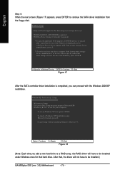
... Setup. To set up Windows XP now, press ENTER. After that hard drive. English Step 4: When the next screen (Figure 17) appears, press ENTER to be installed under Windows once for that , the driver will load support for the following mass storage device(s): NVIDIA RAID CLASS DRIVER (required) NVIDIA nForce Storage Controller (required) * To specify additional SCSI adapters, CD-ROM drives, or special disk controllers for which you have a device support disk from the floppy disk. To repair a Windows XP installation using Recovery...
... Setup. To set up Windows XP now, press ENTER. After that hard drive. English Step 4: When the next screen (Figure 17) appears, press ENTER to be installed under Windows once for that , the driver will load support for the following mass storage device(s): NVIDIA RAID CLASS DRIVER (required) NVIDIA nForce Storage Controller (required) * To specify additional SCSI adapters, CD-ROM drives, or special disk controllers for which you have a device support disk from the floppy disk. To repair a Windows XP installation using Recovery...
Manual
Page 80
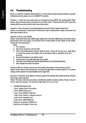
...may help you will be able to the Clear CMOS steps in the manual. Turn off the on-board battery to leak voltage to case. Why? Connect power cord to the battery holder. 5. AWARD BIOS Beep Codes 1 short: System boots successfully 2 short: CMOS setting error 1 long 1 short: DRAM or M/B error 1 long 2 short: Monitor or display card error 1 long 3 short: Keyboard error 1 long 9 short: BIOS ROM error Continuous long beeps: DRAM error Continuous short beeps: Power error GA-M55plus-S3G (rev. 3.0) Motherboard - 80 - If your board has a Clear CMOS jumper, please refer to see some...
...may help you will be able to the Clear CMOS steps in the manual. Turn off the on-board battery to leak voltage to case. Why? Connect power cord to the battery holder. 5. AWARD BIOS Beep Codes 1 short: System boots successfully 2 short: CMOS setting error 1 long 1 short: DRAM or M/B error 1 long 2 short: Monitor or display card error 1 long 3 short: Keyboard error 1 long 9 short: BIOS ROM error Continuous long beeps: DRAM error Continuous short beeps: Power error GA-M55plus-S3G (rev. 3.0) Motherboard - 80 - If your board has a Clear CMOS jumper, please refer to see some...


