Manual
Page 10
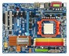
...® nForce 550 LAN Š Marvell 88E1116 phy (10/100/1000 Mbit) Audio Š Onboard Realtek ALC888 CODEC chip Š Supports High Definition Audio Š Supports 2 / 4 / 6 / 8 channel audio Š Supports S/PDIF In/Out connection Š Supports CD In connection IEEE 1394 Š Onboard T.I. English 1-2 Feature Summary CPU Š Socket AM2 for additional 2 ports by cables Š 1 Chassis Intrusion connector Š 1 power LED connector GA-M55S-S3 (rev. 2.0) Motherboard - 10 - ing connection of 2 IDE devices - 4 SATA 3Gb/s connectors (SATAII1, SATAII2, SATAII3...
...® nForce 550 LAN Š Marvell 88E1116 phy (10/100/1000 Mbit) Audio Š Onboard Realtek ALC888 CODEC chip Š Supports High Definition Audio Š Supports 2 / 4 / 6 / 8 channel audio Š Supports S/PDIF In/Out connection Š Supports CD In connection IEEE 1394 Š Onboard T.I. English 1-2 Feature Summary CPU Š Socket AM2 for additional 2 ports by cables Š 1 Chassis Intrusion connector Š 1 power LED connector GA-M55S-S3 (rev. 2.0) Motherboard - 10 - ing connection of 2 IDE devices - 4 SATA 3Gb/s connectors (SATAII1, SATAII2, SATAII3...
Manual
Page 11
...serial port (COMA) Š 4 USB 2.0/1.1 ports Š 1 IEEE 1394a port Š 1 RJ-45 port Š 6 audio jacks (Line In / Line Out / MIC In / Surround Speaker Out (Rear Speaker Out) / Center/Subwoofer Speaker Out / Side Speaker Out) I/O Control Š IT8716 chip Hardware Monitor Š System voltage detection Š CPU temperature detection Š CPU / Power / System fan speed detection Š CPU warning temperature Š CPU / Power / System fan failure warning Š Supports CPU Smart Fan function(Note 2) BIOS Š 1 4Mbit flash ROM Š Use of licensed AWARD BIOS...
...serial port (COMA) Š 4 USB 2.0/1.1 ports Š 1 IEEE 1394a port Š 1 RJ-45 port Š 6 audio jacks (Line In / Line Out / MIC In / Surround Speaker Out (Rear Speaker Out) / Center/Subwoofer Speaker Out / Side Speaker Out) I/O Control Š IT8716 chip Hardware Monitor Š System voltage detection Š CPU temperature detection Š CPU / Power / System fan speed detection Š CPU warning temperature Š CPU / Power / System fan failure warning Š Supports CPU Smart Fan function(Note 2) BIOS Š 1 4Mbit flash ROM Š Use of licensed AWARD BIOS...
Manual
Page 18
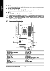
... audio software. In addition to the default speakers settings, the ~ audio jacks can be reconfigured to Line Out (Front Speaker Out) jack. Only microphones still MUST be connected to the 2-/4-/6-/8- Line Out (Front Speaker Out) The default Line Out (Front Speaker Out) jack. channel audio setup steps for detailed software configuration information. 1-7 Connectors Introduction 3 14 6 2 8 13 15 14 7 1) ATX_12V 2) ATX (Power Connector) 3) PCIE_12V 4) CPU_FAN 5) SYS_FAN 6) PWR_FAN 7) FDD 8) IDE1 9) SATAII1 / 2 / 3 / 4 10) BATTERY GA-M55S-S3...
... audio software. In addition to the default speakers settings, the ~ audio jacks can be reconfigured to Line Out (Front Speaker Out) jack. Only microphones still MUST be connected to the 2-/4-/6-/8- Line Out (Front Speaker Out) The default Line Out (Front Speaker Out) jack. channel audio setup steps for detailed software configuration information. 1-7 Connectors Introduction 3 14 6 2 8 13 15 14 7 1) ATX_12V 2) ATX (Power Connector) 3) PCIE_12V 4) CPU_FAN 5) SYS_FAN 6) PWR_FAN 7) FDD 8) IDE1 9) SATAII1 / 2 / 3 / 4 10) BATTERY GA-M55S-S3...
Manual
Page 20
... GA-M55S-S3 (rev. 2.0) Motherboard - 20 - The black connector wire is the ground wire (GND). Connect this connector depending on your system requirements. 1 PIin No. Remember to connect the CPU/system/power fan cable to the CPU_FAN/SYS_FAN/PWR_FAN connector to the PCIE x16 slot. Definition 1 NC 2 GND 3 GND 4 +12V 4/5/6) CPU_FAN / SYS_FAN / PWR_FAN (Cooler Fan Power Connector) The cooler fan power connector supplies a +12V power voltage via a 3-pin/4-pin (only for CPU_FAN) power connector and possesses a foolproof connection design. English 3) PCIE_12V (Power Connector...
... GA-M55S-S3 (rev. 2.0) Motherboard - 20 - The black connector wire is the ground wire (GND). Connect this connector depending on your system requirements. 1 PIin No. Remember to connect the CPU/system/power fan cable to the CPU_FAN/SYS_FAN/PWR_FAN connector to the PCIE x16 slot. Definition 1 NC 2 GND 3 GND 4 +12V 4/5/6) CPU_FAN / SYS_FAN / PWR_FAN (Cooler Fan Power Connector) The cooler fan power connector supplies a +12V power voltage via a 3-pin/4-pin (only for CPU_FAN) power connector and possesses a foolproof connection design. English 3) PCIE_12V (Power Connector...

Manual
Page 21
... IDE devices, please set the jumper on one IDE cable, and the single IDE cable can connect to one IDE device as Master and the other end of FDD drives supported are: 360KB, 720KB, 1.2MB, 1.44MB and 2.88MB. Hardware Installation English 7) FDD (FDD Connector) The FDD connector is used to connect the FDD cable while the other as Slave (for information on settings, please refer to the instructions located on the IDE device). The types...
... IDE devices, please set the jumper on one IDE cable, and the single IDE cable can connect to one IDE device as Master and the other end of FDD drives supported are: 360KB, 720KB, 1.2MB, 1.44MB and 2.88MB. Hardware Installation English 7) FDD (FDD Connector) The FDD connector is used to connect the FDD cable while the other as Slave (for information on settings, please refer to the instructions located on the IDE device). The types...
Manual
Page 22
...-install the battery. 4. Please refer to work properly. Plug the power cord in order to the BIOS setting for the SATA 3Gb/s and install the proper driver in and turn on the computer. If you can provide up to erase CMOS... 1. SATAII4 Pin No. Dispose of explosion if battery is incorrectly replaced. Replace only with the same or equivalent type recommended by nForce 550) SATA 3Gb/s can use a metal...
...-install the battery. 4. Please refer to work properly. Plug the power cord in order to the BIOS setting for the SATA 3Gb/s and install the proper driver in and turn on the computer. If you can provide up to erase CMOS... 1. SATAII4 Pin No. Dispose of explosion if battery is incorrectly replaced. Replace only with the same or equivalent type recommended by nForce 550) SATA 3Gb/s can use a metal...

Manual
Page 23
... LED/Power/Sleep LED) (Yellow) PW (Power Switch) (Red) SPEAK (Speaker Connector) (Amber) HD (IDE Hard Disk Active LED) (Blue) RES (Reset Switch) (Green) NC ( Purple) Pin 1: LED anode(+) Pin 2: LED cathode(-) Open: Normal Close: Power On/Off Pin 1: Power Pin 2- Hardware Installation of your chassis front panel to the F_PANEL connector according to the pin assignment below. PW+ PWSPEAK+ SPEAK- 2 20 1 19 HD+ HD- Pin 3: NC Pin 4: Data(-) Pin 1: LED anode(+) Pin 2: LED cathode(-) Open: Normal Close: Reset Hardware System NC - 23 - Message LED/ Power/ Sleep LED Power Switch Speaker...
... LED/Power/Sleep LED) (Yellow) PW (Power Switch) (Red) SPEAK (Speaker Connector) (Amber) HD (IDE Hard Disk Active LED) (Blue) RES (Reset Switch) (Green) NC ( Purple) Pin 1: LED anode(+) Pin 2: LED cathode(-) Open: Normal Close: Power On/Off Pin 1: Power Pin 2- Hardware Installation of your chassis front panel to the F_PANEL connector according to the pin assignment below. PW+ PWSPEAK+ SPEAK- 2 20 1 19 HD+ HD- Pin 3: NC Pin 4: Data(-) Pin 1: LED anode(+) Pin 2: LED cathode(-) Open: Normal Close: Reset Hardware System NC - 23 - Message LED/ Power/ Sleep LED Power Switch Speaker...
Manual
Page 24
...'97 Audio: Pin No. GA-M55S-S3 (rev. 2.0) Motherboard - 24 - Pin No. If you connect the front panel audio module. Check the pin assignments carefully while you wish to use the front audio function, connect the front panel audio module to this connector, please refer to the instructions on /off. Incorrect connection between the module and connector will blink when the system enters suspend mode(S1). It will make the audio device unable to work...
...'97 Audio: Pin No. GA-M55S-S3 (rev. 2.0) Motherboard - 24 - Pin No. If you connect the front panel audio module. Check the pin assignments carefully while you wish to use the front audio function, connect the front panel audio module to this connector, please refer to the instructions on /off. Incorrect connection between the module and connector will blink when the system enters suspend mode(S1). It will make the audio device unable to work...
Manual
Page 30
... a profile. English : For Boot Menu Select boot sequence for your system becomes unstable and you load the default BIOS settings, you want, press "Ctrl+F1" to access advanced options. 2. M55S-S3 FAa . . . . :BIOS Setup/Q-Flash, : XpressRecovery2, : Boot Menu 09/28/2006-NV-MCP55S-6A61JG07C-00 Press F12 Boot Menu == Select a Boot First device == Floppy LS120 Hard Disk CDROM ZIP USB-FDD USB-ZIP USB-CDROM USB-HDD Legacy LAN :Move Enter:Accept ESC:Exit Press to enter the Boot Menu and use this function to...
... a profile. English : For Boot Menu Select boot sequence for your system becomes unstable and you load the default BIOS settings, you want, press "Ctrl+F1" to access advanced options. 2. M55S-S3 FAa . . . . :BIOS Setup/Q-Flash, : XpressRecovery2, : Boot Menu 09/28/2006-NV-MCP55S-6A61JG07C-00 Press F12 Boot Menu == Select a Boot First device == Floppy LS120 Hard Disk CDROM ZIP USB-FDD USB-ZIP USB-CDROM USB-HDD Legacy LAN :Move Enter:Accept ESC:Exit Press to enter the Boot Menu and use this function to...

Manual
Page 32
... IDE HDD Auto-Detection Press "Enter" to automatically detect IDE/SATA devices during POST(default) None Select this option for faster system start up . English 2-1 Standard CMOS Features Date (mm:dd:yy) Time (hh:mm:ss) CMOS Setup Utility-Copyright (C) 1984-2006 Award Software Standard CMOS Features Mon, Oct 30 2006 9:45:15 Item Help Menu Level IDE Channel 0 Master IDE Channel 0 Slave IDE Channel 2 Master IDE Channel 3 Master IDE Channel 4 Master IDE Channel 5 Master [None] [None] [None] [None] [None] [None] Drive A Drive B Floppy 3 Mode Support...
... IDE HDD Auto-Detection Press "Enter" to automatically detect IDE/SATA devices during POST(default) None Select this option for faster system start up . English 2-1 Standard CMOS Features Date (mm:dd:yy) Time (hh:mm:ss) CMOS Setup Utility-Copyright (C) 1984-2006 Award Software Standard CMOS Features Mon, Oct 30 2006 9:45:15 Item Help Menu Level IDE Channel 0 Master IDE Channel 0 Slave IDE Channel 2 Master IDE Channel 3 Master IDE Channel 4 Master IDE Channel 5 Master [None] [None] [None] [None] [None] [None] Drive A Drive B Floppy 3 Mode Support...

Manual
Page 40
...) GA-M55S-S3 (rev. 2.0) Motherboard - 40 - to S3/STR(Suspend To RAM). Disabled Enabled Disable this function. (Default value) Enable USB device wake up event.(Default value) Modem Ring On An incoming call via modem can set "Power-On by Alarm" item to Enabled and key in Date/Time to POWER ON system. Day of Month Alarm x Time (hh:mm:ss) Alarm Power On By Mouse Power On By Keyboard x KB Power ON Password AC...
...) GA-M55S-S3 (rev. 2.0) Motherboard - 40 - to S3/STR(Suspend To RAM). Disabled Enabled Disable this function. (Default value) Enable USB device wake up event.(Default value) Modem Ring On An incoming call via modem can set "Power-On by Alarm" item to Enabled and key in Date/Time to POWER ON system. Day of Month Alarm x Time (hh:mm:ss) Alarm Power On By Mouse Power On By Keyboard x KB Power ON Password AC...

Manual
Page 48
... confirm the password being disabled. GA-M55S-S3 (rev. 2.0) Motherboard - 48 - If you select "Setup" at "Password Check" in Advance BIOS Features Menu, you will be prompted for entering the BIOS Setup program and having full configuration fields, the User password is rebooted or any time you try to enter Setup. English 2-10 Set Supervisor/User Password CMOS Setup Utility-Copyright (C) 1984-2006 Award Software Standard CMOS Features Advanced BIOS Features Integrated Peripherals Power Management Setup PnP/PCI ConfiguratioEnsnter Password: PC Health...
... confirm the password being disabled. GA-M55S-S3 (rev. 2.0) Motherboard - 48 - If you select "Setup" at "Password Check" in Advance BIOS Features Menu, you will be prompted for entering the BIOS Setup program and having full configuration fields, the User password is rebooted or any time you try to enter Setup. English 2-10 Set Supervisor/User Password CMOS Setup Utility-Copyright (C) 1984-2006 Award Software Standard CMOS Features Advanced BIOS Features Integrated Peripherals Power Management Setup PnP/PCI ConfiguratioEnsnter Password: PC Health...

Manual
Page 56
... F9 during system power-on PATA and SATA IDE controllers. M55S-S3 FAa . . . . :BIOS Setup/Q-Flash, : XpressRecovery2, : Boot Menu 09/28/2006-NV-MCP55S-6A61JG07C-00 Boot from the CD-ROM, you complete installations of system memory 3. If you can enter Xpress Recovery2 by pressing the key in your CD-ROM drive. GA-M55S-S3 (rev. 2.0) Motherboard - 56 - Press any key to boot from CD/DVD:" will affect the data backup speed. 3. Boot from CD-ROM for the first...
... F9 during system power-on PATA and SATA IDE controllers. M55S-S3 FAa . . . . :BIOS Setup/Q-Flash, : XpressRecovery2, : Boot Menu 09/28/2006-NV-MCP55S-6A61JG07C-00 Boot from the CD-ROM, you complete installations of system memory 3. If you can enter Xpress Recovery2 by pressing the key in your CD-ROM drive. GA-M55S-S3 (rev. 2.0) Motherboard - 56 - Press any key to boot from CD/DVD:" will affect the data backup speed. 3. Boot from CD-ROM for the first...
Manual
Page 59
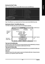
...the following key components. Appendix CMOS Setup Utility-Copyright (C) 1984-2004 Award Software Standard CMOS Features Advanced BIOS Features Integrated Peripherals Power Management Setup PnP/PCI Configurations PC Health Status MB Intelligent Tweaker(M.I.T.) ESC: Quit F8: Dual BIOS/Q-Flash Select Language Load Fail-Safe Defaults Load Optimized Defaults Set Supervisor Password Set User Password Save & Exit Setup Exit Without Saving F3: Change Language F10: Save & Exit Setup Time, Date, Hard Disk Type... Blocking a task and pressing Enter key on your keyboards to enter BIOS menu. Action...
...the following key components. Appendix CMOS Setup Utility-Copyright (C) 1984-2004 Award Software Standard CMOS Features Advanced BIOS Features Integrated Peripherals Power Management Setup PnP/PCI Configurations PC Health Status MB Intelligent Tweaker(M.I.T.) ESC: Quit F8: Dual BIOS/Q-Flash Select Language Load Fail-Safe Defaults Load Optimized Defaults Set Supervisor Password Set User Password Save & Exit Setup Exit Without Saving F3: Change Language F10: Save & Exit Setup Time, Date, Hard Disk Type... Blocking a task and pressing Enter key on your keyboards to enter BIOS menu. Action...

Manual
Page 62
...Save Data to CMOS Press Y on your keyboard to CMOS and exit the BIOS menu. When you exit the BIOS menu. Select Save & Exit Setup item to enter BIOS menu after BIOS has been upgraded. This part guides users of single-BIOS motherboards how to load BIOS Optimized Defaults. CMOS Setup Utility-Copyright (C) 1984-2004 Award Software Standard CMOS Features Select Language Advanced BIOS Features Load Fail-Safe Defaults Integrated Peripherals Load Optimized Defaults Power Management Setup Set Supervisor Password PnP/PCI Configurations Load Optimized Defaults (SYet/NU)s?eYr...
...Save Data to CMOS Press Y on your keyboard to CMOS and exit the BIOS menu. When you exit the BIOS menu. Select Save & Exit Setup item to enter BIOS menu after BIOS has been upgraded. This part guides users of single-BIOS motherboards how to load BIOS Optimized Defaults. CMOS Setup Utility-Copyright (C) 1984-2004 Award Software Standard CMOS Features Select Language Advanced BIOS Features Load Fail-Safe Defaults Integrated Peripherals Load Optimized Defaults Power Management Setup Set Supervisor Password PnP/PCI Configurations Load Optimized Defaults (SYet/NU)s?eYr...

Manual
Page 68
... system BIOS Setup and set BIOS boot sequence for the SATA hard drive(s)/RAID array. GA-M55S-S3 (rev. 2.0) Motherboard - 68 - CMOS Setup Utility-Copyright (C) 1984-2006 Award Software Integrated Peripherals Serial-ATA RAID Config On-Chip IDE Channel0 On-Chip MAC Lan NV Serial-ATA Controller IDE Prefetch Moed Onboard Audio Function SMART LAN Onboard 1394 Onboard LAN Boot ROM Onboard Serial Port 1 Onboard Parallel Port Parallel Port Mode x ECP Mode Use DMA On-Chip USB USB Keyboard Support USB Mouse Support Legacy USB storage detect [Press Enter] [Enabled] [Auto] [All Enabled] [Enabled] [Auto...
... system BIOS Setup and set BIOS boot sequence for the SATA hard drive(s)/RAID array. GA-M55S-S3 (rev. 2.0) Motherboard - 68 - CMOS Setup Utility-Copyright (C) 1984-2006 Award Software Integrated Peripherals Serial-ATA RAID Config On-Chip IDE Channel0 On-Chip MAC Lan NV Serial-ATA Controller IDE Prefetch Moed Onboard Audio Function SMART LAN Onboard 1394 Onboard LAN Boot ROM Onboard Serial Port 1 Onboard Parallel Port Parallel Port Mode x ECP Mode Use DMA On-Chip USB USB Keyboard Support USB Mouse Support Legacy USB storage detect [Press Enter] [Enabled] [Auto] [All Enabled] [Enabled] [Auto...

Manual
Page 73
..., remove the startup disk and insert the blank formatted disk. A command prompt window will then automatically zip and transfer this driver file to install the SATA controller driver during the Windows setup process. Appendix Prepare a startup disk that in MS-DOS mode(Note). Step 1: Insert the prepared startup disk and motherboard driver CD-ROM in the BootDrv folder (Figure 12). Figure 10 Figure 11 (Note) For users without a startup disk: Use...
..., remove the startup disk and insert the blank formatted disk. A command prompt window will then automatically zip and transfer this driver file to install the SATA controller driver during the Windows setup process. Appendix Prepare a startup disk that in MS-DOS mode(Note). Step 1: Insert the prepared startup disk and motherboard driver CD-ROM in the BootDrv folder (Figure 12). Figure 10 Figure 11 (Note) For users without a startup disk: Use...

Manual
Page 74
... Additional Device ENTER=Continue F3=Exit Figure 14 GA-M55S-S3 (rev. 2.0) Motherboard - 74 - After pressing F6, there will load support for use with Windows, including those for which you have a device support disk from a mass storage device manufacturer, press S. * If you see the next screen. Step 1: Restart your SATA hard drive with Windows, press ENTER. The following mass storage devices(s) * To specify additional SCSI adapters, CD-ROM drives, or special disk controllers for use with the SATA driver. English (5) Installing SATA controller driver...
... Additional Device ENTER=Continue F3=Exit Figure 14 GA-M55S-S3 (rev. 2.0) Motherboard - 74 - After pressing F6, there will load support for use with Windows, including those for which you have a device support disk from a mass storage device manufacturer, press S. * If you see the next screen. Step 1: Restart your SATA hard drive with Windows, press ENTER. The following mass storage devices(s) * To specify additional SCSI adapters, CD-ROM drives, or special disk controllers for use with the SATA driver. English (5) Installing SATA controller driver...

Manual
Page 76
.../XP installation. To repair a Windows XP installation using Recovery Console, press R. To quit Setup without installing Windows XP, press F3. Windows Setup Setup will load support for the following mass storage device(s): NVIDIA RAID CLASS DRIVER (required) NVIDIA NForce Storage Controller (required) * To specify additional SCSI adapters, CD-ROM drives, or special disk controllers for which you have a device support disk from a mass storage device manufacturer, press S. * If you do not want to be installed.) GA-M55S-S3 (rev. 2.0) Motherboard - 76 - S=Specify Additional Device ENTER...
.../XP installation. To repair a Windows XP installation using Recovery Console, press R. To quit Setup without installing Windows XP, press F3. Windows Setup Setup will load support for the following mass storage device(s): NVIDIA RAID CLASS DRIVER (required) NVIDIA NForce Storage Controller (required) * To specify additional SCSI adapters, CD-ROM drives, or special disk controllers for which you have a device support disk from a mass storage device manufacturer, press S. * If you do not want to be installed.) GA-M55S-S3 (rev. 2.0) Motherboard - 76 - S=Specify Additional Device ENTER...
Manual
Page 82
... board has a Clear CMOS jumper, please refer to the Clear CMOS steps in previous BIOS after system boots up the speaker to the maximum volume? Re-insert the battery to enter BIOS and load Fail-Safe Defaults(or load Optimized Defaults). 7. Question 3: How do these options. AWARD BIOS Beep Codes 1 short: System boots successfully 2 short: CMOS setting error 1 long 1 short: DRAM or M/B error 1 long 2 short: Monitor or display card error 1 long 3 short: Keyboard error 1 long 9 short: BIOS ROM error Continuous long beeps: DRAM error Continuous short beeps: Power error GA-M55S-S3 (rev...
... board has a Clear CMOS jumper, please refer to the Clear CMOS steps in previous BIOS after system boots up the speaker to the maximum volume? Re-insert the battery to enter BIOS and load Fail-Safe Defaults(or load Optimized Defaults). 7. Question 3: How do these options. AWARD BIOS Beep Codes 1 short: System boots successfully 2 short: CMOS setting error 1 long 1 short: DRAM or M/B error 1 long 2 short: Monitor or display card error 1 long 3 short: Keyboard error 1 long 9 short: BIOS ROM error Continuous long beeps: DRAM error Continuous short beeps: Power error GA-M55S-S3 (rev...


