Manual
Page 1
GA-M55S-S3 (rev. 2.0) AMD Socket AM2 Processor Motherboard User's Manual Rev. 2002 12ME-M55S3R-2002R * The WEEE marking on the product indicates this product must not be disposed of with user's other household waste and must be handed over to a designated collection point for the recycling of waste electrical and electronic equipment!! * The WEEE marking applies only in European Union's member states.
GA-M55S-S3 (rev. 2.0) AMD Socket AM2 Processor Motherboard User's Manual Rev. 2002 12ME-M55S3R-2002R * The WEEE marking on the product indicates this product must not be disposed of with user's other household waste and must be handed over to a designated collection point for the recycling of waste electrical and electronic equipment!! * The WEEE marking applies only in European Union's member states.
Manual
Page 2
Motherboard GA-M55S-S3 (rev. 2.0) Nov. 10, 2006 Motherboard GA-M55S-S3 (rev. 2.0) Nov. 10, 2006
Motherboard GA-M55S-S3 (rev. 2.0) Nov. 10, 2006 Motherboard GA-M55S-S3 (rev. 2.0) Nov. 10, 2006
Manual
Page 4
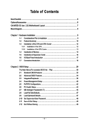
Table of Contents ItemChecklist ...6 OptionalAccessories ...6 GA-M55S-S3 (rev. 2.0) Motherboard Layout 7 Block Diagram ...8 Chapter 1 Hardware Installation 9 1-1 Considerations Prior to Installation 9 1-2 Feature Summary 10 1-3 Installation of the CPU and CPU Cooler 12 1-3-1 Installation of the CPU ...
Table of Contents ItemChecklist ...6 OptionalAccessories ...6 GA-M55S-S3 (rev. 2.0) Motherboard Layout 7 Block Diagram ...8 Chapter 1 Hardware Installation 9 1-1 Considerations Prior to Installation 9 1-2 Feature Summary 10 1-3 Installation of the CPU and CPU Cooler 12 1-3-1 Installation of the CPU ...
Manual
Page 7
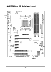
GA-M55S-S3 (rev. 2.0) Motherboard Layout CPU_FAN KB_MS ATX_12V ATX SPDIF_O SPDIFO_OPT Socket AM2 COMA LPT PWR_FAN USB 1394 USB LAN1 Marvell 88E1116 AUDIO PCIE_12V F_AUDIO PCIE_1 CODEC PCIE_16_1 PCIE_2 SPDIF_I CD_IN PCIE_3 PCIE_4 PCI1 IT8716 PCI2 REV: 2.0 FDD DDRII_1 DDRII_2 DDRII_3 DDRII_4 GA-M55S-S3 IDE1 SATAII4 SATAII1 SATAII2 SATAII3 BIOS nVIDIA® nForce 550 CLR_CMOS TSB43AB23 BATTERY F_USB3 F_USB2 F_USB1 F1_1394 F2_1394 CI F_PANEL PWR_LED SYS_FAN - 7 -
GA-M55S-S3 (rev. 2.0) Motherboard Layout CPU_FAN KB_MS ATX_12V ATX SPDIF_O SPDIFO_OPT Socket AM2 COMA LPT PWR_FAN USB 1394 USB LAN1 Marvell 88E1116 AUDIO PCIE_12V F_AUDIO PCIE_1 CODEC PCIE_16_1 PCIE_2 SPDIF_I CD_IN PCIE_3 PCIE_4 PCI1 IT8716 PCI2 REV: 2.0 FDD DDRII_1 DDRII_2 DDRII_3 DDRII_4 GA-M55S-S3 IDE1 SATAII4 SATAII1 SATAII2 SATAII3 BIOS nVIDIA® nForce 550 CLR_CMOS TSB43AB23 BATTERY F_USB3 F_USB2 F_USB1 F1_1394 F2_1394 CI F_PANEL PWR_LED SYS_FAN - 7 -

Manual
Page 9
...as physical harm to be an unofficial Gigabyte product. - 9 - Please turn off before unplugging the power supply connector from the motherboard. These stickers are uncertain about any installation steps or have these items on the motherboard or within a electrostatic shielding container. ... Installation 1-1 Considerations Prior to natural disaster, accident or human cause. 2. Damage due to Installation Preparing Your Computer The motherboard contains numerous delicate electronic circuits and components which can lead to damage to system components as well as a result of ...
...as physical harm to be an unofficial Gigabyte product. - 9 - Please turn off before unplugging the power supply connector from the motherboard. These stickers are uncertain about any installation steps or have these items on the motherboard or within a electrostatic shielding container. ... Installation 1-1 Considerations Prior to natural disaster, accident or human cause. 2. Damage due to Installation Preparing Your Computer The motherboard contains numerous delicate electronic circuits and components which can lead to damage to system components as well as a result of ...
Manual
Page 10
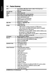
... connection of 4 SATA 3Gb/s devices - English 1-2 Feature Summary CPU Š Socket AM2 for additional 2 ports by cables Š 1 Chassis Intrusion connector Š 1 power LED connector GA-M55S-S3 (rev. 2.0) Motherboard - 10 - ing connection of 2 IDE devices - 4 SATA 3Gb/s connectors (SATAII1, SATAII2, SATAII3, SATAII4), allow-
... connection of 4 SATA 3Gb/s devices - English 1-2 Feature Summary CPU Š Socket AM2 for additional 2 ports by cables Š 1 Chassis Intrusion connector Š 1 power LED connector GA-M55S-S3 (rev. 2.0) Motherboard - 10 - ing connection of 2 IDE devices - 4 SATA 3Gb/s connectors (SATAII1, SATAII2, SATAII3, SATAII4), allow-
Manual
Page 11
... is installed, the actual memory available for the operating system will depend on the CPU you install. (Note 3) EasyTune functions may vary depending on different motherboards. - 11 - English Rear Panel I/O Š 1 PS/2 keyboard port Š 1 PS/2 mouse port Š 1 parallel port Š 1 S/PDIF out port (coaxial) Š 1 S/PDIF out port (optical...
... is installed, the actual memory available for the operating system will depend on the CPU you install. (Note 3) EasyTune functions may vary depending on different motherboards. - 11 - English Rear Panel I/O Š 1 PS/2 keyboard port Š 1 PS/2 mouse port Š 1 parallel port Š 1 S/PDIF out port (coaxial) Š 1 S/PDIF out port (optical...
Manual
Page 12
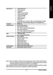
... as shown in accordance with the following conditions: 1. The pin 1 location is not recommended that corresponds to system use extra care when installing the CPU. GA-M55S-S3 (rev. 2.0) Motherboard - 12 - Fig.1 Socket Lever Position lever at a 90 degree angle. The CPU will not insert properly. Pin One Fig.2 Pin 1 location on the CPU...
... as shown in accordance with the following conditions: 1. The pin 1 location is not recommended that corresponds to system use extra care when installing the CPU. GA-M55S-S3 (rev. 2.0) Motherboard - 12 - Fig.1 Socket Lever Position lever at a 90 degree angle. The CPU will not insert properly. Pin One Fig.2 Pin 1 location on the CPU...

Manual
Page 13
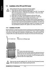
... cooler. - 13 - English 1-3-2 Installation of the CPU Cooler Fig.1 Before installing the CPU cooler, please first add an even layer of heat paste on the motherboard so that either thermal tape rather than heat paste be used for detailed installation instructions). To prevent such an occurrence, it is suggested that the...
... cooler. - 13 - English 1-3-2 Installation of the CPU Cooler Fig.1 Before installing the CPU cooler, please first add an even layer of heat paste on the motherboard so that either thermal tape rather than heat paste be used for detailed installation instructions). To prevent such an occurrence, it is suggested that the...

Manual
Page 14
.... Reverse the installation steps when you are designed so that memory of Memory Before installing the memory modules, please comply with each slot. GA-M55S-S3 (rev. 2.0) Motherboard - 14 - Then push it down. Insert the DIMM memory module vertically into the DIMM socket. English 1-4 Installation of similar capacity, ... the memory used . 2. Before installing or removing memory modules, please make sure that the computer power is supported by the motherboard. Memory modules are unable to lock the DIMM module. The memory capacity used can only fit in only one direction.
.... Reverse the installation steps when you are designed so that memory of Memory Before installing the memory modules, please comply with each slot. GA-M55S-S3 (rev. 2.0) Motherboard - 14 - Then push it down. Insert the DIMM memory module vertically into the DIMM socket. English 1-4 Installation of similar capacity, ... the memory used . 2. Before installing or removing memory modules, please make sure that the computer power is supported by the motherboard. Memory modules are unable to lock the DIMM module. The memory capacity used can only fit in only one direction.
Manual
Page 16
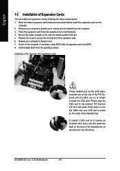
...'s instruction document before install the expansion card into expansion slot in the slot. 5. Be sure the metal contacts on the card are indeed seated in motherboard. 4. GA-M55S-S3 (rev. 2.0) Motherboard - 16 - Replace your computer's chassis cover, screws and slot bracket from the computer. 3. Install related driver from BIOS. 8. Please align the VGA card to...
...'s instruction document before install the expansion card into expansion slot in the slot. 5. Be sure the metal contacts on the card are indeed seated in motherboard. 4. GA-M55S-S3 (rev. 2.0) Motherboard - 16 - Replace your computer's chassis cover, screws and slot bracket from the computer. 3. Install related driver from BIOS. 8. Please align the VGA card to...
Manual
Page 18
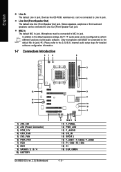
... for detailed software configuration information. 1-7 Connectors Introduction 3 14 6 2 8 13 15 14 7 1) ATX_12V 2) ATX (Power Connector) 3) PCIE_12V 4) CPU_FAN 5) SYS_FAN 6) PWR_FAN 7) FDD 8) IDE1 9) SATAII1 / 2 / 3 / 4 10) BATTERY GA-M55S-S3 (rev. 2.0) Motherboard 9 9 19 10 5 17 1812 11 16 11) F_PANEL 12) PWR_LED 13) F_AUDIO 14) CD_IN 15) SPDIF_I 16) F_USB1 / F_USB2 / F_USB3 17) F1_1394 / F2_1394 18) CI...
... for detailed software configuration information. 1-7 Connectors Introduction 3 14 6 2 8 13 15 14 7 1) ATX_12V 2) ATX (Power Connector) 3) PCIE_12V 4) CPU_FAN 5) SYS_FAN 6) PWR_FAN 7) FDD 8) IDE1 9) SATAII1 / 2 / 3 / 4 10) BATTERY GA-M55S-S3 (rev. 2.0) Motherboard 9 9 19 10 5 17 1812 11 16 11) F_PANEL 12) PWR_LED 13) F_AUDIO 14) CD_IN 15) SPDIF_I 16) F_USB1 / F_USB2 / F_USB3 17) F1_1394 / F2_1394 18) CI...
Manual
Page 19
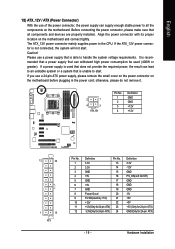
... please make sure that is recommended that a power supply that can lead to an unstable system or a system that all the components on the motherboard. The ATX_12V power connector mainly supplies power to the CPU. It is unable to start . Align the power connector with its proper location on ...the motherboard before plugging in the power cord; Please use a power supply that does not provide the required power, the result can withstand high power ...
... please make sure that is recommended that a power supply that can lead to an unstable system or a system that all the components on the motherboard. The ATX_12V power connector mainly supplies power to the CPU. It is unable to start . Align the power connector with its proper location on ...the motherboard before plugging in the power cord; Please use a power supply that does not provide the required power, the result can withstand high power ...
Manual
Page 20
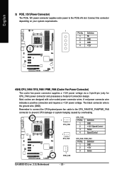
Definition 1 GND 2 +12V 3 Sense GA-M55S-S3 (rev. 2.0) Motherboard - 20 - Definition 1 NC 2 GND 3 GND 4 +12V 4/5/6) CPU_FAN / SYS_FAN / PWR_FAN (Cooler Fan Power Connector) The cooler fan power connector supplies a +12V power voltage via a 3-pin/4-pin (...
Definition 1 GND 2 +12V 3 Sense GA-M55S-S3 (rev. 2.0) Motherboard - 20 - Definition 1 NC 2 GND 3 GND 4 +12V 4/5/6) CPU_FAN / SYS_FAN / PWR_FAN (Cooler Fan Power Connector) The cooler fan power connector supplies a +12V power voltage via a 3-pin/4-pin (...
Manual
Page 22
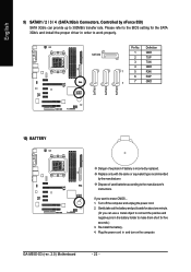
... unplug the power cord. 2. Plug the power cord in the battery holder to connect the positive and negative pins in and turn on the computer. GA-M55S-S3 (rev. 2.0) Motherboard - 22 - If you can provide up to work properly. Dispose of explosion if battery is incorrectly replaced. Please refer to the BIOS setting for...
... unplug the power cord. 2. Plug the power cord in the battery holder to connect the positive and negative pins in and turn on the computer. GA-M55S-S3 (rev. 2.0) Motherboard - 22 - If you can provide up to work properly. Dispose of explosion if battery is incorrectly replaced. Please refer to the BIOS setting for...
Manual
Page 24
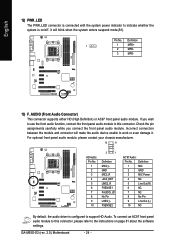
... this connector, please refer to the instructions on /off. Incorrect connection between the module and connector will blink when the system enters suspend mode(S1). GA-M55S-S3 (rev. 2.0) Motherboard - 24 - Definition 1 MIC 2 GND 3 MIC Power 4 NC 5 Line Out (R) 6 NC 7 NC 8 No Pin 9 Line Out (L) 10 NC By default, the audio driver is on...
... this connector, please refer to the instructions on /off. Incorrect connection between the module and connector will blink when the system enters suspend mode(S1). GA-M55S-S3 (rev. 2.0) Motherboard - 24 - Definition 1 MIC 2 GND 3 MIC Power 4 NC 5 Line Out (R) 6 NC 7 NC 8 No Pin 9 Line Out (L) 10 NC By default, the audio driver is on...
Manual
Page 26
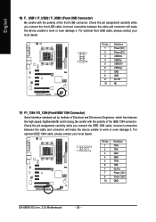
... features like high speed, highbandwidth and hot plug. Definition 2 10 1 9 1 TPA+ 2 TPA- 3 GND 4 GND 5 TPB+ 6 TPB- 7 No Pin 7 Power (12V) 8 Power (12V) 10 GND GA-M55S-S3 (rev. 2.0) Motherboard - 26 - For optional front USB cable, please contact your local dealer. Be careful with the polarity of the front USB connector. Check the pin assignment...
... features like high speed, highbandwidth and hot plug. Definition 2 10 1 9 1 TPA+ 2 TPA- 3 GND 4 GND 5 TPB+ 6 TPB- 7 No Pin 7 Power (12V) 8 Power (12V) 10 GND GA-M55S-S3 (rev. 2.0) Motherboard - 26 - For optional front USB cable, please contact your local dealer. Be careful with the polarity of the front USB connector. Check the pin assignment...

Manual
Page 28
English GA-M55S-S3 (rev. 2.0) Motherboard - 28 -
English GA-M55S-S3 (rev. 2.0) Motherboard - 28 -
Manual
Page 29
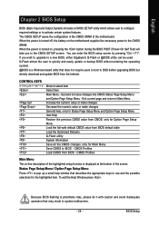
... Chapter 2 BIOS Setup BIOS (Basic Input and Output System) includes a CMOS SETUP utility which allows user to configure required settings or to a new BIOS, either Gigabyte's Q-Flash or @BIOS utility can enter the BIOS setup screen by pressing "Ctrl + F1". The CMOS SETUP saves the configuration in system malfunction. - 29 - ...Move to DOS before upgrading BIOS but directly download and update BIOS from the Internet. When the power is displayed at the bottom of the motherboard. CMOS Profiles Main Menu The on-line description of the highlighted setup function is turned on the...
... Chapter 2 BIOS Setup BIOS (Basic Input and Output System) includes a CMOS SETUP utility which allows user to configure required settings or to a new BIOS, either Gigabyte's Q-Flash or @BIOS utility can enter the BIOS setup screen by pressing "Ctrl + F1". The CMOS SETUP saves the configuration in system malfunction. - 29 - ...Move to DOS before upgrading BIOS but directly download and update BIOS from the Internet. When the power is displayed at the bottom of the motherboard. CMOS Profiles Main Menu The on-line description of the highlighted setup function is turned on the...
Manual
Page 30
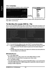
... select a device, then press enter to accept or enter the sub-menu. Use arrow keys to select among the items and press to accept. GA-M55S-S3 (rev. 2.0) Motherboard - 30 - M55S-S3 FAa . . . . :BIOS Setup/Q-Flash, : XpressRecovery2, : Boot Menu 09/28/2006-NV-MCP55S-6A61JG07C-00 Press F12 Boot Menu == Select a Boot First device == Floppy LS120...
... select a device, then press enter to accept or enter the sub-menu. Use arrow keys to select among the items and press to accept. GA-M55S-S3 (rev. 2.0) Motherboard - 30 - M55S-S3 FAa . . . . :BIOS Setup/Q-Flash, : XpressRecovery2, : Boot Menu 09/28/2006-NV-MCP55S-6A61JG07C-00 Press F12 Boot Menu == Select a Boot First device == Floppy LS120...


