Manual
Page 4
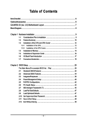
Table of Contents ItemChecklist ...6 OptionalAccessories ...6 GA-M55S-S3 (rev. 2.0) Motherboard Layout 7 Block Diagram ...8 Chapter 1 Hardware Installation 9 1-1 Considerations Prior to Installation 9 1-2 Feature Summary 10 1-3 Installation of ...14 1-5 Installation of Expansion Cards 16 1-6 I/O Back Panel Introduction 17 1-7 Connectors Introduction 18 Chapter 2 BIOS Setup 29 The Main Menu (For example: BIOS Ver. : FAa 30 2-1 Standard CMOS Features 32 2-2 Advanced BIOS Features 34 2-3 IntegratedPeripherals 36 2-4 Power Management Setup 40 2-5 PnP/PCI Configurations 42 2-6 PC Health ...
Table of Contents ItemChecklist ...6 OptionalAccessories ...6 GA-M55S-S3 (rev. 2.0) Motherboard Layout 7 Block Diagram ...8 Chapter 1 Hardware Installation 9 1-1 Considerations Prior to Installation 9 1-2 Feature Summary 10 1-3 Installation of ...14 1-5 Installation of Expansion Cards 16 1-6 I/O Back Panel Introduction 17 1-7 Connectors Introduction 18 Chapter 2 BIOS Setup 29 The Main Menu (For example: BIOS Ver. : FAa 30 2-1 Standard CMOS Features 32 2-2 Advanced BIOS Features 34 2-3 IntegratedPeripherals 36 2-4 Power Management Setup 40 2-5 PnP/PCI Configurations 42 2-6 PC Health ...

Manual
Page 5
Chapter 3 Drivers Installation 51 3-1 Install Chipset Drivers 51 3-2 SoftwareApplications 52 3-3 Driver CD Information 52 3-4 Hardware Information 53 3-5 Contact Us ...53 Chapter 4 Appendix 55 4-1 Unique Software Utilities 55 4-1-1 EasyTune 5 Introduction 55 4-1-2 Xpress Recovery2 Introduction 56 4-1-3 Flash BIOS Method Introduction 58 4-1-4 Configuring SATA Hard Drive(s 67 4-1-5 2- / 4- / 6- / 8- Channel Audio Function Introduction 77 4-2 Troubleshooting 82 - 5 -
Chapter 3 Drivers Installation 51 3-1 Install Chipset Drivers 51 3-2 SoftwareApplications 52 3-3 Driver CD Information 52 3-4 Hardware Information 53 3-5 Contact Us ...53 Chapter 4 Appendix 55 4-1 Unique Software Utilities 55 4-1-1 EasyTune 5 Introduction 55 4-1-2 Xpress Recovery2 Introduction 56 4-1-3 Flash BIOS Method Introduction 58 4-1-4 Configuring SATA Hard Drive(s 67 4-1-5 2- / 4- / 6- / 8- Channel Audio Function Introduction 77 4-2 Troubleshooting 82 - 5 -
Manual
Page 7
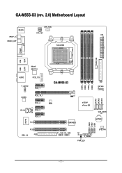
GA-M55S-S3 (rev. 2.0) Motherboard Layout CPU_FAN KB_MS ATX_12V ATX SPDIF_O SPDIFO_OPT Socket AM2 COMA LPT PWR_FAN USB 1394 USB LAN1 Marvell 88E1116 AUDIO PCIE_12V F_AUDIO PCIE_1 CODEC PCIE_16_1 PCIE_2 SPDIF_I CD_IN PCIE_3 PCIE_4 PCI1 IT8716 PCI2 REV: 2.0 FDD DDRII_1 DDRII_2 DDRII_3 DDRII_4 GA-M55S-S3 IDE1 SATAII4 SATAII1 SATAII2 SATAII3 BIOS nVIDIA® nForce 550 CLR_CMOS TSB43AB23 BATTERY F_USB3 F_USB2 F_USB1 F1_1394 F2_1394 CI F_PANEL PWR_LED SYS_FAN - 7 -
GA-M55S-S3 (rev. 2.0) Motherboard Layout CPU_FAN KB_MS ATX_12V ATX SPDIF_O SPDIFO_OPT Socket AM2 COMA LPT PWR_FAN USB 1394 USB LAN1 Marvell 88E1116 AUDIO PCIE_12V F_AUDIO PCIE_1 CODEC PCIE_16_1 PCIE_2 SPDIF_I CD_IN PCIE_3 PCIE_4 PCI1 IT8716 PCI2 REV: 2.0 FDD DDRII_1 DDRII_2 DDRII_3 DDRII_4 GA-M55S-S3 IDE1 SATAII4 SATAII1 SATAII2 SATAII3 BIOS nVIDIA® nForce 550 CLR_CMOS TSB43AB23 BATTERY F_USB3 F_USB2 F_USB1 F1_1394 F2_1394 CI F_PANEL PWR_LED SYS_FAN - 7 -

Manual
Page 8
Block Diagram PCI-ECLK (100 MHz) AMD Socket AM2 CPU CPUCLK+/-(200 MHz) DDRII 800/667/533 MHz DIMM Hyper Transport Bus Dual Channel Memory LAN PCI Express x16 PCI-ECLK (100 MHz) PCI Express Bus x1 x1 x1 x1 nVIDIA® nForce 550 4 PCI Express x1 PCI Bus TSB43AB23 CODEC RJ45 Marvell 88E1116 BIOS 4 SATA 3Gb/s ATA33/66/100/133 IDE Channel LPC BUS IT8716 Floppy LPT Port COM Port 3 IEEE 1394a 10 USB Ports PS/2 KB/Mouse 2 PCI Surround Speaker Out Center/Subwoofer Speaker Out Side Speaker Out MIC Line-Out Line-In SPDIF In SPDIF Out - 8 -
Block Diagram PCI-ECLK (100 MHz) AMD Socket AM2 CPU CPUCLK+/-(200 MHz) DDRII 800/667/533 MHz DIMM Hyper Transport Bus Dual Channel Memory LAN PCI Express x16 PCI-ECLK (100 MHz) PCI Express Bus x1 x1 x1 x1 nVIDIA® nForce 550 4 PCI Express x1 PCI Bus TSB43AB23 CODEC RJ45 Marvell 88E1116 BIOS 4 SATA 3Gb/s ATA33/66/100/133 IDE Channel LPC BUS IT8716 Floppy LPT Port COM Port 3 IEEE 1394a 10 USB Ports PS/2 KB/Mouse 2 PCI Surround Speaker Out Center/Subwoofer Speaker Out Side Speaker Out MIC Line-Out Line-In SPDIF In SPDIF Out - 8 -
Manual
Page 11
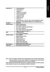
... Š CPU / Power / System fan failure warning Š Supports CPU Smart Fan function(Note 2) BIOS Š 1 4Mbit flash ROM Š Use of licensed AWARD BIOS Additional Features Š Supports @BIOS Š Supports Download Center Š Supports Q-Flash Š Supports EasyTune(Note 3) Š Supports Xpress... Install Š Supports Xpress Recovery2 Š Supports Xpress BIOS Rescue Bundle Software Š Norton Internet Security (OEM version) Form Factor Š ATX form factor; 30.5cm x 23.4cm (...
... Š CPU / Power / System fan failure warning Š Supports CPU Smart Fan function(Note 2) BIOS Š 1 4Mbit flash ROM Š Use of licensed AWARD BIOS Additional Features Š Supports @BIOS Š Supports Download Center Š Supports Q-Flash Š Supports EasyTune(Note 3) Š Supports Xpress... Install Š Supports Xpress Recovery2 Š Supports Xpress BIOS Rescue Bundle Software Š Norton Internet Security (OEM version) Form Factor Š ATX form factor; 30.5cm x 23.4cm (...

Manual
Page 14
... one direction. Then push it down. Insert the DIMM memory module vertically into the DIMM socket. Memory modules have a foolproof insertion design. GA-M55S-S3 (rev. 2.0) Motherboard - 14 - A memory module can be inserted only in one direction. If you wish to prevent hardware damage. ... when you are designed so that the computer power is supported by the motherboard. The motherboard supports DDRII memory modules, whereby BIOS will automatically detect memory capacity and specifications. Fig.2 Close the plastic clip at both edges of the DIMM sockets to insert ...
... one direction. Then push it down. Insert the DIMM memory module vertically into the DIMM socket. Memory modules have a foolproof insertion design. GA-M55S-S3 (rev. 2.0) Motherboard - 14 - A memory module can be inserted only in one direction. If you wish to prevent hardware damage. ... when you are designed so that the computer power is supported by the motherboard. The motherboard supports DDRII memory modules, whereby BIOS will automatically detect memory capacity and specifications. Fig.2 Close the plastic clip at both edges of the DIMM sockets to insert ...
Manual
Page 16
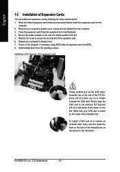
...Replace your computer's chassis cover, screws and slot bracket from the operating system. Power on the computer, if necessary, setup BIOS utility of the expansion card. 6. Installing a PCI Express x16 expansion card: Please carefully pull out the small whitedrawable bar...slot. 5. Press the expansion card firmly into the computer. 2. Replace the screw to secure the slot bracket of expansion card from BIOS. 8. Install related driver from the computer. 3. GA-M55S-S3 (rev. 2.0) Motherboard - 16 - Be sure the metal contacts on the card are indeed seated in motherboard. 4. To install...
...Replace your computer's chassis cover, screws and slot bracket from the operating system. Power on the computer, if necessary, setup BIOS utility of the expansion card. 6. Installing a PCI Express x16 expansion card: Please carefully pull out the small whitedrawable bar...slot. 5. Press the expansion card firmly into the computer. 2. Replace the screw to secure the slot bracket of expansion card from BIOS. 8. Install related driver from the computer. 3. GA-M55S-S3 (rev. 2.0) Motherboard - 16 - Be sure the metal contacts on the card are indeed seated in motherboard. 4. To install...
Manual
Page 22
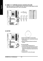
... SATAII3 9) SATAII1 / 2 / 3 / 4 (SATA 3Gb/s Connectors, Controlled by the manufacturer. Dispose of explosion if battery is incorrectly replaced. GA-M55S-S3 (rev. 2.0) Motherboard - 22 - Please refer to work properly. Plug the power cord in order to the BIOS setting for the SATA 3Gb/s and install the proper driver in and turn on the computer. Re...
... SATAII3 9) SATAII1 / 2 / 3 / 4 (SATA 3Gb/s Connectors, Controlled by the manufacturer. Dispose of explosion if battery is incorrectly replaced. GA-M55S-S3 (rev. 2.0) Motherboard - 22 - Please refer to work properly. Plug the power cord in order to the BIOS setting for the SATA 3Gb/s and install the proper driver in and turn on the computer. Re...
Manual
Page 27
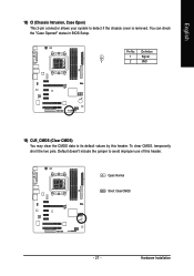
To clear CMOS, temporarily short the two pins. Pin No. You can check the "Case Opened" status in BIOS Setup. Default doesn't include the jumper to detect if the chassis cover is removed. Open: Normal Short: Clear CMOS - 27 - Hardware Installation English 18) CI (Chassis Intrusion, Case Open) This 2-pin connector allows your system to avoid improper use of this header. Definition 1 Signal 1 2 GND 19) CLR_CMOS (Clear CMOS) You may clear the CMOS data to its default values by this header.
To clear CMOS, temporarily short the two pins. Pin No. You can check the "Case Opened" status in BIOS Setup. Default doesn't include the jumper to detect if the chassis cover is removed. Open: Normal Short: Clear CMOS - 27 - Hardware Installation English 18) CI (Chassis Intrusion, Case Open) This 2-pin connector allows your system to avoid improper use of this header. Definition 1 Signal 1 2 GND 19) CLR_CMOS (Clear CMOS) You may clear the CMOS data to its default values by this header.
Manual
Page 29
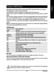
... Menu Item Help Restore the previous CMOS value from CMOS, only for Main Menu Save CMOS to a new BIOS, either Gigabyte's Q-Flash or @BIOS utility can enter the BIOS setup screen by pressing "Ctrl + F1". Because BIOS flashing is displayed at the bottom of the motherboard. To exit the Help Window press . Exit current page...
... Menu Item Help Restore the previous CMOS value from CMOS, only for Main Menu Save CMOS to a new BIOS, either Gigabyte's Q-Flash or @BIOS utility can enter the BIOS setup screen by pressing "Ctrl + F1". Because BIOS flashing is displayed at the bottom of the motherboard. To exit the Help Window press . Exit current page...
Manual
Page 30
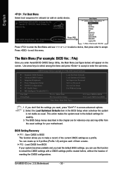
... < > to select a device, then press enter to the default settings for onboard (or add-on the screen. GA-M55S-S3 (rev. 2.0) Motherboard - 30 - CMOS Setup Utility-Copyright (C) 1984-2006 Award Software Standard CMOS Features Advanced BIOS Features Integrated Peripherals Power Management Setup PnP/PCI Configurations PC Health Status MB Intelligent Tweaker(M.I.T.) Load Fail-Safe...
... < > to select a device, then press enter to the default settings for onboard (or add-on the screen. GA-M55S-S3 (rev. 2.0) Motherboard - 30 - CMOS Setup Utility-Copyright (C) 1984-2006 Award Software Standard CMOS Features Advanced BIOS Features Integrated Peripherals Power Management Setup PnP/PCI Configurations PC Health Status MB Intelligent Tweaker(M.I.T.) Load Fail-Safe...

Manual
Page 31
... „ Standard CMOS Features This setup page includes all the items in standard compatible BIOS. „ Advanced BIOS Features This setup page includes all the items of Award special enhanced features. „ Integrated Peripherals This setup page includes all onboard peripherals. „ Power ...
... „ Standard CMOS Features This setup page includes all the items in standard compatible BIOS. „ Advanced BIOS Features This setup page includes all the items of Award special enhanced features. „ Integrated Peripherals This setup page includes all onboard peripherals. „ Power ...

Manual
Page 32
...this to set the access mode for the hard drive. Extended IDE Drive You can use one of three methods: Auto Allows BIOS to select this if no IDE/SATA devices are used and the system will skip the automatic detection step and allow for ... automatically detect IDE/SATA devices during POST. (Default value) None Select this option for automatic device detection. You can manually input the correct settings. GA-M55S-S3 (rev. 2.0) Motherboard - 32 - For example, 1 p.m. Access Mode Use this option for automatic device detection. is calculated based on the 24...
...this to set the access mode for the hard drive. Extended IDE Drive You can use one of three methods: Auto Allows BIOS to select this if no IDE/SATA devices are used and the system will skip the automatic detection step and allow for ... automatically detect IDE/SATA devices during POST. (Default value) None Select this option for automatic device detection. You can manually input the correct settings. GA-M55S-S3 (rev. 2.0) Motherboard - 32 - For example, 1 p.m. Access Mode Use this option for automatic device detection. is calculated based on the 24...

Manual
Page 33
... determine the amount of currently installed hard drive. Memory The category is display-only which is present during power up. Extended Memory The BIOS determines how much extended memory is determined by POST (Power On Self Test) of memory located above 1 MB in the system. None...drive; 360K byte capacity. 5.25 inch AT-type high-density drive; 1.2M byte capacity. (3.5 inch when 3 Mode is the amount of the BIOS. Cylinder Number of cylinders Head Precomp Landing Zone Number of heads Write precomp Landing zone Sector Number of sectors Drive A / Drive B The category ...
... determine the amount of currently installed hard drive. Memory The category is display-only which is present during power up. Extended Memory The BIOS determines how much extended memory is determined by POST (Power On Self Test) of memory located above 1 MB in the system. None...drive; 360K byte capacity. 5.25 inch AT-type high-density drive; 1.2M byte capacity. (3.5 inch when 3 Mode is the amount of the BIOS. Cylinder Number of cylinders Head Precomp Landing Zone Number of heads Write precomp Landing zone Sector Number of sectors Drive A / Drive B The category ...

Manual
Page 34
... F1: General Help F7: Optimized Defaults Hard Disk Boot Priority Select boot sequence for floppy disk drive to determine it is 360K. (Default value) GA-M55S-S3 (rev. 2.0) Motherboard - 34 - Select your boot device priority by ZIP. CDROM Select your boot device priority by Legacy LAN. Disabled Disable this... menu. ZIP Select your boot device priority by USB-FDD. USB-HDD Select your boot device priority by CDROM. Note that BIOS can not tell from 720K, 1.2M or 1.44M drive type as they are all 80 tracks. Use < > or < > to select a ...
... F1: General Help F7: Optimized Defaults Hard Disk Boot Priority Select boot sequence for floppy disk drive to determine it is 360K. (Default value) GA-M55S-S3 (rev. 2.0) Motherboard - 34 - Select your boot device priority by ZIP. CDROM Select your boot device priority by Legacy LAN. Disabled Disable this... menu. ZIP Select your boot device priority by USB-FDD. USB-HDD Select your boot device priority by CDROM. Note that BIOS can not tell from 720K, 1.2M or 1.44M drive type as they are all 80 tracks. Use < > or < > to select a ...

Manual
Page 35
... in a low-power mode that appears off.) Init Display First This feature allows you install a PCI card and a PCI Express VGA card on the motherboard. BIOS Setup PCI Slot PEG Set Init Display First to select the first initiation of the monitor display from which card when you to PCI VGA...
... in a low-power mode that appears off.) Init Display First This feature allows you install a PCI card and a PCI Express VGA card on the motherboard. BIOS Setup PCI Slot PEG Set Init Display First to select the first initiation of the monitor display from which card when you to PCI VGA...

Manual
Page 37
... cable: - 37 - Onboard Audio Function Auto Auto-detect onboard audio function. (Default value) Disabled Disable this channel. Refer to detect the status of this function. BIOS Setup English NV SATA 2 Secondary RAID Enabled Enable RAID function for the second channel of the second SATA controller. (Default value) Disabled Disable the RAID...
... cable: - 37 - Onboard Audio Function Auto Auto-detect onboard audio function. (Default value) Disabled Disable this channel. Refer to detect the status of this function. BIOS Setup English NV SATA 2 Secondary RAID Enabled Enable RAID function for the second channel of the second SATA controller. (Default value) Disabled Disable the RAID...

Manual
Page 38
.../IRQ5 Enable onboard LPT port and address is 278/IRQ5. 3BC/IRQ7 Enable onboard LPT port and address is attached to the fault or short. GA-M55S-S3 (rev. 2.0) Motherboard - 38 - If no cable problem is the approximate length of Pair 1-2, Pair 3-6, Pair 4-5, and Pair 7-8 will show ...of wires will show 0.0m. If no cable problem is 2E8/IRQ3. Enabled Enable this function. (Default value) Onboard Serial Port 1 Auto BIOS will show N/A. ECP Using Parallel port as Enhanced Parallel Port. Onboard 1394 Enabled Enable onboard IEEE 1394 function. (Default value) Disabled Disable ...
.../IRQ5 Enable onboard LPT port and address is 278/IRQ5. 3BC/IRQ7 Enable onboard LPT port and address is attached to the fault or short. GA-M55S-S3 (rev. 2.0) Motherboard - 38 - If no cable problem is the approximate length of Pair 1-2, Pair 3-6, Pair 4-5, and Pair 7-8 will show ...of wires will show 0.0m. If no cable problem is 2E8/IRQ3. Enabled Enable this function. (Default value) Onboard Serial Port 1 Auto BIOS will show N/A. ECP Using Parallel port as Enhanced Parallel Port. Onboard 1394 Enabled Enable onboard IEEE 1394 function. (Default value) Disabled Disable ...

Manual
Page 39
... detect This option allows users to decide whether to 1. Disabled Disable USB keyboard support. (Default value) USB Mouse Support Enabled Enable USB mouse support. BIOS Setup Enabled BIOS will become available when Parallel Port Mode set to ECP or ECP+EPP. 3 Set ECP Mode Use DMA to 3. (Default value) 1 Set ECP Mode...
... detect This option allows users to decide whether to 1. Disabled Disable USB keyboard support. (Default value) USB Mouse Support Enabled Enable USB mouse support. BIOS Setup Enabled BIOS will become available when Parallel Port Mode set to ECP or ECP+EPP. 3 Set ECP Mode Use DMA to 3. (Default value) 1 Set ECP Mode...

Manual
Page 41
... here. Power On By Keyboard Disabled Disable this function. (Default value) Double-Click Double click on PS/2 mouse left button to power on the system. BIOS Setup English Power On By Mouse Disabled Disable this function. (Default value) Password Enter from 1 to 5 characters) and press Enter to set the Keyboard Power...
... here. Power On By Keyboard Disabled Disable this function. (Default value) Double-Click Double click on PS/2 mouse left button to power on the system. BIOS Setup English Power On By Mouse Disabled Disable this function. (Default value) Password Enter from 1 to 5 characters) and press Enter to set the Keyboard Power...


