Manual
Page 4
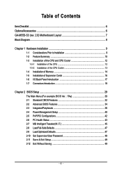
Table of Contents ItemChecklist ...6 OptionalAccessories ...6 GA-M55S-S3 (rev. 2.0) Motherboard Layout 7 Block Diagram ...8 Chapter 1 Hardware Installation 9 1-1 Considerations Prior to Installation 9 1-2 Feature Summary 10 1-3 Installation of the CPU and CPU Cooler 12 1-3-1 Installation of the CPU 12 1-3-2 Installation of the CPU Cooler 13 1-4 Installation of Memory 14 1-5 Installation of Expansion Cards 16 1-6 I/O Back Panel Introduction 17 1-7 Connectors Introduction 18...
Table of Contents ItemChecklist ...6 OptionalAccessories ...6 GA-M55S-S3 (rev. 2.0) Motherboard Layout 7 Block Diagram ...8 Chapter 1 Hardware Installation 9 1-1 Considerations Prior to Installation 9 1-2 Feature Summary 10 1-3 Installation of the CPU and CPU Cooler 12 1-3-1 Installation of the CPU 12 1-3-2 Installation of the CPU Cooler 13 1-4 Installation of Memory 14 1-5 Installation of Expansion Cards 16 1-6 I/O Back Panel Introduction 17 1-7 Connectors Introduction 18...

Manual
Page 8
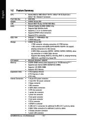
Block Diagram PCI-ECLK (100 MHz) AMD Socket AM2 CPU CPUCLK+/-(200 MHz) DDRII 800/667/533 MHz DIMM Hyper Transport Bus Dual Channel Memory LAN PCI Express x16 PCI-ECLK (100 MHz) PCI Express Bus x1 x1 x1 x1 nVIDIA® nForce 550 4 PCI Express x1 PCI Bus TSB43AB23 CODEC RJ45 Marvell 88E1116 BIOS 4 SATA 3Gb/s ATA33/66/100/133 IDE Channel LPC BUS IT8716 Floppy LPT Port COM Port 3 IEEE 1394a 10 USB Ports PS/2 KB/Mouse 2 PCI Surround Speaker Out Center/Subwoofer Speaker Out Side Speaker Out MIC Line-Out Line-In SPDIF In SPDIF Out - 8 -
Block Diagram PCI-ECLK (100 MHz) AMD Socket AM2 CPU CPUCLK+/-(200 MHz) DDRII 800/667/533 MHz DIMM Hyper Transport Bus Dual Channel Memory LAN PCI Express x16 PCI-ECLK (100 MHz) PCI Express Bus x1 x1 x1 x1 nVIDIA® nForce 550 4 PCI Express x1 PCI Bus TSB43AB23 CODEC RJ45 Marvell 88E1116 BIOS 4 SATA 3Gb/s ATA33/66/100/133 IDE Channel LPC BUS IT8716 Floppy LPT Port COM Port 3 IEEE 1394a 10 USB Ports PS/2 KB/Mouse 2 PCI Surround Speaker Out Center/Subwoofer Speaker Out Side Speaker Out MIC Line-Out Line-In SPDIF In SPDIF Out - 8 -

Manual
Page 9
...uncertain about any installation steps or have these items on an uneven surface. 7. If you are connected. 4. Damage due to be an unofficial Gigabyte product. - 9 - Product determined to natural disaster, accident or human cause. 2. Thus, prior to the installation of the motherboard or any ...using the product, please verify that the power supply is best to wear an electrostatic discharge (ESD) cuff when handling electronic components (CPU, RAM). 4. Damage due to use of uncertified components. 5. To prevent damage to the motherboard, please do not remove the stickers ...
...uncertain about any installation steps or have these items on an uneven surface. 7. If you are connected. 4. Damage due to be an unofficial Gigabyte product. - 9 - Product determined to natural disaster, accident or human cause. 2. Thus, prior to the installation of the motherboard or any ...using the product, please verify that the power supply is best to wear an electrostatic discharge (ESD) cuff when handling electronic components (CPU, RAM). 4. Damage due to use of uncertified components. 5. To prevent damage to the motherboard, please do not remove the stickers ...
Manual
Page 10
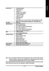
... ATX power connector Š 1 4-pin ATX 12V power connector Š 1 floppy connector Š 1 IDE connector Š 4 SATA 3Gb/s connectors Š 1 CPU fan connector Š 1 system fan connector Š 1 power fan connector Š 1 front panel connector Š 1 front audio connector Š 1 CD In ...ATA 66/ATA 100/ATA 133 support, allowing connection of 4 SATA 3Gb/s devices - English 1-2 Feature Summary CPU Š Socket AM2 for additional 2 ports by cables Š 1 Chassis Intrusion connector Š 1 power LED connector GA-M55S-S3 (rev. 2.0) Motherboard - 10 -
... ATX power connector Š 1 4-pin ATX 12V power connector Š 1 floppy connector Š 1 IDE connector Š 4 SATA 3Gb/s connectors Š 1 CPU fan connector Š 1 system fan connector Š 1 power fan connector Š 1 front panel connector Š 1 front audio connector Š 1 CD In ...ATA 66/ATA 100/ATA 133 support, allowing connection of 4 SATA 3Gb/s devices - English 1-2 Feature Summary CPU Š Socket AM2 for additional 2 ports by cables Š 1 Chassis Intrusion connector Š 1 power LED connector GA-M55S-S3 (rev. 2.0) Motherboard - 10 -
Manual
Page 11
...will be less than 4 GB of physical memory is installed, the actual memory available for the operating system will depend on the CPU you install. (Note 3) EasyTune functions may vary depending on different motherboards. - 11 - Hardware Installation English Rear Panel I/O Š...Š IT8716 chip Hardware Monitor Š System voltage detection Š CPU temperature detection Š CPU / Power / System fan speed detection Š CPU warning temperature Š CPU / Power / System fan failure warning Š Supports CPU Smart Fan function(Note 2) BIOS Š 1 4Mbit flash ROM &#...
...will be less than 4 GB of physical memory is installed, the actual memory available for the operating system will depend on the CPU you install. (Note 3) EasyTune functions may vary depending on different motherboards. - 11 - Hardware Installation English Rear Panel I/O Š...Š IT8716 chip Hardware Monitor Š System voltage detection Š CPU temperature detection Š CPU / Power / System fan speed detection Š CPU warning temperature Š CPU / Power / System fan failure warning Š Supports CPU Smart Fan function(Note 2) BIOS Š 1 4Mbit flash ROM &#...
Manual
Page 12
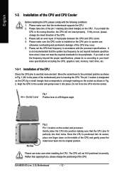
... beyond the proper specifications, please do so according to your hardware specifications including the CPU, graphics card, memory, hard drive, etc. 1-3-1 Installation of the CPU Check the CPU pins to inserting the CPU. Move the socket lever to the unlocked position as shown in accordance with the following... finger down on the socket as shown in the wrong direction, the CPU will not fit if positioned incorrectly. Pin One Fig.2 Pin 1 location on the CPU. GA-M55S-S3 (rev. 2.0) Motherboard - 12 - Align the CPU to the socket and gently lower it does not meet the required standards...
... beyond the proper specifications, please do so according to your hardware specifications including the CPU, graphics card, memory, hard drive, etc. 1-3-1 Installation of the CPU Check the CPU pins to inserting the CPU. Move the socket lever to the unlocked position as shown in accordance with the following... finger down on the socket as shown in the wrong direction, the CPU will not fit if positioned incorrectly. Pin One Fig.2 Pin 1 location on the CPU. GA-M55S-S3 (rev. 2.0) Motherboard - 12 - Align the CPU to the socket and gently lower it does not meet the required standards...

Manual
Page 13
... for heat dissipation or using extreme care when removing the CPU cooler. - 13 - Fig.2 Please connect the CPU cooler power connector to prevent CPU overheating. To prevent such an occurrence, it is suggested that the CPU cooler can properly function to the CPU_FAN connector located on ...the surface of the CPU. Hardware Installation Install all the CPU cooler components (Please refer to the CPU as a result of hardening of the heat paste. English 1-3-2 Installation of the CPU Cooler Fig.1 Before installing the CPU cooler, please first add an even layer...
... for heat dissipation or using extreme care when removing the CPU cooler. - 13 - Fig.2 Please connect the CPU cooler power connector to prevent CPU overheating. To prevent such an occurrence, it is suggested that the CPU cooler can properly function to the CPU_FAN connector located on ...the surface of the CPU. Hardware Installation Install all the CPU cooler components (Please refer to the CPU as a result of hardening of the heat paste. English 1-3-2 Installation of the CPU Cooler Fig.1 Before installing the CPU cooler, please first add an even layer...
Manual
Page 15
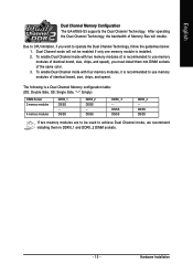
...modules of identical brand, size, chips, and speed), you wish to use memory modules of the same color. 3. English Dual Channel Memory Configuration The GA-M55S-S3 supports the Dual Channel Technology. DS/SS DDRII_ 3 - Due to be enabled if only one memory module is a Dual Channel Memory configuration table: (... DDRII_1 DS/SS - Dual Channel mode will double. The following is installed. 2. DS/SS DS/SS If two memory modules are to CPU limitation, if you must install them in DDRII_1 and DDRII_2 DIMM sockets. - 15 - DS/SS DDRII_2 DS/SS - Hardware Installation
...modules of identical brand, size, chips, and speed), you wish to use memory modules of the same color. 3. English Dual Channel Memory Configuration The GA-M55S-S3 supports the Dual Channel Technology. DS/SS DDRII_ 3 - Due to be enabled if only one memory module is a Dual Channel Memory configuration table: (... DDRII_1 DS/SS - Dual Channel mode will double. The following is installed. 2. DS/SS DS/SS If two memory modules are to CPU limitation, if you must install them in DDRII_1 and DDRII_2 DIMM sockets. - 15 - DS/SS DDRII_2 DS/SS - Hardware Installation
Manual
Page 19
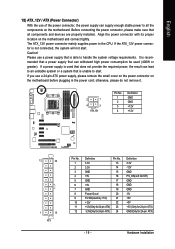
... mainly supplies power to start . If the ATX_12V power connector is able to all components and devices are properly installed. It is unable to the CPU. English 1/2) ATX_12V / ATX (Power Connector) With the use a 24-pin ATX power supply, please remove the small cover on the power connector on the motherboard...
... mainly supplies power to start . If the ATX_12V power connector is able to all components and devices are properly installed. It is unable to the CPU. English 1/2) ATX_12V / ATX (Power Connector) With the use a 24-pin ATX power supply, please remove the small cover on the power connector on the motherboard...
Manual
Page 20
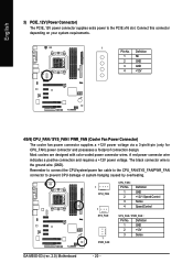
A red power connector wire indicates a positive connection and requires a +12V power voltage. Definition 1 GND 2 +12V 3 Sense GA-M55S-S3 (rev. 2.0) Motherboard - 20 - Definition 1 NC 2 GND 3 GND 4 +12V 4/5/6) CPU_FAN / SYS_FAN / PWR_FAN (Cooler Fan Power Connector) ...GND). Most coolers are designed with color-coded power connector wires. English 3) PCIE_12V (Power Connector) The PCIE_12V power connector supplies extra power to prevent CPU damage or system hanging caused by overheating. 1 CPU_FAN 1 SYS_FAN 1 PWR_FAN CPU_FAN : Pin No. 1 2 3 4 Definition GND +12V /...
A red power connector wire indicates a positive connection and requires a +12V power voltage. Definition 1 GND 2 +12V 3 Sense GA-M55S-S3 (rev. 2.0) Motherboard - 20 - Definition 1 NC 2 GND 3 GND 4 +12V 4/5/6) CPU_FAN / SYS_FAN / PWR_FAN (Cooler Fan Power Connector) ...GND). Most coolers are designed with color-coded power connector wires. English 3) PCIE_12V (Power Connector) The PCIE_12V power connector supplies extra power to prevent CPU damage or system hanging caused by overheating. 1 CPU_FAN 1 SYS_FAN 1 PWR_FAN CPU_FAN : Pin No. 1 2 3 4 Definition GND +12V /...

Manual
Page 31
BIOS Setup It allows you to limit access to the system and Setup, or just to control CPU clock and frequency ratio. „ Load Fail-Safe Defaults Fail-Safe Defaults indicates the value of the system parameters which the system would be in ...
BIOS Setup It allows you to limit access to the system and Setup, or just to control CPU clock and frequency ratio. „ Load Fail-Safe Defaults Fail-Safe Defaults indicates the value of the system parameters which the system would be in ...

Manual
Page 33
... of heads Write precomp Landing zone Sector Number of sectors Drive A / Drive B The category identifies the types of base (or conventional) memory installed in the CPU's memory address map. - 33 - Floppy 3 Mode Support (for a disk error; it will stop for a keyboard or disk error; it will not stop for all other...
... of heads Write precomp Landing zone Sector Number of sectors Drive A / Drive B The category identifies the types of base (or conventional) memory installed in the CPU's memory address map. - 33 - Floppy 3 Mode Support (for a disk error; it will stop for a keyboard or disk error; it will not stop for all other...

Manual
Page 43
... Reset Case Open Status Case Opened Vcore DDR18V +3.3V +12V Current CPU Temperature Current CPU FAN Speed Current POWER FAN Speed Current SYSTEM FAN Speed CPU Warning Temperature CPU FAN Fail Warning POWER FAN Fail Warning SYSTEM FAN Fail Warning CPU Smart FAN Control (Note) CPU Smart FAN Mode [Disabled] Yes OK OK OK OK 45oC...
... Reset Case Open Status Case Opened Vcore DDR18V +3.3V +12V Current CPU Temperature Current CPU FAN Speed Current POWER FAN Speed Current SYSTEM FAN Speed CPU Warning Temperature CPU FAN Fail Warning POWER FAN Fail Warning SYSTEM FAN Fail Warning CPU Smart FAN Control (Note) CPU Smart FAN Mode [Disabled] Yes OK OK OK OK 45oC...

Manual
Page 44
...PWM Set to Voltage when you install. GA-M55S-S3 (rev. 2.0) Motherboard - 44 - Enabled When this function. Users can adjust the fan speed with a 3-pin fan power cable. Auto BIOS autodetects the type of CPU fan you installed and sets the optimal CPU Smart FAN control mode for it. (...at different speed depending on the CPU you use a CPU fan with Easy Tune based on their requirements. (Default value) CPU Smart FAN Mode This option is available only when CPU Smart FAN Control is enabled, CPU fan will depend on CPU temperature. English CPU Smart FAN Control (Note) Disabled...
...PWM Set to Voltage when you install. GA-M55S-S3 (rev. 2.0) Motherboard - 44 - Enabled When this function. Users can adjust the fan speed with a 3-pin fan power cable. Auto BIOS autodetects the type of CPU fan you installed and sets the optimal CPU Smart FAN control mode for it. (...at different speed depending on the CPU you use a CPU fan with Easy Tune based on their requirements. (Default value) CPU Smart FAN Mode This option is available only when CPU Smart FAN Control is enabled, CPU fan will depend on CPU temperature. English CPU Smart FAN Control (Note) Disabled...

Manual
Page 45
...This setup option will not show up if the CPU ratio is not changeable. DDR2 Voltage Control Please note that the M.I .T.) CPU Frequency (MHz) PCIE Clock (MHz) CPU Clock Ratio DDR2 Voltage Control Chipset/PCIE Voltage HT-Link Voltage CPU HT-Link Voltage CPU Voltage Control Normal CPU Vcore [Auto] [Auto] [Auto] [Normal] ... as Chipset/PCIE requires. (Default value) +0.025V ~ +0.375V Increase Chipset/PCIE voltage by 0.025V~0.700V. Doing a overclock or overvoltage on CPU, chipsets and memory modules may occur. The option will display "Locked" and read only or will automatically assign by...
...This setup option will not show up if the CPU ratio is not changeable. DDR2 Voltage Control Please note that the M.I .T.) CPU Frequency (MHz) PCIE Clock (MHz) CPU Clock Ratio DDR2 Voltage Control Chipset/PCIE Voltage HT-Link Voltage CPU HT-Link Voltage CPU Voltage Control Normal CPU Vcore [Auto] [Auto] [Auto] [Normal] ... as Chipset/PCIE requires. (Default value) +0.025V ~ +0.375V Increase Chipset/PCIE voltage by 0.025V~0.700V. Doing a overclock or overvoltage on CPU, chipsets and memory modules may occur. The option will display "Locked" and read only or will automatically assign by...

Manual
Page 46
... from 0.8000V to 1.5500V. (Default value: Normal) Normal CPU Vcore Display your system through the increase of the CPU voltage, damage to the CPU or decrease in the CPU life expectancy may occur. GA-M55S-S3 (rev. 2.0) Motherboard - 46 - CPU Voltage Control Please note that by 0.025V~0.375V. English CPU HT-Link Voltage Set the voltage settings for the...
... from 0.8000V to 1.5500V. (Default value: Normal) Normal CPU Vcore Display your system through the increase of the CPU voltage, damage to the CPU or decrease in the CPU life expectancy may occur. GA-M55S-S3 (rev. 2.0) Motherboard - 46 - CPU Voltage Control Please note that by 0.025V~0.375V. English CPU HT-Link Voltage Set the voltage settings for the...

Manual
Page 55
... Description Enters the Overclocking setting page Enters the C.I.A./2 and M.I .B. GO 6. GIGABYTE Logo 10. setting page Enters the Smart-Fan setting page Enters the PC Health setting page Confirmation and Execution button Toggles between Easy and Advance Mode Display panel of both CPU cooling fan and North-Bridge Chipset cooling fan, 4) PC health...
... Description Enters the Overclocking setting page Enters the C.I.A./2 and M.I .B. GO 6. GIGABYTE Logo 10. setting page Enters the Smart-Fan setting page Enters the PC Health setting page Confirmation and Execution button Toggles between Easy and Advance Mode Display panel of both CPU cooling fan and North-Bridge Chipset cooling fan, 4) PC health...


