
Manual
Page 3
...&Downloads\Motherboard\Technology Guide page on your motherboard revision before updating motherboard BIOS, drivers, or when looking for technical information. For product-related information, check on our website at: http://www.gigabyte.com Identifying Your Motherboard Revision The revision number on our website. The... trademarks mentioned in this : "REV: X.X." Changes to use of this product, GIGABYTE provides the following types of documentations: For quick set-up of the motherboard is the property of this manual are legally registered...
...&Downloads\Motherboard\Technology Guide page on your motherboard revision before updating motherboard BIOS, drivers, or when looking for technical information. For product-related information, check on our website at: http://www.gigabyte.com Identifying Your Motherboard Revision The revision number on our website. The... trademarks mentioned in this : "REV: X.X." Changes to use of this product, GIGABYTE provides the following types of documentations: For quick set-up of the motherboard is the property of this manual are legally registered...

Manual
Page 4
Table of Contents Box Contents...6 Optional Items...6 GA-M52LT-D3/GA-M52LT-S3P Motherboard Layout 7 GA-M52LT-D3/GA-M52LT-S3P Motherboard Block Diagram 8 Chapter 1 Hardware Installation 9 1-1 Installation Precautions 9 1-2 Product Specifications 10 1-3 Installing the CPU...an Expansion Card 17 1-6 Back Panel Connectors 18 1-7 Internal Connectors 20 Chapter 2 BIOS Setup 29 2-1 Startup Screen 30 2-2 The Main Menu 31 2-3 MB Intelligent Tweaker(M.I.T 33 2-4 Standard CMOS Features 36 2-5 Advanced BIOS Features 38 2-6 Integrated Peripherals 40 2-7 Power Management Setup 42 2-8 PnP/PCI ...
Table of Contents Box Contents...6 Optional Items...6 GA-M52LT-D3/GA-M52LT-S3P Motherboard Layout 7 GA-M52LT-D3/GA-M52LT-S3P Motherboard Block Diagram 8 Chapter 1 Hardware Installation 9 1-1 Installation Precautions 9 1-2 Product Specifications 10 1-3 Installing the CPU...an Expansion Card 17 1-6 Back Panel Connectors 18 1-7 Internal Connectors 20 Chapter 2 BIOS Setup 29 2-1 Startup Screen 30 2-2 The Main Menu 31 2-3 MB Intelligent Tweaker(M.I.T 33 2-4 Standard CMOS Features 36 2-5 Advanced BIOS Features 38 2-6 Integrated Peripherals 40 2-7 Power Management Setup 42 2-8 PnP/PCI ...
Manual
Page 5
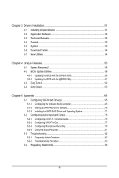
... 52 3-4 Contact...53 3-5 System...53 3-6 Download Center 54 3-7 New Utilities...54 Chapter 4 Unique Features 55 4-1 Xpress Recovery2 55 4-2 BIOS Update Utilities 58 4-2-1 Updating the BIOS with the Q-Flash Utility 58 4-2-2 Updating the BIOS with the @BIOS Utility 61 4-3 EasyTune 6...62 4-4 Auto Green...63 Chapter 5 Appendix...65 5-1 Configuring SATA Hard Drive(s 65 5-1-1 Configuring the Onboard...
... 52 3-4 Contact...53 3-5 System...53 3-6 Download Center 54 3-7 New Utilities...54 Chapter 4 Unique Features 55 4-1 Xpress Recovery2 55 4-2 BIOS Update Utilities 58 4-2-1 Updating the BIOS with the Q-Flash Utility 58 4-2-2 Updating the BIOS with the @BIOS Utility 61 4-3 EasyTune 6...62 4-4 Auto Green...63 Chapter 5 Appendix...65 5-1 Configuring SATA Hard Drive(s 65 5-1-1 Configuring the Onboard...

Manual
Page 8
GA-M52LT-D3/GA-M52LT-S3P Motherboard Block Diagram AM3 CPU CPU CLK+/- (200 MHz) DDR3 1666(O.C.)/1333/1066 MHz Dual Channel Memory PCIe CLK (100 MHz) 1 PCI Express x16 Hyper Transport PCI Express Bus x1 x1 PCIe CLK (100 MHz) 2 PCI Express x1 2 SATA 3Gb/s NVIDIA® nForce 520LE Realtek RTL8201EL RJ45 LAN 8 USB 2.0/1.1 ATA-133/100/66/33 IDE Channel PCI Bus CODEC LPC Bus iTE IT8720 Dual BIOS Floppy COM Port LPT Port PS/2 KB/Mouse Surround Speaker Out Center/Subwoofer Speaker Out Side Speaker Out MIC Line Out Line In S/PDIF In S/PDIF Out 4 PCI PCI CLK (33 MHz) - 8 -
GA-M52LT-D3/GA-M52LT-S3P Motherboard Block Diagram AM3 CPU CPU CLK+/- (200 MHz) DDR3 1666(O.C.)/1333/1066 MHz Dual Channel Memory PCIe CLK (100 MHz) 1 PCI Express x16 Hyper Transport PCI Express Bus x1 x1 PCIe CLK (100 MHz) 2 PCI Express x1 2 SATA 3Gb/s NVIDIA® nForce 520LE Realtek RTL8201EL RJ45 LAN 8 USB 2.0/1.1 ATA-133/100/66/33 IDE Channel PCI Bus CODEC LPC Bus iTE IT8720 Dual BIOS Floppy COM Port LPT Port PS/2 KB/Mouse Surround Speaker Out Center/Subwoofer Speaker Out Side Speaker Out MIC Line Out Line In S/PDIF In S/PDIF Out 4 PCI PCI CLK (33 MHz) - 8 -

Manual
Page 11
...-45 port 6 x audio jacks (Center/Subwoofer Speaker Out/Rear Speaker Out/ Side Speaker Out/Line In/Line Out/Microphone) I/O Controller w iTE IT8720 chip Hardware Monitor w w w w w w BIOS w w w w Unique Features w w w w w w w w w System voltage detection CPU/System temperature detection CPU/System fan speed detection CPU/System overheating warning CPU/System fan fail warning CPU/System...
...-45 port 6 x audio jacks (Center/Subwoofer Speaker Out/Rear Speaker Out/ Side Speaker Out/Line In/Line Out/Microphone) I/O Controller w iTE IT8720 chip Hardware Monitor w w w w w w BIOS w w w w Unique Features w w w w w w w w w System voltage detection CPU/System temperature detection CPU/System fan speed detection CPU/System overheating warning CPU/System fan fail warning CPU/System...

Manual
Page 15
...sockets and supports Dual Channel Technology. When enabling Dual Channel mode with two or four memory modules, it is installed, the BIOS will double the original memory bandwidth. If you are divided into two channels and each channel has two memory sockets as following... DDR3_4 DDR3_1 DDR3_2 DDR3_3 DDR3_4 Two Modules DS/SS DS/SS - - - - - - - - Dual Channel mode cannot be used . (Go to GIGABYTE's website for optimum performance. - 15 - Enabling Dual Channel memory mode will automatically detect the specifications and capacity of the same capacity, brand, speed, and chips...
...sockets and supports Dual Channel Technology. When enabling Dual Channel mode with two or four memory modules, it is installed, the BIOS will double the original memory bandwidth. If you are divided into two channels and each channel has two memory sockets as following... DDR3_4 DDR3_1 DDR3_2 DDR3_3 DDR3_4 Two Modules DS/SS DS/SS - - - - - - - - Dual Channel mode cannot be used . (Go to GIGABYTE's website for optimum performance. - 15 - Enabling Dual Channel memory mode will automatically detect the specifications and capacity of the same capacity, brand, speed, and chips...

Manual
Page 17
... cover from the slot. - 17 - Make sure the metal contacts on the card until it is fully seated in the slot. 3. If necessary, go to BIOS Setup to prevent hardware damage. Install the driver provided with the slot, and press down on the top edge of the card until it is...; Make sure the motherboard supports the expansion card. 1-5 Installing an Expansion Card Read the following guidelines before installing an expansion card to make any required BIOS changes for your expansion card in the expansion slot. 1.
... cover from the slot. - 17 - Make sure the metal contacts on the card until it is fully seated in the slot. 3. If necessary, go to BIOS Setup to prevent hardware damage. Install the driver provided with the slot, and press down on the top edge of the card until it is...; Make sure the motherboard supports the expansion card. 1-5 Installing an Expansion Card Read the following guidelines before installing an expansion card to make any required BIOS changes for your expansion card in the expansion slot. 1.

Manual
Page 24
... MSG/PWR (Message/Power/Sleep LED, Yellow/Purple): System Status LED Connects to the pin assignments below. S1 Blinking tem is detected, the BIOS may differ by issuing a beep code. The LED keeps blinking when the sys- A front panel module mainly consists of power switch, reset ...This function requires a chassis with a chassis intrusion switch/sensor. When connecting your system using the power switch (refer to Chapter 2, "BIOS Setup," "Power Management Setup," for information about beep codes. • HD (Hard Drive Activity LED, Blue) Connects to indicate the problem.
... MSG/PWR (Message/Power/Sleep LED, Yellow/Purple): System Status LED Connects to the pin assignments below. S1 Blinking tem is detected, the BIOS may differ by issuing a beep code. The LED keeps blinking when the sys- A front panel module mainly consists of power switch, reset ...This function requires a chassis with a chassis intrusion switch/sensor. When connecting your system using the power switch (refer to Chapter 2, "BIOS Setup," "Power Management Setup," for information about beep codes. • HD (Hard Drive Activity LED, Blue) Connects to indicate the problem.

Manual
Page 27
... damage to the USB bracket. 15) CLR_CMOS (Clearing CMOS Jumper) Use this jumper to touch the two pins for BIOS configurations). - 27 - date information and BIOS configurations) and reset the CMOS values to remove the jumper cap from the power outlet before clearing the CMOS values. ... (e.g. Failure to do so may cause damage to the motherboard. • After system restart, go to BIOS Setup to load factory defaults (select Load Optimized Defaults) or manually configure the BIOS settings (refer to USB 2.0/1.1 specification. 14) F_USB1/F_USB2 (USB Headers) The headers conform to Chapter...
... damage to the USB bracket. 15) CLR_CMOS (Clearing CMOS Jumper) Use this jumper to touch the two pins for BIOS configurations). - 27 - date information and BIOS configurations) and reset the CMOS values to remove the jumper cap from the power outlet before clearing the CMOS values. ... (e.g. Failure to do so may cause damage to the motherboard. • After system restart, go to BIOS Setup to load factory defaults (select Load Optimized Defaults) or manually configure the BIOS settings (refer to USB 2.0/1.1 specification. 14) F_USB1/F_USB2 (USB Headers) The headers conform to Chapter...

Manual
Page 28
.... Gently remove the battery from the battery holder and wait for one . 16) BAT (Battery) The battery provides power to keep the values (such as BIOS configurations, date, and time information) in the CMOS when the computer is replaced with an incorrect model. • Contact the place of purchase or local...
.... Gently remove the battery from the battery holder and wait for one . 16) BAT (Battery) The battery provides power to keep the values (such as BIOS configurations, date, and time information) in the CMOS when the computer is replaced with an incorrect model. • Contact the place of purchase or local...

Manual
Page 29
To upgrade the BIOS, use either the GIGABYTE Q-Flash or @BIOS utility. • Q-Flash allows the user to Chapter 4, "BIOS Update Utilities." • Because BIOS flashing is potentially risky, if you do it is recommended that you not flash the BIOS. To flash the BIOS, do not encounter problems using the Q-Flash and @BIOS utilities, refer to quickly and...
To upgrade the BIOS, use either the GIGABYTE Q-Flash or @BIOS utility. • Q-Flash allows the user to Chapter 4, "BIOS Update Utilities." • Because BIOS flashing is potentially risky, if you do it is recommended that you not flash the BIOS. To flash the BIOS, do not encounter problems using the Q-Flash and @BIOS utilities, refer to quickly and...

Manual
Page 30
... The following screens may appear when the computer boots. Motherboard Model BIOS Version GA-M52LT-D3 E3 . . . . : BIOS Setup : XpressRecovery2 : Boot Menu : Qflash 05/10/2010-NF-520LE-6A61KG0LC-00 Function Keys Function Keys Function Keys: : POST SCREEN Press the key to show the BIOS POST screen at system startup, refer to the instructions on the...
... The following screens may appear when the computer boots. Motherboard Model BIOS Version GA-M52LT-D3 E3 . . . . : BIOS Setup : XpressRecovery2 : Boot Menu : Qflash 05/10/2010-NF-520LE-6A61KG0LC-00 Function Keys Function Keys Function Keys: : POST SCREEN Press the key to show the BIOS POST screen at system startup, refer to the instructions on the...
Manual
Page 31
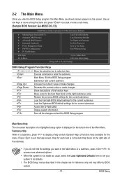
...the screen. Use arrow keys to move among the items and press to accept or enter a sub-menu. (Sample BIOS Version: GA-M52LT-D3, E3) CMOS Setup Utility-Copyright (C) 1984-2010 Award Software MB Intelligent Tweaker(M.I.T.) Standard CMOS Features Advanced... BIOS Features Integrated Peripherals Power Management Setup PnP/PCI Configurations PC Health Status ESC: Quit F8:...
...the screen. Use arrow keys to move among the items and press to accept or enter a sub-menu. (Sample BIOS Version: GA-M52LT-D3, E3) CMOS Setup Utility-Copyright (C) 1984-2010 Award Software MB Intelligent Tweaker(M.I.T.) Standard CMOS Features Advanced... BIOS Features Integrated Peripherals Power Management Setup PnP/PCI Configurations PC Health Status ESC: Quit F8:...

Manual
Page 32
... and date, hard drive types, floppy disk drive types, and the type of errors that stop the system boot, etc. Advanced BIOS Features Use this menu to configure the device boot order, advanced features available on the CPU, and the primary display adapter. Integrated ... PnP/PCI Configurations Use this menu to configure the system's PCI & PnP resources. PC Health Status Use this menu to the system and BIOS Setup. A user password only allows you to restrict access to see information about autodetected system/CPU temperature, system voltage and fan speed, etc. ...
... and date, hard drive types, floppy disk drive types, and the type of errors that stop the system boot, etc. Advanced BIOS Features Use this menu to configure the device boot order, advanced features available on the CPU, and the primary display adapter. Integrated ... PnP/PCI Configurations Use this menu to configure the system's PCI & PnP resources. PC Health Status Use this menu to the system and BIOS Setup. A user password only allows you to restrict access to see information about autodetected system/CPU temperature, system voltage and fan speed, etc. ...

Manual
Page 33
PCIE Clock(MHz) Allows you to boot. Auto lets BIOS automatically set the memory clock. Manual allows the memory clock control item below to be set in accordance with the overclock settings you not to ... result in system's failure to alter the clock ratio for the installed CPU. Set Memory Clock Determines whether to manually set the PCIe clock frequency. BIOS Setup Important It is highly recommended that the CPU frequency be configurable. (Default: Auto) - 33 - The adjustable range is dependent on the CPU being used...
PCIE Clock(MHz) Allows you to boot. Auto lets BIOS automatically set the memory clock. Manual allows the memory clock control item below to be set in accordance with the overclock settings you not to ... result in system's failure to alter the clock ratio for the installed CPU. Set Memory Clock Determines whether to manually set the PCIe clock frequency. BIOS Setup Important It is highly recommended that the CPU frequency be configurable. (Default: Auto) - 33 - The adjustable range is dependent on the CPU being used...

Manual
Page 34
... Cycle Time x RAS to X8.00. Options are: Auto (default), Manual. X4.00 Sets Memory Clock to CAS R/W Delay Options are : Auto (default), 4T~12T. BIOS Setup - 34 - Auto --
... Cycle Time x RAS to X8.00. Options are: Auto (default), Manual. X4.00 Sets Memory Clock to CAS R/W Delay Options are : Auto (default), 4T~12T. BIOS Setup - 34 - Auto --

Manual
Page 35
...), 5T~12T. CPU NB VID Control Allows you to set the CPU voltage. CPU Voltage Control Allows you to set the CPU Northbridge VID voltage. BIOS Setup TwTr Command Delay Options are : Auto (default), 4T~7T. Precharge Time Options are : Auto (default), 4T~7T. Auto sets the CPU voltage as required...
...), 5T~12T. CPU NB VID Control Allows you to set the CPU voltage. CPU Voltage Control Allows you to set the CPU Northbridge VID voltage. BIOS Setup TwTr Command Delay Options are : Auto (default), 4T~7T. Precharge Time Options are : Auto (default), 4T~7T. Auto sets the CPU voltage as required...

Manual
Page 36
... Large. IDE Channel 0 Master/Slave IDE HDD Auto-Detection Press to autodetect the parameters of the two methods below : • Auto Lets the BIOS automatically detect IDE/SATA devices during the POST. (Default) • None If no IDE/SATA devices are used , set the time. IDE Channel... 2, 3 Master IDE Auto-Detection Press to autodetect the parameters of the device during the POST for faster system startup. BIOS Setup - 36 - Access Mode Sets the hard drive access mode. Access Mode Sets the hard drive access mode. For example, 1 p.m. ...
... Large. IDE Channel 0 Master/Slave IDE HDD Auto-Detection Press to autodetect the parameters of the two methods below : • Auto Lets the BIOS automatically detect IDE/SATA devices during the POST. (Default) • None If no IDE/SATA devices are used , set the time. IDE Channel... 2, 3 Master IDE Auto-Detection Press to autodetect the parameters of the device during the POST for faster system startup. BIOS Setup - 36 - Access Mode Sets the hard drive access mode. Access Mode Sets the hard drive access mode. For example, 1 p.m. ...

Manual
Page 37
...25", 1.2M/5.25", 720K/3.5", 1.44M/3.5", 2.88M/3.5". The following fields display your system. Sector Number of cylinders. Base Memory Also called conventional memory. BIOS Setup Head Number of extended memory. - 37 - If you to select the type of the currently installed hard drive. Halt On Allows you to...will not stop for a keyboard error but stop for all other errors. Memory These fields are read-only and are determined by the BIOS POST. Extended Memory The amount of heads. Drive A Allows you do not install a floppy disk drive, set this item to determine...
...25", 1.2M/5.25", 720K/3.5", 1.44M/3.5", 2.88M/3.5". The following fields display your system. Sector Number of cylinders. Base Memory Also called conventional memory. BIOS Setup Head Number of extended memory. - 37 - If you to select the type of the currently installed hard drive. Halt On Allows you to...will not stop for a keyboard error but stop for all other errors. Memory These fields are read-only and are determined by the BIOS POST. Extended Memory The amount of heads. Drive A Allows you do not install a floppy disk drive, set this item to determine...

Manual
Page 38
... below to run multiple operating systems and applications in system halt state. Capability Away Mode Full Screen LOGO Show Backup BIOS Image to reduce heat output from your computer and its power consumption. (Default) Disabled Disables this feature. Auto Lets the...ESC: Exit F1: General Help F7: Optimized Defaults AMD C1E Support (Note) Enables or disables the C1E CPU power-saving function in independent partitions. BIOS Setup - 38 - CPU Unlock (Note) Allows you to determine whether unlock hidden CPU cores. (Default: Disabled) CPU core Control Allows you ...
... below to run multiple operating systems and applications in system halt state. Capability Away Mode Full Screen LOGO Show Backup BIOS Image to reduce heat output from your computer and its power consumption. (Default) Disabled Disables this feature. Auto Lets the...ESC: Exit F1: General Help F7: Optimized Defaults AMD C1E Support (Note) Enables or disables the C1E CPU power-saving function in independent partitions. BIOS Setup - 38 - CPU Unlock (Note) Allows you to determine whether unlock hidden CPU cores. (Default: Disabled) CPU core Control Allows you ...


