
Manual
Page 3
... or download the information on/from the Support\Motherboard\Technology Guide page on your motherboard revision before updating motherboard BIOS, drivers, or when looking for technical information. Example: The trademarks mentioned in any form or by GIGABYTE without GIGABYTE's prior written permission. Check your motherboard looks like this manual are legally registered to...
... or download the information on/from the Support\Motherboard\Technology Guide page on your motherboard revision before updating motherboard BIOS, drivers, or when looking for technical information. Example: The trademarks mentioned in any form or by GIGABYTE without GIGABYTE's prior written permission. Check your motherboard looks like this manual are legally registered to...

Manual
Page 4
Table of Contents Box Contents ...6 OptionalItems ...6 GA-M52L-S3 Motherboard Layout 7 Block Diagram ...8 Chapter 1 Hardware Installation 9 1-1 Installation Precautions 9 1-2 Product Specifications 10 1-3 Installing the CPU and CPU Cooler 12 ... Memory 16 1-5 Installing an Expansion Card 17 1-6 Back Panel Connectors 18 1-7 Internal Connectors 20 Chapter 2 BIOS Setup 31 2-1 Startup Screen 32 2-2 The Main Menu 33 2-3 Standard CMOS Features 35 2-4 Advanced BIOS Features 37 2-5 IntegratedPeripherals 39 2-6 Power Management Setup 42 2-7 PnP/PCI Configurations 44 2-8 PC Health Status ...
Table of Contents Box Contents ...6 OptionalItems ...6 GA-M52L-S3 Motherboard Layout 7 Block Diagram ...8 Chapter 1 Hardware Installation 9 1-1 Installation Precautions 9 1-2 Product Specifications 10 1-3 Installing the CPU and CPU Cooler 12 ... Memory 16 1-5 Installing an Expansion Card 17 1-6 Back Panel Connectors 18 1-7 Internal Connectors 20 Chapter 2 BIOS Setup 31 2-1 Startup Screen 32 2-2 The Main Menu 33 2-3 Standard CMOS Features 35 2-4 Advanced BIOS Features 37 2-5 IntegratedPeripherals 39 2-6 Power Management Setup 42 2-7 PnP/PCI Configurations 44 2-8 PC Health Status ...

Manual
Page 5
... 54 3-3 Driver CD Information 54 3-4 Hardware Information 55 3-5 Contact Us ...55 Chapter 4 Unique Features 57 4-1 Xpress Recovery2 57 4-2 BIOS Update Utilities 62 4-2-1 Updating the BIOS with the Q-Flash Utility 62 4-2-2 Updating the BIOS with the @BIOS Utility 65 4-3 EasyTune 5 ...67 4-4 Windows Vista ReadyBoost 68 Chapter 5 Appendix ...69 5-1 Configuring SATA Hard Drive(s 69 5-1-1 Configuring the...
... 54 3-3 Driver CD Information 54 3-4 Hardware Information 55 3-5 Contact Us ...55 Chapter 4 Unique Features 57 4-1 Xpress Recovery2 57 4-2 BIOS Update Utilities 62 4-2-1 Updating the BIOS with the Q-Flash Utility 62 4-2-2 Updating the BIOS with the @BIOS Utility 65 4-3 EasyTune 5 ...67 4-4 Windows Vista ReadyBoost 68 Chapter 5 Appendix ...69 5-1 Configuring SATA Hard Drive(s 69 5-1-1 Configuring the...

Manual
Page 7
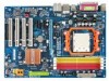
GA-M52L-S3 Motherboard Layout KB_MS COAXIAL Socket AM2 ATX COMA LPT USB R_USB LAN ATX_12V CPU_FAN AUDIO F_AUDIO PCIE_16 GA-M52L-S3 DDRII_1 DDRII_2 DDRII_3 DDRII_4 SPDIF_O Realtek PCIE_1 8201CL BIOS BATTERY PCIE_2 CODEC CLR_CMOS NVIDIA® PCI1 nForce 520LE (Geforce 6100/ nForce 430) CD_IN SPDIF_I PCI2 IDE IT8716 CI PCI3 PCI4 FDD F_USB2 F_USB1 SYS_FAN F_PANEL PWR_LED SATAII1 SATAII0 - 7 -
GA-M52L-S3 Motherboard Layout KB_MS COAXIAL Socket AM2 ATX COMA LPT USB R_USB LAN ATX_12V CPU_FAN AUDIO F_AUDIO PCIE_16 GA-M52L-S3 DDRII_1 DDRII_2 DDRII_3 DDRII_4 SPDIF_O Realtek PCIE_1 8201CL BIOS BATTERY PCIE_2 CODEC CLR_CMOS NVIDIA® PCI1 nForce 520LE (Geforce 6100/ nForce 430) CD_IN SPDIF_I PCI2 IDE IT8716 CI PCI3 PCI4 FDD F_USB2 F_USB1 SYS_FAN F_PANEL PWR_LED SATAII1 SATAII0 - 7 -

Manual
Page 8
Block Diagram PCIe CLK (100 MHz) 1 PCI Express x16 AMD Socket AM2 CPU CPU CLK+/-(200 MHz) DDR2 800/667/533/400 MHz DIMM Dual Channel Memory Hyper Transport PCI Express x16 PCI Express x1 Bus x1 x1 PCIe CLK (100 MHz) 2 PCI Express x1 PCI Bus 4 PCI NVIDIA® nForce 520LE (Geforce 6100/ nForce 430) RTL 8201CL LAN RJ45 2 SATA 3Gb/s ATA-133/100/66/33 IDE Channel CODEC LPC BUS IT8716 BIOS Floppy LPT Port COM Port 8 USB Ports PS/2 KB/Mouse Surround Speaker Out Center/Subwoofer Spear Out Side Speaker Out MIC Line-Out Line-In SPDIF In SPDIF Out PCI CLK (33 MHz) - 8 -
Block Diagram PCIe CLK (100 MHz) 1 PCI Express x16 AMD Socket AM2 CPU CPU CLK+/-(200 MHz) DDR2 800/667/533/400 MHz DIMM Dual Channel Memory Hyper Transport PCI Express x16 PCI Express x1 Bus x1 x1 PCIe CLK (100 MHz) 2 PCI Express x1 PCI Bus 4 PCI NVIDIA® nForce 520LE (Geforce 6100/ nForce 430) RTL 8201CL LAN RJ45 2 SATA 3Gb/s ATA-133/100/66/33 IDE Channel CODEC LPC BUS IT8716 BIOS Floppy LPT Port COM Port 8 USB Ports PS/2 KB/Mouse Surround Speaker Out Center/Subwoofer Spear Out Side Speaker Out MIC Line-Out Line-In SPDIF In SPDIF Out PCI CLK (33 MHz) - 8 -

Manual
Page 11
...warning Š CPU/System fan speed control (Note 2) Š 1 x 4 Mbit flash Š Use of licensed AWARD BIOS Š PnP 1.0a, DMI 2.0, SM BIOS 2.4, ACPI 1.0b Š Support for @BIOS Š Support for Download Center Š Support for Q-Flash Š Support for EasyTune (Note 3) Š Support for ...Xpress Install Š Support for Xpress Recovery2 Š Support for Virtual Dual BIOS Š Norton Internet Security (OEM version) Š Support for Microsoft® Windows® Vista/XP/2000 Š ATX form factor; 30.5cm ...
...warning Š CPU/System fan speed control (Note 2) Š 1 x 4 Mbit flash Š Use of licensed AWARD BIOS Š PnP 1.0a, DMI 2.0, SM BIOS 2.4, ACPI 1.0b Š Support for @BIOS Š Support for Download Center Š Support for Q-Flash Š Support for EasyTune (Note 3) Š Support for ...Xpress Install Š Support for Xpress Recovery2 Š Support for Virtual Dual BIOS Š Norton Internet Security (OEM version) Š Support for Microsoft® Windows® Vista/XP/2000 Š ATX form factor; 30.5cm ...

Manual
Page 15
... Modules DS/SS DS/SS DS/SS DS/SS (SS=Single-Sided, DS=Double-Sided, "- -"=No Memory) If two memory modules are to GIGABYTE's website for optimum performance. - 15 - Dual Channel mode cannot be used and installed in Dual Channel mode. 1. It is recommended that the .... • Memory modules have a foolproof design. Hardware Installation If you install them in only one DDR2 memory module is installed, the BIOS will double the original memory bandwidth. DDRII_1 DDRII_2 DDRII_3 DDRII_4 Due to CPU limitation, read the following guidelines before you begin to install the...
... Modules DS/SS DS/SS DS/SS DS/SS (SS=Single-Sided, DS=Double-Sided, "- -"=No Memory) If two memory modules are to GIGABYTE's website for optimum performance. - 15 - Dual Channel mode cannot be used and installed in Dual Channel mode. 1. It is recommended that the .... • Memory modules have a foolproof design. Hardware Installation If you install them in only one DDR2 memory module is installed, the BIOS will double the original memory bandwidth. DDRII_1 DDRII_2 DDRII_3 DDRII_4 Due to CPU limitation, read the following guidelines before you begin to install the...

Manual
Page 17
...expansion card. • Always turn off the computer and unplug the power cord from the power outlet before you begin to make any required BIOS changes for your expansion card(s). 7. Align the card with the expansion card in your computer. Install the driver provided with the slot, ...the PCI Express x16 slot. Secure the card's metal bracket to correctly install your expansion card in the slot. 3. If necessary, go to BIOS Setup to install an expansion card: • Make sure the motherboard supports the expansion card. Carefully read the manual that supports your card. ...
...expansion card. • Always turn off the computer and unplug the power cord from the power outlet before you begin to make any required BIOS changes for your expansion card(s). 7. Align the card with the expansion card in your computer. Install the driver provided with the slot, ...the PCI Express x16 slot. Secure the card's metal bracket to correctly install your expansion card in the slot. 3. If necessary, go to BIOS Setup to install an expansion card: • Make sure the motherboard supports the expansion card. Carefully read the manual that supports your card. ...
Manual
Page 24
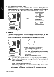
... the power cord. 2. Pin No. 1 2 3 Definition MPD+ MPDMPD- 1 System Status LED S0 On S1 Blinking S3/S4/S5 Off 9) BATTERY The battery provides power to keep the values (such as BIOS configurations, date, and time information) in the power cord and restart your computer. • Always turn off when... used to connect a system power LED on when the system is operating. Gently remove the battery from the battery holder and wait for one . GA-M52L-S3 Motherboard - 24 - Replace the battery when the battery voltage drops to a low level, or the CMOS values may not be accurate or may...
... the power cord. 2. Pin No. 1 2 3 Definition MPD+ MPDMPD- 1 System Status LED S0 On S1 Blinking S3/S4/S5 Off 9) BATTERY The battery provides power to keep the values (such as BIOS configurations, date, and time information) in the power cord and restart your computer. • Always turn off when... used to connect a system power LED on when the system is operating. Gently remove the battery from the battery holder and wait for one . GA-M52L-S3 Motherboard - 24 - Replace the battery when the battery voltage drops to a low level, or the CMOS values may not be accurate or may...
Manual
Page 25
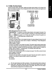
... front panel. One single short beep will be heard if no problem is operating. When connecting your system using the power switch (refer to Chapter 2, "BIOS Setup," "Power Management Setup," for information about beep codes. • HD (IDE Hard Drive Activity LED, Blue) Connects to the hard drive activity LED... on the chassis front panel. If a problem is in S3/S4/S5 Off S3/S4 sleep state or powered off your chassis front panel module to the power status indicator on the chassis front panel. Press the reset...
... front panel. One single short beep will be heard if no problem is operating. When connecting your system using the power switch (refer to Chapter 2, "BIOS Setup," "Power Management Setup," for information about beep codes. • HD (IDE Hard Drive Activity LED, Blue) Connects to the hard drive activity LED... on the chassis front panel. If a problem is in S3/S4/S5 Off S3/S4 sleep state or powered off your chassis front panel module to the power status indicator on the chassis front panel. Press the reset...
Manual
Page 29
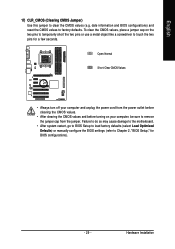
... do so may cause damage to the motherboard. • After system restart, go to BIOS Setup to load factory defaults (select Load Optimized Defaults) or manually configure the BIOS settings (refer to Chapter 2, "BIOS Setup," for a few seconds. English 17) CLR_CMOS (Clearing CMOS Jumper) Use this jumper...Values • Always turn off your computer, be sure to clear the CMOS values (e.g. date information and BIOS configurations) and reset the CMOS values to touch the two pins for BIOS configurations). - 29 - To clear the CMOS values, place a jumper cap on your computer and unplug ...
... do so may cause damage to the motherboard. • After system restart, go to BIOS Setup to load factory defaults (select Load Optimized Defaults) or manually configure the BIOS settings (refer to Chapter 2, "BIOS Setup," for a few seconds. English 17) CLR_CMOS (Clearing CMOS Jumper) Use this jumper...Values • Always turn off your computer, be sure to clear the CMOS values (e.g. date information and BIOS configurations) and reset the CMOS values to touch the two pins for BIOS configurations). - 29 - To clear the CMOS values, place a jumper cap on your computer and unplug ...

Manual
Page 31
... to boot. If this chapter or introductions of BIOS from the Internet and updates the BIOS. To upgrade the BIOS, use either the GIGABYTE Q-Flash or @BIOS utility. • Q-Flash allows the user to quickly and easily upgrade or back up BIOS without entering the operating system. • @BIOS is turned off, the battery on using the...
... to boot. If this chapter or introductions of BIOS from the Internet and updates the BIOS. To upgrade the BIOS, use either the GIGABYTE Q-Flash or @BIOS utility. • Q-Flash allows the user to quickly and easily upgrade or back up BIOS without entering the operating system. • @BIOS is turned off, the battery on using the...

Manual
Page 32
... to access the Q-Flash utility in Boot Menu is effective for subsequent access to the instructions on the Full Screen LOGO Show item on BIOS Setup settings. GA-M52L-S3 F6b . . . . : BIOS Setup/Q-Flash : XpressRecovery2 : Boot Menu : Qflash 03/04/2008-NV-MCP61-6A61KG07C-00 Function Keys Function Keys: : POST Screen Press the key to...
... to access the Q-Flash utility in Boot Menu is effective for subsequent access to the instructions on the Full Screen LOGO Show item on BIOS Setup settings. GA-M52L-S3 F6b . . . . : BIOS Setup/Q-Flash : XpressRecovery2 : Boot Menu : Qflash 03/04/2008-NV-MCP61-6A61KG07C-00 Function Keys Function Keys: : POST Screen Press the key to...

Manual
Page 33
...Disk Type... Press to exit the help screen (General Help) of function keys available for reference only and may differ by BIOS version. - 33 - BIOS Setup BIOS Setup Program Function Keys Move the selection bar to select an item Execute command or enter the submenu Main Menu: Exit ...are for the menu. Help for the current submenus Access the Q-Flash utility Display system information Save all the changes and exit the BIOS Setup program Main Menu Help The onscreen description of a highlighted setup option is displayed on the bottom line of the submenu. •...
...Disk Type... Press to exit the help screen (General Help) of function keys available for reference only and may differ by BIOS version. - 33 - BIOS Setup BIOS Setup Program Function Keys Move the selection bar to select an item Execute command or enter the submenu Main Menu: Exit ...are for the menu. Help for the current submenus Access the Q-Flash utility Display system information Save all the changes and exit the BIOS Setup program Main Menu Help The onscreen description of a highlighted setup option is displayed on the bottom line of the submenu. •...

Manual
Page 34
...Intelligent Tweaker(M.I.T.) Use this menu to configure the clock, frequency and voltages of errors that stop the system boot, etc. „ Advanced BIOS Features Use this menu to configure the device boot order, advanced features available on the CPU, and the primary display adapter. „ .... „ Set User Password Change, set , or disable password. Pressing to the confirmation message will exit BIOS Setup. (Pressing can also carry out this task.) GA-M52L-S3 Motherboard - 34 - English „ Standard CMOS Features Use this menu to configure the system time and date, hard drive...
...Intelligent Tweaker(M.I.T.) Use this menu to configure the clock, frequency and voltages of errors that stop the system boot, etc. „ Advanced BIOS Features Use this menu to configure the device boot order, advanced features available on the CPU, and the primary display adapter. „ .... „ Set User Password Change, set , or disable password. Pressing to the confirmation message will exit BIOS Setup. (Pressing can also carry out this task.) GA-M52L-S3 Motherboard - 34 - English „ Standard CMOS Features Use this menu to configure the system time and date, hard drive...
Manual
Page 35
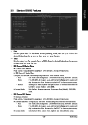
... Auto (default), Large. - 35 - IDE Channel 0 Master/Slave Configure your IDE/SATA devices using one of the two methods below : • Auto Lets BIOS automatically detect IDE/SATA devices during the POST for faster system startup. Select the desired field and use the up arrow or down arrow key... 2/3 Master IDE Auto-Detection Press to autodetect the parameters of the hard drive when the hard drive access mode is set to set the date. BIOS Setup For example, 1 p.m. The date format is 13:0:0. Time Sets the system time. is week (read-only), month, date and year....
... Auto (default), Large. - 35 - IDE Channel 0 Master/Slave Configure your IDE/SATA devices using one of the two methods below : • Auto Lets BIOS automatically detect IDE/SATA devices during the POST for faster system startup. Select the desired field and use the up arrow or down arrow key... 2/3 Master IDE Auto-Detection Press to autodetect the parameters of the hard drive when the hard drive access mode is set to set the date. BIOS Setup For example, 1 p.m. The date format is 13:0:0. Time Sets the system time. is week (read-only), month, date and year....

Manual
Page 36
...of heads. GA-M52L-S3 Motherboard - 36 - Head Number of sectors. Drive A Allows you wish to enter the parameters manually, refer to specify whether the installed floppy disk drive is 3-mode floppy disk drive, a Japanese standard floppy disk drive. All Errors Whenever the BIOS detects a non... Memory The amount of cylinders. Precomp Write precompensation cylinder. Floppy 3 Mode Support Allows you to None. Options are determined by the BIOS POST. All, But Keyboard The system boot will not stop for a keyboard error but stop for all other errors. (Default) ...
...of heads. GA-M52L-S3 Motherboard - 36 - Head Number of sectors. Drive A Allows you wish to enter the parameters manually, refer to specify whether the installed floppy disk drive is 3-mode floppy disk drive, a Japanese standard floppy disk drive. All Errors Whenever the BIOS detects a non... Memory The amount of cylinders. Precomp Write precompensation cylinder. Floppy 3 Mode Support Allows you to None. Options are determined by the BIOS POST. All, But Keyboard The system boot will not stop for a keyboard error but stop for all other errors. (Default) ...
Manual
Page 37
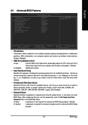
...hard drive, then press the plus key (or ) or the minus key (or ) to run multiple operating systems and applications in the BIOS Main Menu. Hard Disk Boot Priority Specifies the sequence of loading the operating system from the installed hard drives. Options are: Floppy, LS120... CDROM, ZIP, USB-FDD, USB-ZIP, USB-CDROM, USB-HDD, Legacy LAN, Disabled. English 2-4 Advanced BIOS Features CMOS Setup Utility-Copyright (C) 1984-2008 Award Software Advanced BIOS Features Virtualization AMD K8 Cool&Quiet control ` Hard Disk Boot Priority First Boot Device Second Boot Device Third Boot ...
...hard drive, then press the plus key (or ) or the minus key (or ) to run multiple operating systems and applications in the BIOS Main Menu. Hard Disk Boot Priority Specifies the sequence of loading the operating system from the installed hard drives. Options are: Floppy, LS120... CDROM, ZIP, USB-FDD, USB-ZIP, USB-CDROM, USB-HDD, Legacy LAN, Disabled. English 2-4 Advanced BIOS Features CMOS Setup Utility-Copyright (C) 1984-2008 Award Software Advanced BIOS Features Virtualization AMD K8 Cool&Quiet control ` Hard Disk Boot Priority First Boot Device Second Boot Device Third Boot ...

Manual
Page 39
...` KLJI: Move Enter: Select F5: Previous Values +/-/PU/PD: Value F10: Save F6: Fail-Safe Defaults ESC: Exit F1: General Help F7: Optimized Defaults - 39 - BIOS Setup Options are: SHADOW (default), Base Memory (640K). English 2-5 Integrated Peripherals CMOS Setup Utility-Copyright (C) 1984-2008 Award Software Integrated Peripherals On-Chip IDE Channel...
...` KLJI: Move Enter: Select F5: Previous Values +/-/PU/PD: Value F10: Save F6: Fail-Safe Defaults ESC: Exit F1: General Help F7: Optimized Defaults - 39 - BIOS Setup Options are: SHADOW (default), Base Memory (640K). English 2-5 Integrated Peripherals CMOS Setup Utility-Copyright (C) 1984-2008 Award Software Integrated Peripherals On-Chip IDE Channel...

Manual
Page 41
English USB Keyboard Support Allows USB keyboard to be used in MS-DOS. (Default: Disabled) USB Mouse Support Allows USB mouse to be used in MS-DOS. (Default: Disabled) Legacy USB storage detect Determines whether to detect USB storage devices, including USB flash drives and USB hard drives during the POST. (Default: Enabled) - 41 - BIOS Setup
English USB Keyboard Support Allows USB keyboard to be used in MS-DOS. (Default: Disabled) USB Mouse Support Allows USB mouse to be used in MS-DOS. (Default: Disabled) Legacy USB storage detect Determines whether to detect USB storage devices, including USB flash drives and USB hard drives during the POST. (Default: Enabled) - 41 - BIOS Setup


