User Manual
Page 4
...GA-K8NSC-939 Motherboard Layout 6 Block Diagram ...7 Chapter 1 Hardware Installation 9 1-1 Considerations Prior to Installation 9 1-2 Feature Summary 10 1-3 Installation of the CPU and Heatsink 12 1-3-1 Installation of the CPU 12 1-3-2 Installation of the Heatsink 13 1-4 Installation of Memory 14 1-5 Installation of Expansion Cards 16 1-6 I/O Back Panel Introduction 17 1-7 Connectors Introduction 18 Chapter 2 BIOS Setup 29 The Main Menu (Example BIOS Version:E1 30 2-1 Standard CMOS Features 32 2-2 Advanced BIOS Features 34 2-3 IntegratedPeripherals 36 2-4 Power Management Setup...
...GA-K8NSC-939 Motherboard Layout 6 Block Diagram ...7 Chapter 1 Hardware Installation 9 1-1 Considerations Prior to Installation 9 1-2 Feature Summary 10 1-3 Installation of the CPU and Heatsink 12 1-3-1 Installation of the CPU 12 1-3-2 Installation of the Heatsink 13 1-4 Installation of Memory 14 1-5 Installation of Expansion Cards 16 1-6 I/O Back Panel Introduction 17 1-7 Connectors Introduction 18 Chapter 2 BIOS Setup 29 The Main Menu (Example BIOS Version:E1 30 2-1 Standard CMOS Features 32 2-2 Advanced BIOS Features 34 2-3 IntegratedPeripherals 36 2-4 Power Management Setup...

User Manual
Page 10
GA-K8NSC-939 Motherboard - 10 - English 1-2 Feature Summary CPU Chipset Memory Slots IDE Connections FDD Connections Onboard SATA Peripherals Onboard LAN Onboard Audio I/O Control Š Socket 939 for system usage and therefore the actual memory size is reserved for AMD AthlonTM 64 / 64 FX processor (K8) Š 1600MT/s system bus Š Supports core frequencies in excess of 3000+ and faster Š nVIDIA® nForce3TM 250Gb/250 Ultra Chipset Š 4 DDR DIMM memory slots (supports up to 4GB memory) (Note 1) Š Supports dual channel DDR 400/333/266...
GA-K8NSC-939 Motherboard - 10 - English 1-2 Feature Summary CPU Chipset Memory Slots IDE Connections FDD Connections Onboard SATA Peripherals Onboard LAN Onboard Audio I/O Control Š Socket 939 for system usage and therefore the actual memory size is reserved for AMD AthlonTM 64 / 64 FX processor (K8) Š 1600MT/s system bus Š Supports core frequencies in excess of 3000+ and faster Š nVIDIA® nForce3TM 250Gb/250 Ultra Chipset Š 4 DDR DIMM memory slots (supports up to 4GB memory) (Note 1) Š Supports dual channel DDR 400/333/266...
User Manual
Page 15
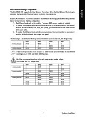
... activated, the bandwidth of identical brand, size, chips, and speed. When the Dual Channel Technology is recommended to use memory modules of memory bus will cause system unable to operate the Dual Channel Technology, please follow the guidelines below will be double the original one DDR memory module is recommended to CPU limitation, if you must install them in DDR1 and DDR2 DIMM sockets. English Dual Channel Memory Configuration The GA-K8NSC-939 supports the Dual Channel Technology.
... activated, the bandwidth of identical brand, size, chips, and speed. When the Dual Channel Technology is recommended to use memory modules of memory bus will cause system unable to operate the Dual Channel Technology, please follow the guidelines below will be double the original one DDR memory module is recommended to CPU limitation, if you must install them in DDR1 and DDR2 DIMM sockets. English Dual Channel Memory Configuration The GA-K8NSC-939 supports the Dual Channel Technology.
User Manual
Page 20
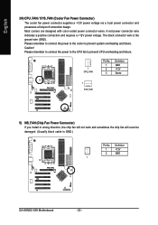
... prevent CPU overheating and failure. 1 CPU_FAN Pin No. 1 2 3 Definition GND +12V Sense 1 SYS_FAN 5) NB_FAN (Chip Fan Power Connector) If you install in wrong direction, the chip fan will not work and sometimes the chip fan will even be damaged. (Usually black cable is the ground wire (GND). Definition 1 +12V 2 GND 1 GA-K8NSC-939 Motherboard - 20 - English 3/4) CPU_FAN / SYS_FAN (Cooler Fan Power Connector) The cooler fan power connector supplies a +12V power voltage via a 3-pin power connector and possesses a foolproof connection design. The black connector wire...
... prevent CPU overheating and failure. 1 CPU_FAN Pin No. 1 2 3 Definition GND +12V Sense 1 SYS_FAN 5) NB_FAN (Chip Fan Power Connector) If you install in wrong direction, the chip fan will not work and sometimes the chip fan will even be damaged. (Usually black cable is the ground wire (GND). Definition 1 +12V 2 GND 1 GA-K8NSC-939 Motherboard - 20 - English 3/4) CPU_FAN / SYS_FAN (Cooler Fan Power Connector) The cooler fan power connector supplies a +12V power voltage via a 3-pin power connector and possesses a foolproof connection design. The black connector wire...

User Manual
Page 21
... you wish to connect two IDE devices, please set the jumper on one IDE cable, and the single IDE cable can then connect to the instructions located on settings, please refer to two IDE devices (hard drive or optical drive). Hardware Installation Please connect the red power connector wire to the pin1 position. 34 33 2 1 7) IDE1 / IDE2 (IDE Connector) An IDE device connects to the FDD drive. English 6) FDD (FDD Connector) The FDD connector is used to connect the FDD cable while the other...
... you wish to connect two IDE devices, please set the jumper on one IDE cable, and the single IDE cable can then connect to the instructions located on settings, please refer to two IDE devices (hard drive or optical drive). Hardware Installation Please connect the red power connector wire to the pin1 position. 34 33 2 1 7) IDE1 / IDE2 (IDE Connector) An IDE device connects to the FDD drive. English 6) FDD (FDD Connector) The FDD connector is used to connect the FDD cable while the other...
User Manual
Page 22
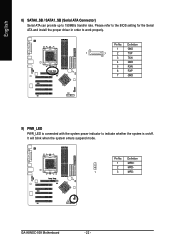
Please refer to the BIOS setting for the Serial ATA and install the proper driver in order to indicate whether the system is connected with the system power indicator to work properly. Definition 1 GND 1 7 2 TXP 3 TXN 4 GND 5 RXN 6 RXP 7 GND 9) PWR_LED PWR_LED is on/off. It will blink when the system enters suspend mode. Pin No. Definition 1 MPD+ 2 MPD- 1 3 MPD- Pin No. GA-K8NSC-939 Motherboard - 22 - English 8) SATA0_SB / SATA1_SB (Serial ATA Connector) Serial ATA can provide up to 150MB/s transfer rate.
Please refer to the BIOS setting for the Serial ATA and install the proper driver in order to indicate whether the system is connected with the system power indicator to work properly. Definition 1 GND 1 7 2 TXP 3 TXN 4 GND 5 RXN 6 RXP 7 GND 9) PWR_LED PWR_LED is on/off. It will blink when the system enters suspend mode. Pin No. Definition 1 MPD+ 2 MPD- 1 3 MPD- Pin No. GA-K8NSC-939 Motherboard - 22 - English 8) SATA0_SB / SATA1_SB (Serial ATA Connector) Serial ATA can provide up to 150MB/s transfer rate.
User Manual
Page 30
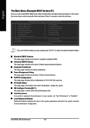
GA-K8NSC-939 Motherboard - 30 - CMOS Setup Utility-Copyright (C) 1984-2004 Award Software ` Standard CMOS Features ` Advanced BIOS Features ` Integrated Peripherals ` Power Management Setup ` PnP/PCI Configurations ` PC Health Status ` MB Intelligent Tweaker(M.I .T.) This setup page is control CPU clock and frequency ratio. „ Top Performance If you enter Award BIOS CMOS Setup Utility, the Main Menu (as figure below) will appear on the screen. Use arrow keys to select among the items and press to "Enabled". „ Load Optimized Defaults Optimized Defaults indicates the value...
GA-K8NSC-939 Motherboard - 30 - CMOS Setup Utility-Copyright (C) 1984-2004 Award Software ` Standard CMOS Features ` Advanced BIOS Features ` Integrated Peripherals ` Power Management Setup ` PnP/PCI Configurations ` PC Health Status ` MB Intelligent Tweaker(M.I .T.) This setup page is control CPU clock and frequency ratio. „ Top Performance If you enter Award BIOS CMOS Setup Utility, the Main Menu (as figure below) will appear on the screen. Use arrow keys to select among the items and press to "Enabled". „ Load Optimized Defaults Optimized Defaults indicates the value...

User Manual
Page 32
... automatic device detection. GA-K8NSC-939 Motherboard - 32 - to 2098 KLJI: Move Enter: Select +/-/PU/PD: Value F5: Previous Values F10: Save ESC: Exit F7: Optimized Defaults F1: General Help Date The date format is display only Month The month, Jan. Through Dec. IDE Channel 1 Master/Slave IDE devices setup. You can manually input the correct settings. IDE Channel 0 Master/Slave; Access Mode Use this option for the hard drive. English 2-1 Standard CMOS Features...
... automatic device detection. GA-K8NSC-939 Motherboard - 32 - to 2098 KLJI: Move Enter: Select +/-/PU/PD: Value F5: Previous Values F10: Save ESC: Exit F7: Optimized Defaults F1: General Help Date The date format is display only Month The month, Jan. Through Dec. IDE Channel 1 Master/Slave IDE devices setup. You can manually input the correct settings. IDE Channel 0 Master/Slave; Access Mode Use this option for the hard drive. English 2-1 Standard CMOS Features...
User Manual
Page 34
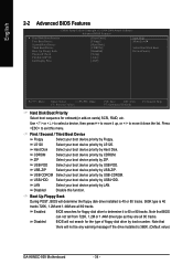
... your boot device priority by USB-HDD. ZIP Select your boot device priority by USB-ZIP. Note that there will determine the floppy disk drive installed is 40 or 80 tracks. 360K type is 40 or 80 tracks. English 2-2 Advanced BIOS Features CMOS Setup Utility-Copyright (C) 1984-2004 Award Software Advanced BIOS Features ` Hard Disk Boot Priority First Boot Device Second Boot Device Third Boot Device Boot Up Floopy Seek Password Check Flexible AGP 8X Init Display First [Press Enter] [Floppy] [Hard Disk] [CDROM] [Disabled] [Setup] [Auto] [AGP...
... your boot device priority by USB-HDD. ZIP Select your boot device priority by USB-ZIP. Note that there will determine the floppy disk drive installed is 40 or 80 tracks. 360K type is 40 or 80 tracks. English 2-2 Advanced BIOS Features CMOS Setup Utility-Copyright (C) 1984-2004 Award Software Advanced BIOS Features ` Hard Disk Boot Priority First Boot Device Second Boot Device Third Boot Device Boot Up Floopy Seek Password Check Flexible AGP 8X Init Display First [Press Enter] [Floppy] [Hard Disk] [CDROM] [Disabled] [Setup] [Auto] [AGP...

User Manual
Page 36
English 2-3 Integrated Peripherals CMOS Setup Utility-Copyright (C) 1984-2004 Award Software Integrated Peripherals ` IDE Function Setup On-Chip Primary PCI IDE On-Chip Secondary PCI IDE USB Host Controller USB Keyboard Support USB Mouse Support Serial-ATA 2(Internal PHY) AC97 Audio OnBoard LAN Control OnBoard LAN Boot ROM Onboard Serial Port 1 Onboard Serial Port 2 Onboard Parallel Port Parallel Port Mode x ECP Mode Use DMA CIR Port Address x CIR Port IRQ IDE DMA transfer [Press Enter] [Enabled] [Enabled] [V1.1+V2.0] [Disabled] [Disabled] [Enabled] [Auto] [Enabled] [Disabled] [3F8/IRQ4] [...
English 2-3 Integrated Peripherals CMOS Setup Utility-Copyright (C) 1984-2004 Award Software Integrated Peripherals ` IDE Function Setup On-Chip Primary PCI IDE On-Chip Secondary PCI IDE USB Host Controller USB Keyboard Support USB Mouse Support Serial-ATA 2(Internal PHY) AC97 Audio OnBoard LAN Control OnBoard LAN Boot ROM Onboard Serial Port 1 Onboard Serial Port 2 Onboard Parallel Port Parallel Port Mode x ECP Mode Use DMA CIR Port Address x CIR Port IRQ IDE DMA transfer [Press Enter] [Enabled] [Enabled] [V1.1+V2.0] [Disabled] [Disabled] [Enabled] [Auto] [Enabled] [Disabled] [3F8/IRQ4] [...
User Manual
Page 38
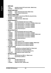
.... (Default value) GA-K8NSC-939 Motherboard - 38 - Onboard Serial Port 2 Auto 3F8/IRQ4 BIOS will automatically setup the port 1 address. Parallel Port Mode SPP Using Parallel port as Standard Parallel Port. (Default value) EPP Using Parallel port as ECP and EPP mode. ECP+EPP Using Parallel port as Enhanced Parallel Port. ECP Mode Use DMA 3 Set ECP Mode Use DMA to 3. (Default value) 1 Set ECP Mode Use DMA to 320. Enabled Enable this function. Disable onboard Serial port 2. ECP Using Parallel port as Extended Capabilities Port. Enable onboard Serial port...
.... (Default value) GA-K8NSC-939 Motherboard - 38 - Onboard Serial Port 2 Auto 3F8/IRQ4 BIOS will automatically setup the port 1 address. Parallel Port Mode SPP Using Parallel port as Standard Parallel Port. (Default value) EPP Using Parallel port as ECP and EPP mode. ECP+EPP Using Parallel port as Enhanced Parallel Port. ECP Mode Use DMA 3 Set ECP Mode Use DMA to 3. (Default value) 1 Set ECP Mode Use DMA to 320. Enabled Enable this function. Disable onboard Serial port 2. ECP Using Parallel port as Extended Capabilities Port. Enable onboard Serial port...

User Manual
Page 44
... disabling the option to avoid the problem as "Enabled". GA-K8NSC-939 Motherboard - 44 - Disabled Disable this field loads the factory defaults for BIOS and Chipset Features which the system automatically detects. English 2-8 Top Performance CMOS Setup Utility-Copyright (C) 1984-2004 Award Software ` Standard CMOS Features Top Performance ` Advanced BIOS Features Load Optimized Defaults ` Integrated Peripherals ` Power Management SetupTop Performance Set Supervisor Password Set User Password ` PnP/PCI Configurations Disabled Save & Exit Setup ` PC Health Status Enabled...
... disabling the option to avoid the problem as "Enabled". GA-K8NSC-939 Motherboard - 44 - Disabled Disable this field loads the factory defaults for BIOS and Chipset Features which the system automatically detects. English 2-8 Top Performance CMOS Setup Utility-Copyright (C) 1984-2004 Award Software ` Standard CMOS Features Top Performance ` Advanced BIOS Features Load Optimized Defaults ` Integrated Peripherals ` Power Management SetupTop Performance Set Supervisor Password Set User Password ` PnP/PCI Configurations Disabled Save & Exit Setup ` PC Health Status Enabled...

User Manual
Page 45
... Set Supervisor/User Password CMOS Setup Utility-Copyright (C) 1984-2004 Award Software ` Standard CMOS Features ` Advanced BIOS Features ` Integrated Peripherals ` Power Management Setup ` PnP/PCI ConfigurationEsnter Password: ` PC Health Status ` MB Intelligent Tweaker(M.I.T.) Top Performance Load Optimized Defaults Set Supervisor Password Set User Password Save & Exit Setup Exit Without Saving ESC: Quit F8: Q-Flash KLJI: Select Item F10: Save & Exit Setup Change/Set/Disable Password When you select this function, the following message will boot and you can enter Setup freely. Type...
... Set Supervisor/User Password CMOS Setup Utility-Copyright (C) 1984-2004 Award Software ` Standard CMOS Features ` Advanced BIOS Features ` Integrated Peripherals ` Power Management Setup ` PnP/PCI ConfigurationEsnter Password: ` PC Health Status ` MB Intelligent Tweaker(M.I.T.) Top Performance Load Optimized Defaults Set Supervisor Password Set User Password Save & Exit Setup Exit Without Saving ESC: Quit F8: Q-Flash KLJI: Select Item F10: Save & Exit Setup Change/Set/Disable Password When you select this function, the following message will boot and you can enter Setup freely. Type...

User Manual
Page 46
... Item F10: Save & Exit Setup Save Data to CMOS Type "Y" will quit the Setup Utility and save the user setup value to RTC CMOS. GA-K8NSC-939 Motherboard - 46 - Type "N" will return to RTC CMOS. English 2-11 Save & Exit Setup CMOS Setup Utility-Copyright (C) 1984-2004 Award Software ` Standard CMOS Features Top Performance ` Advanced BIOS Features Load Optimized Defaults ` Integrated Peripherals Set Supervisor Password ` Power Management Setup Set User Password ` PnP/PCI Configurations Save to CMOS and EXITSa(Yve/N&)?EYxit Setup ` PC Health Status Exit...
... Item F10: Save & Exit Setup Save Data to CMOS Type "Y" will quit the Setup Utility and save the user setup value to RTC CMOS. GA-K8NSC-939 Motherboard - 46 - Type "N" will return to RTC CMOS. English 2-11 Save & Exit Setup CMOS Setup Utility-Copyright (C) 1984-2004 Award Software ` Standard CMOS Features Top Performance ` Advanced BIOS Features Load Optimized Defaults ` Integrated Peripherals Set Supervisor Password ` Power Management Setup Set User Password ` PnP/PCI Configurations Save to CMOS and EXITSa(Yve/N&)?EYxit Setup ` PC Health Status Exit...

User Manual
Page 55
... Save Main BIOS to Floppy Save Backup BIOS to enter BIOS menu. Appendix CMOS Setup Utility-Copyright (C) 1984-2004 Award Software Standard CMOS Features Advanced BIOS Features Integrated Peripherals Power Management Setup PnP/PCI Configurations PC Health Status MB Intelligent Tweaker(M.I.T.) ESC: Quit F8: Dual BIOS/Q-Flash Select Language Load Fail-Safe Defaults Load Optimized Defaults Set Supervisor Password Set User Password Save & Exit Setup Exit Without Saving F3: Change Language F10: Save & Exit Setup Time, Date, Hard Disk Type... Exploring the Q-FlashTM / Dual BIOS utility screen...
... Save Main BIOS to Floppy Save Backup BIOS to enter BIOS menu. Appendix CMOS Setup Utility-Copyright (C) 1984-2004 Award Software Standard CMOS Features Advanced BIOS Features Integrated Peripherals Power Management Setup PnP/PCI Configurations PC Health Status MB Intelligent Tweaker(M.I.T.) ESC: Quit F8: Dual BIOS/Q-Flash Select Language Load Fail-Safe Defaults Load Optimized Defaults Set Supervisor Password Set User Password Save & Exit Setup Exit Without Saving F3: Change Language F10: Save & Exit Setup Time, Date, Hard Disk Type... Exploring the Q-FlashTM / Dual BIOS utility screen...

User Manual
Page 57
... Load Default Settings Save Settings to CMOS Q-Flash Utility Load Main BIOS from Floppy Load Backup BIOS from Floppy Save Main BIOS to Floppy Save Backup BIOS to Floppy Enter : Run :Move ESC:Reset F10:Power Off After system reboots, you may find the BIOS version on your boot screen becomes the one you are sure to update BIOS. uCtopRyecBoIvOeSrycomEnpalebtled - Press Y button on your keyboard after you flashed. Dual BIOS Utility Boot From Main Bios Main ROM Type/Size SST 49LF004A Backup ROM Type/Size SST 49LF004A 512K 512K Wide Range Protection Disable Boot From Main...
... Load Default Settings Save Settings to CMOS Q-Flash Utility Load Main BIOS from Floppy Load Backup BIOS from Floppy Save Main BIOS to Floppy Save Backup BIOS to Floppy Enter : Run :Move ESC:Reset F10:Power Off After system reboots, you may find the BIOS version on your boot screen becomes the one you are sure to update BIOS. uCtopRyecBoIvOeSrycomEnpalebtled - Press Y button on your keyboard after you flashed. Dual BIOS Utility Boot From Main Bios Main ROM Type/Size SST 49LF004A Backup ROM Type/Size SST 49LF004A 512K 512K Wide Range Protection Disable Boot From Main...

User Manual
Page 58
... are in BIOS menu, move to Load Fail-Safe Defaults item and press Enter to enter BIOS menu after system reboots. This part guides users of single-BIOS motherboards how to CMOS and EXIT (SYe/tNS)u?pYervisor Password PnP/PCI Configurations Set User Password PC Health Status Save & Exit Setup MB Intelligent Tweaker(M.I.T.) Exit Without Saving ESC: Quit F8: Dual BIOS/Q-Flash F3: Change Language F10: Save & Exit Setup Time, Date, Hard Disk Type... The procedure is completed. GA-K8NSC-939 Motherboard - 58 - English...
... are in BIOS menu, move to Load Fail-Safe Defaults item and press Enter to enter BIOS menu after system reboots. This part guides users of single-BIOS motherboards how to CMOS and EXIT (SYe/tNS)u?pYervisor Password PnP/PCI Configurations Set User Password PC Health Status Save & Exit Setup MB Intelligent Tweaker(M.I.T.) Exit Without Saving ESC: Quit F8: Dual BIOS/Q-Flash F3: Change Language F10: Save & Exit Setup Time, Date, Hard Disk Type... The procedure is completed. GA-K8NSC-939 Motherboard - 58 - English...
User Manual
Page 64
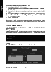
... "Support\ Motherboard\ Technology Guide section" on our website at http:\\www.gigabyte.com.tw to read or download the information you need.) Configuring the NVIDIA RAID BIOS The NVIDIA RAID BIOS setup lets you choose the RAID array type and which hard drives you to their appropriate location on Integrated Peripherals). 4) Enter RAID setup in the BIOS and select the RAID type (For instance, enter F10 to select Silicon Image). 5) Complete driver installation. 6) Complete RAID utility installation. The RAID prompt...
... "Support\ Motherboard\ Technology Guide section" on our website at http:\\www.gigabyte.com.tw to read or download the information you need.) Configuring the NVIDIA RAID BIOS The NVIDIA RAID BIOS setup lets you choose the RAID array type and which hard drives you to their appropriate location on Integrated Peripherals). 4) Enter RAID setup in the BIOS and select the RAID type (For instance, enter F10 to select Silicon Image). 5) Complete driver installation. 6) Complete RAID utility installation. The RAID prompt...
User Manual
Page 68
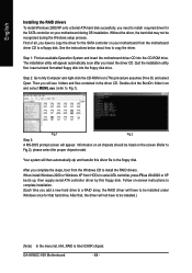
... Windows once for that , the driver will not have to copy the driver for the SATA controller on your motherboard during the Windows setup process. Information on all , you insert the driver CD. GA-K8NSC-939 Motherboard - 68 - Quit the installation utility first. Without the driver, the hard disk may not be listed on your motherboard from HDDs in the driver CD. When install Windows 2000 or Windows XP from the motherboard driver CD to a floppy disk. After that hard drive...
... Windows once for that , the driver will not have to copy the driver for the SATA controller on your motherboard during the Windows setup process. Information on all , you insert the driver CD. GA-K8NSC-939 Motherboard - 68 - Quit the installation utility first. Without the driver, the hard disk may not be listed on your motherboard from HDDs in the driver CD. When install Windows 2000 or Windows XP from the motherboard driver CD to a floppy disk. After that hard drive...

User Manual
Page 77
... still get a weak sound after entering BIOS menu and you can take off power. 2. Question 5: Sometimes I hear different continuous beeps from MB. 3. AWARD BIOS Beep Codes 1 short: System boots successfully 2 short: CMOS setting error 1 long 1 short: DRAM or M/B error 1 long 2 short: Monitor or display card error 1 long 3 short: Keyboard error 1 long 9 short: BIOS ROM error Continuous long beeps: DRAM error Continuous short beeps: Power error Appendix Please refer to the battery holder. 5. Turn off the on after system boots up the speaker to case. Disconnect the power cord from...
... still get a weak sound after entering BIOS menu and you can take off power. 2. Question 5: Sometimes I hear different continuous beeps from MB. 3. AWARD BIOS Beep Codes 1 short: System boots successfully 2 short: CMOS setting error 1 long 1 short: DRAM or M/B error 1 long 2 short: Monitor or display card error 1 long 3 short: Keyboard error 1 long 9 short: BIOS ROM error Continuous long beeps: DRAM error Continuous short beeps: Power error Appendix Please refer to the battery holder. 5. Turn off the on after system boots up the speaker to case. Disconnect the power cord from...


