User Manual
Page 4
Table of Contents GA-K8NF-9 Motherboard Layout 6 Block Diagram ...7 Chapter 1 Hardware Installation 9 1-1 Considerations Prior to Installation 9 1-2 Feature Summary 10 1-3 Installation of the CPU and Fan Heat Sink 12 ... of Memory 14 1-5 Installation of Expansion Cards 16 1-6 I/O Back Panel Introduction 17 1-7 Connectors Introduction 18 Chapter 2 BIOS Setup 29 The Main Menu (For example: BIOS Ver. : F9 30 2-1 Standard CMOS Features 32 2-2 Advanced BIOS Features 34 2-3 IntegratedPeripherals 35 2-4 Power Management Setup 39 2-5 PnP/PCI Configurations 40 2-6 PC Health Status 41 2-7 ...
Table of Contents GA-K8NF-9 Motherboard Layout 6 Block Diagram ...7 Chapter 1 Hardware Installation 9 1-1 Considerations Prior to Installation 9 1-2 Feature Summary 10 1-3 Installation of the CPU and Fan Heat Sink 12 ... of Memory 14 1-5 Installation of Expansion Cards 16 1-6 I/O Back Panel Introduction 17 1-7 Connectors Introduction 18 Chapter 2 BIOS Setup 29 The Main Menu (For example: BIOS Ver. : F9 30 2-1 Standard CMOS Features 32 2-2 Advanced BIOS Features 34 2-3 IntegratedPeripherals 35 2-4 Power Management Setup 39 2-5 PnP/PCI Configurations 40 2-6 PC Health Status 41 2-7 ...

User Manual
Page 5
Chapter 3 Drivers Installation 47 3-1 Install Chipset Drivers 47 3-2 SoftwareApplication 48 3-3 Software Information 48 3-4 Hardware Information 49 3-5 Contact Us ...49 Chapter 4 Appendix 51 4-1 Unique Software Utilities 51 4-1-1 EasyTune 5 Introduction 51 4-1-2 Xpress Recovery2 Introduction 52 4-1-3 Flash BIOS Method Introduction 54 4-1-4 Serial ATA BIOS Setting Utility Introduction 63 4-1-5 2- / 4- / 6- / 8- Channel Audio Function Introduction 69 4-2 Troubleshooting 75 - 5 -
Chapter 3 Drivers Installation 47 3-1 Install Chipset Drivers 47 3-2 SoftwareApplication 48 3-3 Software Information 48 3-4 Hardware Information 49 3-5 Contact Us ...49 Chapter 4 Appendix 51 4-1 Unique Software Utilities 51 4-1-1 EasyTune 5 Introduction 51 4-1-2 Xpress Recovery2 Introduction 52 4-1-3 Flash BIOS Method Introduction 54 4-1-4 Serial ATA BIOS Setting Utility Introduction 63 4-1-5 2- / 4- / 6- / 8- Channel Audio Function Introduction 69 4-2 Troubleshooting 75 - 5 -

User Manual
Page 11
supports data transfer rate of licensed AWARD BIOS Supports Q-Flash Supports @BIOS Supports EasyTune (Note 2) Over Voltage via BIOS (CPU/ DDR/ HT-Link/ Core Power) ATX form factor; 30.5cm x 24.4cm (Note 2) EasyTune functions may vary depending on ...to 150 MB/s - English I/O Control Š Hardware Monitor Š Š Š Š Š Š Onboard SATA RAID Š Š BIOS Š Š Additional Features Š Š Overclocking Š Form Factor Š IT8712F System voltage detection CPU temperature detection CPU / System fan speed detection ...
supports data transfer rate of licensed AWARD BIOS Supports Q-Flash Supports @BIOS Supports EasyTune (Note 2) Over Voltage via BIOS (CPU/ DDR/ HT-Link/ Core Power) ATX form factor; 30.5cm x 24.4cm (Note 2) EasyTune functions may vary depending on ...to 150 MB/s - English I/O Control Š Hardware Monitor Š Š Š Š Š Š Onboard SATA RAID Š Š BIOS Š Š Additional Features Š Š Overclocking Š Form Factor Š IT8712F System voltage detection CPU temperature detection CPU / System fan speed detection ...

User Manual
Page 14
... power is supported by the motherboard. A memory module can only fit in only one direction. Insert the DIMM memory module vertically into the DIMM socket. GA-K8NF-9 Motherboard - 14 - Reverse the installation steps when you are designed so that the memory used . 2. Then push it down. Notch DDR Fig.1 The DIMM socket... make sure that they can differ with the following conditions: 1. If you wish to lock the DIMM module. The motherboard supports DDR memory modules, whereby BIOS will automatically detect memory capacity and specifications.
... power is supported by the motherboard. A memory module can only fit in only one direction. Insert the DIMM memory module vertically into the DIMM socket. GA-K8NF-9 Motherboard - 14 - Reverse the installation steps when you are designed so that the memory used . 2. Then push it down. Notch DDR Fig.1 The DIMM socket... make sure that they can differ with the following conditions: 1. If you wish to lock the DIMM module. The motherboard supports DDR memory modules, whereby BIOS will automatically detect memory capacity and specifications.

User Manual
Page 15
...memory module is for BIOS to use dual channel memory and for Dual Channel Technology combination: (DS: Double Side, SS: Single Side) 2 memory modules 4 memory modules DDR 1 DS/SS X DS/SS DDR 2 DS/SS X DS/SS DDR 3 X DS/SS DS/SS DDR 4 X DS/SS DS/SS The GA-K8NF-9 doesn't support ... detect all the DDR memory modules. If two DDR memory modules are installed, please use memory of Memory Bus will not boot. - 15 - Hardware Installation GA-K8NF-9 includes 4 DIMM sockets, and each Channel has two DIMM sockets as following: Channel A : DDR 1, DDR 3 Channel B : DDR 2, DDR 4 If you want ...
...memory module is for BIOS to use dual channel memory and for Dual Channel Technology combination: (DS: Double Side, SS: Single Side) 2 memory modules 4 memory modules DDR 1 DS/SS X DS/SS DDR 2 DS/SS X DS/SS DDR 3 X DS/SS DS/SS DDR 4 X DS/SS DS/SS The GA-K8NF-9 doesn't support ... detect all the DDR memory modules. If two DDR memory modules are installed, please use memory of Memory Bus will not boot. - 15 - Hardware Installation GA-K8NF-9 includes 4 DIMM sockets, and each Channel has two DIMM sockets as following: Channel A : DDR 1, DDR 3 Channel B : DDR 2, DDR 4 If you want ...

User Manual
Page 16
Power on the computer, if necessary, setup BIOS utility of expansion card from the operating system. Please align the VGA card to install/uninstall the VGA card. English 1-5 Installation of Expansion ...in motherboard. 4. Install related driver from BIOS. 8. Press the expansion card firmly into the computer. 2. Replace your computer's chassis cover, screws and slot bracket from the computer. 3. Read the related expansion card's instruction document before install the expansion card into expansion slot in the slot. 5. GA-K8NF-9 Motherboard - 16 - Remove your computer's...
Power on the computer, if necessary, setup BIOS utility of expansion card from the operating system. Please align the VGA card to install/uninstall the VGA card. English 1-5 Installation of Expansion ...in motherboard. 4. Install related driver from BIOS. 8. Press the expansion card firmly into the computer. 2. Replace your computer's chassis cover, screws and slot bracket from the computer. 3. Read the related expansion card's instruction document before install the expansion card into expansion slot in the slot. 5. GA-K8NF-9 Motherboard - 16 - Remove your computer's...
User Manual
Page 22
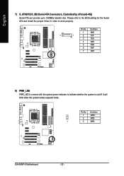
Pin No. Definition 1 GND 7 1 2 TXP 3 TXN 4 GND 5 RXN 6 RXP 7 GND 8) PWR_LED PWR_LED is connect with the system power indicator to work properly. Please refer to the BIOS setting for the Serial ATA and install the proper driver in order to indicate whether the system is on/off. It will blink when the system enters suspend mode. GA-K8NF-9 Motherboard - 22 - Definition 1 MPD+ 2 MPD- 1 3 MPD- Pin No. English 7) S_ATA0/1/2/3_SB (Serial ATA Connectors, Controlled by nForce4(-4X)) Serial ATA can provide up to 150MB/s transfer rate.
Pin No. Definition 1 GND 7 1 2 TXP 3 TXN 4 GND 5 RXN 6 RXP 7 GND 8) PWR_LED PWR_LED is connect with the system power indicator to work properly. Please refer to the BIOS setting for the Serial ATA and install the proper driver in order to indicate whether the system is on/off. It will blink when the system enters suspend mode. GA-K8NF-9 Motherboard - 22 - Definition 1 MPD+ 2 MPD- 1 3 MPD- Pin No. English 7) S_ATA0/1/2/3_SB (Serial ATA Connectors, Controlled by nForce4(-4X)) Serial ATA can provide up to 150MB/s transfer rate.
User Manual
Page 29
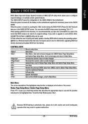
When the power is turned off, the battery on , pushing the button during the BIOS POST (Power-On Self Test) will take you to a new BIOS, either GIGABYTE's Q-Flash or @BIOS utility can enter the BIOS setup screen by pressing "Ctrl + F1". When setting up a small help , only for the ...highlighted item. CONTROL KEYS Move to activate certain system features. Quit and not save the current BIOS to a disk in the...
When the power is turned off, the battery on , pushing the button during the BIOS POST (Power-On Self Test) will take you to a new BIOS, either GIGABYTE's Q-Flash or @BIOS utility can enter the BIOS setup screen by pressing "Ctrl + F1". When setting up a small help , only for the ...highlighted item. CONTROL KEYS Move to activate certain system features. Quit and not save the current BIOS to a disk in the...
User Manual
Page 30
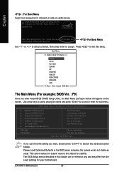
..." to exit this chapter are for reference only and may differ from the exact settings for stability. Award Modular BIOS v6.00PG, An Energy Star Ally Copyright (C) 1984-2005, Award Software, Inc. GA-K8NF-9 F9 . . . . :BIOS Setup/Q-Flash, : Xpress Recovery2, For Boot Menu 10/27/2005-NF-CK804-6A61FG0AC-00 For Boot Menu Use...
..." to exit this chapter are for reference only and may differ from the exact settings for stability. Award Modular BIOS v6.00PG, An Energy Star Ally Copyright (C) 1984-2005, Award Software, Inc. GA-K8NF-9 F9 . . . . :BIOS Setup/Q-Flash, : Xpress Recovery2, For Boot Menu 10/27/2005-NF-CK804-6A61FG0AC-00 For Boot Menu Use...
User Manual
Page 31
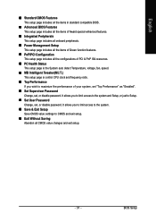
BIOS Setup It allows you wish to maximize the performance of Green function features. „ PnP/PCI Configuration This setup page includes all CMOS value changes .... „ Set User Password Change, set , or disable password. English „ Standard CMOS Features This setup page includes all the items in standard compatible BIOS. „ Advanced BIOS Features This setup page includes all the items of Award special enhanced features. „ Integrated Peripherals This setup page includes all onboard peripherals. „...
BIOS Setup It allows you wish to maximize the performance of Green function features. „ PnP/PCI Configuration This setup page includes all CMOS value changes .... „ Set User Password Change, set , or disable password. English „ Standard CMOS Features This setup page includes all the items in standard compatible BIOS. „ Advanced BIOS Features This setup page includes all the items of Award special enhanced features. „ Integrated Peripherals This setup page includes all onboard peripherals. „...
User Manual
Page 32
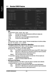
... automatic device detection. to Dec. to Sat. time clock. You can use one of three methods: • Auto • None Allows BIOS to automatically detect IDE devices during POST(default) • None Select this if no IDE devices are : CHS/LBA/Large/Auto(default:Auto)...the two methods: • Auto Allows BIOS to automatically detect IDE devices during POST. (Default value) Select this if no IDE devices are used and the system will skip the automatic • Manual detection step and allow for faster system start up . GA-K8NF-9 Motherboard - 32 - Jan. IDE ...
... automatic device detection. to Dec. to Sat. time clock. You can use one of three methods: • Auto • None Allows BIOS to automatically detect IDE devices during POST(default) • None Select this if no IDE devices are : CHS/LBA/Large/Auto(default:Auto)...the two methods: • Auto Allows BIOS to automatically detect IDE devices during POST. (Default value) Select this if no IDE devices are used and the system will skip the automatic • Manual detection step and allow for faster system start up . GA-K8NF-9 Motherboard - 32 - Jan. IDE ...

User Manual
Page 33
...drive B that may be prompted. Enter the appropriate option based on the outside drive casing. Hard drive information should be stopped. BIOS Setup Cylinder Number of cylinders Head Precomp Number of heads Write precomp Landing Zone Landing zone Sector Number of sectors Drive A / Drive... B The category identifies the types of currently installed hard drive. English Access Mode Use this information. Whenever the BIOS detects a non-fatal error the system will not stop for all other errors. All, But Keyboard The system boot will not ...
...drive B that may be prompted. Enter the appropriate option based on the outside drive casing. Hard drive information should be stopped. BIOS Setup Cylinder Number of cylinders Head Precomp Number of heads Write precomp Landing Zone Landing zone Sector Number of sectors Drive A / Drive... B The category identifies the types of currently installed hard drive. English Access Mode Use this information. Whenever the BIOS detects a non-fatal error the system will not stop for all other errors. All, But Keyboard The system boot will not ...
User Manual
Page 34
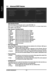
... by Hard Disk. USB-ZIP Select your boot device priority by USB-ZIP. LAN Select your boot device priority by LAN. Enabled BIOS searches for floppy disk drive to Setup page will not be denied if the correct password is 40 or 80 tracks. Note that ...track number. LS120 Select your boot device priority by LS120. Disabled Disable this menu. GA-K8NF-9 Motherboard - 34 - USB-FDD Select your boot device priority by USB-FDD. Boot Up Floppy Seek During POST, BIOS will be any warning message if the drive installed is 360K.(Default value) Password ...
... by Hard Disk. USB-ZIP Select your boot device priority by USB-ZIP. LAN Select your boot device priority by LAN. Enabled BIOS searches for floppy disk drive to Setup page will not be denied if the correct password is 40 or 80 tracks. Note that ...track number. LS120 Select your boot device priority by LS120. Disabled Disable this menu. GA-K8NF-9 Motherboard - 34 - USB-FDD Select your boot device priority by USB-FDD. Boot Up Floppy Seek During POST, BIOS will be any warning message if the drive installed is 360K.(Default value) Password ...
User Manual
Page 35
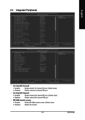
... ESC: Exit F7: Optimized Defaults On-Chip IDE Channel0 Enabled Disabled Enable onboard 1st channel IDE port. (Default value) Disable onboard 1st channel IDE port. BIOS Setup On-Chip IDE Channel1 Enabled Disabled Enable onboard 2nd channel IDE port. (Default value) Disable onboard 2nd channel IDE port.
... ESC: Exit F7: Optimized Defaults On-Chip IDE Channel0 Enabled Disabled Enable onboard 1st channel IDE port. (Default value) Disable onboard 1st channel IDE port. BIOS Setup On-Chip IDE Channel1 Enabled Disabled Enable onboard 2nd channel IDE port. (Default value) Disable onboard 2nd channel IDE port.

User Manual
Page 37
...SATA0 or SATA1 connector , please set "NV SATA1/NV SATA 2 class code" from 0101 to 0104. Onboard Serial Port 1 Auto 3F8/IRQ4 BIOS will automatically setup the IrDA port address. Disable onboard IrDA port . AC97 Audio Auto Enable onboard AC'97 audio function. (Default value) Disabled ...Memory(640K)Set USB memory type to base memory(640K). on the RAID drive. Disable onboard Serial port 1. Onboard IrDA Port Auto 3F8/IRQ4 BIOS will automatically setup the port 1 address. Enable onboard Serial port 1 and address is 3F8/IRQ4. (Default value) 2F8/IRQ3 3E8/IRQ4 Enable...
...SATA0 or SATA1 connector , please set "NV SATA1/NV SATA 2 class code" from 0101 to 0104. Onboard Serial Port 1 Auto 3F8/IRQ4 BIOS will automatically setup the IrDA port address. Disable onboard IrDA port . AC97 Audio Auto Enable onboard AC'97 audio function. (Default value) Disabled ...Memory(640K)Set USB memory type to base memory(640K). on the RAID drive. Disable onboard Serial port 1. Onboard IrDA Port Auto 3F8/IRQ4 BIOS will automatically setup the port 1 address. Enable onboard Serial port 1 and address is 3F8/IRQ4. (Default value) 2F8/IRQ3 3E8/IRQ4 Enable...
User Manual
Page 39
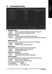
... Up This feature requires an ATX power supply that provides at least 1A on function. Enable PME as wake up system from any suspend state. BIOS Setup Disabled Disable Modem Ring on function. (Default value) Enabled Enable Modem Ring on the 5VSB lead. Power-On by Alarm You can awake the...
... Up This feature requires an ATX power supply that provides at least 1A on function. Enable PME as wake up system from any suspend state. BIOS Setup Disabled Disable Modem Ring on function. (Default value) Enabled Enable Modem Ring on the 5VSB lead. Power-On by Alarm You can awake the...

User Manual
Page 41
... run at the FAQ section on the CPU you install. Whether the CPU Smart FAN Control function is enabled, CPU fan will depend on GIGABYTE's website. - 41 - For more detailed information please check at different speed depending on their requirements. (Note) The CPU fan runs at...(Default value) CPU FAN Fail Warning Disabled Disable CPU fan fail warning function. (Default value) Enabled Enable CPU fan fail warning function. BIOS Setup Users can adjust the fan speed with Easy Tune based on CPU temperature. English 2-6 PC Health Status CMOS Setup Utility-Copyright (C) ...
... run at the FAQ section on the CPU you install. Whether the CPU Smart FAN Control function is enabled, CPU fan will depend on GIGABYTE's website. - 41 - For more detailed information please check at different speed depending on their requirements. (Note) The CPU fan runs at...(Default value) CPU FAN Fail Warning Disabled Disable CPU fan fail warning function. (Default value) Enabled Enable CPU fan fail warning function. BIOS Setup Users can adjust the fan speed with Easy Tune based on CPU temperature. English 2-6 PC Health Status CMOS Setup Utility-Copyright (C) ...

User Manual
Page 43
... to Center Spread. (Default value) PCIE Clock 100Mhz ~ 150Mhz Set PCI-E clock from x4 800Mhz to Turbo. Current DDR speed Displays the current DDR speed. BIOS Setup English 2-7 MB Intelligent Tweaker(M.I.T.) CMOS Setup Utility-Copyright (C) 1984-2004 Award Software MB Intelligent Tweaker(M.I.T.) HT Frequency ratio CPU Frequency K8 CPU Clock Ratio...
... to Center Spread. (Default value) PCIE Clock 100Mhz ~ 150Mhz Set PCI-E clock from x4 800Mhz to Turbo. Current DDR speed Displays the current DDR speed. BIOS Setup English 2-7 MB Intelligent Tweaker(M.I.T.) CMOS Setup Utility-Copyright (C) 1984-2004 Award Software MB Intelligent Tweaker(M.I.T.) HT Frequency ratio CPU Frequency K8 CPU Clock Ratio...
User Manual
Page 44
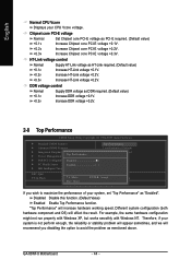
...system is not perform enough, the reliability or stability problem will appear sometimes, and we will increase hardware working speed. GA-K8NF-9 Motherboard - 44 - Chipset core PCI-E voltage Normal +0.1v Set Chipset core PCI-E voltage as HT-Link required. ... voltage +0.2V. 2-8 Top Performance CMOS Setup Utility-Copyright (C) 1984-2005 Award Software ` Standard CMOS Features Top Performance ` Advanced BIOS Features Load Optimized Defaults ` Integrated Peripherals ` Power Management SetuTpop Performance Set Supervisor Password Set User Password ` PnP/PCI ConfigurationsDisabled Save ...
...system is not perform enough, the reliability or stability problem will appear sometimes, and we will increase hardware working speed. GA-K8NF-9 Motherboard - 44 - Chipset core PCI-E voltage Normal +0.1v Set Chipset core PCI-E voltage as HT-Link required. ... voltage +0.2V. 2-8 Top Performance CMOS Setup Utility-Copyright (C) 1984-2005 Award Software ` Standard CMOS Features Top Performance ` Advanced BIOS Features Load Optimized Defaults ` Integrated Peripherals ` Power Management SetuTpop Performance Set Supervisor Password Set User Password ` PnP/PCI ConfigurationsDisabled Save ...

User Manual
Page 45
... English 2-9 Load Optimized Defaults CMOS Setup Utility-Copyright (C) 1984-2004 Award Software ` Standard CMOS Features Top Performance ` Advanced BIOS Features Load Optimized Defaults ` Integrated Peripherals Set Supervisor Password ` Power Management Setup Set User Password ` PnP/PCI Configurations Load ... Q-Flash KLJI: Select Item F10: Save & Exit Setup Load Optimized Defaults Selecting this field loads the factory defaults for BIOS and Chipset Features which the system automatically detects. 2-10 Set Supervisor/User Password CMOS Setup Utility-Copyright (C) 1984-2004 Award...
... English 2-9 Load Optimized Defaults CMOS Setup Utility-Copyright (C) 1984-2004 Award Software ` Standard CMOS Features Top Performance ` Advanced BIOS Features Load Optimized Defaults ` Integrated Peripherals Set Supervisor Password ` Power Management Setup Set User Password ` PnP/PCI Configurations Load ... Q-Flash KLJI: Select Item F10: Save & Exit Setup Load Optimized Defaults Selecting this field loads the factory defaults for BIOS and Chipset Features which the system automatically detects. 2-10 Set Supervisor/User Password CMOS Setup Utility-Copyright (C) 1984-2004 Award...


