Manual
Page 3
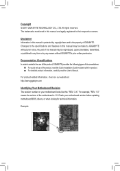
...In order to assist in this manual are legally registered to the specifications and features in this manual may be made by GIGABYTE without GIGABYTE's prior written permission. Check your motherboard looks like this manual is protected by any form or by copyright laws and is... Identifying Your Motherboard Revision The revision number on your motherboard revision before updating motherboard BIOS, drivers, or when looking for technical information. Example: No part of this product, GIGABYTE provides the following types of documentations: For quick set-up of the product, ...
...In order to assist in this manual are legally registered to the specifications and features in this manual may be made by GIGABYTE without GIGABYTE's prior written permission. Check your motherboard looks like this manual is protected by any form or by copyright laws and is... Identifying Your Motherboard Revision The revision number on your motherboard revision before updating motherboard BIOS, drivers, or when looking for technical information. Example: No part of this product, GIGABYTE provides the following types of documentations: For quick set-up of the product, ...

Manual
Page 4
Table of Contents Box Contents...6 Optional Items...6 GA-H67A-UD3H-B3 Motherboard Layout 7 GA-H67A-UD3H-B3 Motherboard Block Diagram 8 Chapter 1 Hardware Installation 9 1-1 Installation Precautions 9 1-2 Product Specifications 10 1-3 Installing the CPU and CPU ... an Expansion Card 18 1-6 Back Panel Connectors 19 1-7 Internal Connectors 22 Chapter 2 BIOS Setup 31 2-1 Startup Screen 32 2-2 The Main Menu 33 2-3 MB Intelligent Tweaker(M.I.T 35 2-4 Standard CMOS Features 43 2-5 Advanced BIOS Features 45 2-6 Integrated Peripherals 47 2-7 Power Management Setup 50 2-8 PC Health Status ...
Table of Contents Box Contents...6 Optional Items...6 GA-H67A-UD3H-B3 Motherboard Layout 7 GA-H67A-UD3H-B3 Motherboard Block Diagram 8 Chapter 1 Hardware Installation 9 1-1 Installation Precautions 9 1-2 Product Specifications 10 1-3 Installing the CPU and CPU ... an Expansion Card 18 1-6 Back Panel Connectors 19 1-7 Internal Connectors 22 Chapter 2 BIOS Setup 31 2-1 Startup Screen 32 2-2 The Main Menu 33 2-3 MB Intelligent Tweaker(M.I.T 35 2-4 Standard CMOS Features 43 2-5 Advanced BIOS Features 45 2-6 Integrated Peripherals 47 2-7 Power Management Setup 50 2-8 PC Health Status ...

Manual
Page 5
... 58 3-4 Contact...59 3-5 System...59 3-6 Download Center 60 3-7 New Utilities...60 Chapter 4 Unique Features 61 4-1 Xpress Recovery2 61 4-2 BIOS Update Utilities 64 4-2-1 Updating the BIOS with the Q-Flash Utility 64 4-2-2 Updating the BIOS with the @BIOS Utility 67 4-3 EasyTune 6...68 4-4 Dynamic Energy Saver™ 2 69 4-5 Q-Share...71 4-6 Smart 6™ ...72 4-7 Auto Green...76 4-8 eXtreme...
... 58 3-4 Contact...59 3-5 System...59 3-6 Download Center 60 3-7 New Utilities...60 Chapter 4 Unique Features 61 4-1 Xpress Recovery2 61 4-2 BIOS Update Utilities 64 4-2-1 Updating the BIOS with the Q-Flash Utility 64 4-2-2 Updating the BIOS with the @BIOS Utility 67 4-3 EasyTune 6...68 4-4 Dynamic Energy Saver™ 2 69 4-5 Q-Share...71 4-6 Smart 6™ ...72 4-7 Auto Green...76 4-8 eXtreme...

Manual
Page 8
GA-H67A-UD3H-B3 Motherboard Block Diagram 1 PCI Express x16 PCIe CLK (100 MHz) LGA1155 CPU CPU CLK+/- (100 MHz) DDR3 1333/1066/800 MHz Dual Channel Memory PCI ... RTL8111E iTE IT8892 Bridge 1 PCI Express x1 RJ45 LAN PCI Bus TSB43AB23 Intel® H67 CODEC DMI Interface FDI Interface DisplayPort HDMI DVI-D D-Sub Dual BIOS 2 SATA 6Gb/s 4 SATA 3Gb/s 14 USB 2.0/1.1 LPC Bus iTE IT8728 COM PS/2 KB/Mouse 3 IEEE 1394a Surround Speaker Out Center/Subwoofer Speaker Out Side Speaker...
GA-H67A-UD3H-B3 Motherboard Block Diagram 1 PCI Express x16 PCIe CLK (100 MHz) LGA1155 CPU CPU CLK+/- (100 MHz) DDR3 1333/1066/800 MHz Dual Channel Memory PCI ... RTL8111E iTE IT8892 Bridge 1 PCI Express x1 RJ45 LAN PCI Bus TSB43AB23 Intel® H67 CODEC DMI Interface FDI Interface DisplayPort HDMI DVI-D D-Sub Dual BIOS 2 SATA 6Gb/s 4 SATA 3Gb/s 14 USB 2.0/1.1 LPC Bus iTE IT8728 COM PS/2 KB/Mouse 3 IEEE 1394a Surround Speaker Out Center/Subwoofer Speaker Out Side Speaker...

Manual
Page 12
... cooler you install. 2 x 32 Mbit flash Use of licensed AWARD BIOS Support for DualBIOS™ PnP 1.0a, DMI 2.0, SM BIOS 2.4, ACPI 1.0b Support for @BIOS Support for Q-Flash Support for Xpress BIOS Rescue Support for Download Center Support for Xpress Install Support for Xpress Recovery2... Support for Microsoft® Windows® 7/Vista/XP Form Factor w ATX Form Factor; 30.5cm x 24.4cm * GIGABYTE reserves the ...
... cooler you install. 2 x 32 Mbit flash Use of licensed AWARD BIOS Support for DualBIOS™ PnP 1.0a, DMI 2.0, SM BIOS 2.4, ACPI 1.0b Support for @BIOS Support for Q-Flash Support for Xpress BIOS Rescue Support for Download Center Support for Xpress Install Support for Xpress Recovery2... Support for Microsoft® Windows® 7/Vista/XP Form Factor w ATX Form Factor; 30.5cm x 24.4cm * GIGABYTE reserves the ...

Manual
Page 16
...DS/SS - - - - 1-4 Installing the Memory Read the following guidelines before installing the memory in only one DDR3 memory module is installed, the BIOS will double the original memory bandwidth. Dual Channel mode cannot be installed in Dual Channel mode. 1. A memory module can be enabled if only one ... Dual Channel memory mode will automatically detect the specifications and capacity of the same capacity, brand, speed, and chips be used . (Go to GIGABYTE's website for optimum performance. DS/SS Four Modules DS/SS DS/SS DS/SS DS/SS (SS=Single-Sided, DS=Double-Sided, "- -"=...
...DS/SS - - - - 1-4 Installing the Memory Read the following guidelines before installing the memory in only one DDR3 memory module is installed, the BIOS will double the original memory bandwidth. Dual Channel mode cannot be installed in Dual Channel mode. 1. A memory module can be enabled if only one ... Dual Channel memory mode will automatically detect the specifications and capacity of the same capacity, brand, speed, and chips be used . (Go to GIGABYTE's website for optimum performance. DS/SS Four Modules DS/SS DS/SS DS/SS DS/SS (SS=Single-Sided, DS=Double-Sided, "- -"=...

Manual
Page 18
... that came with the slot, and press down on the card until it is fully inserted into the slot. 4. If necessary, go to BIOS Setup to make any required BIOS changes for your expansion card in the expansion slot. 1. Hardware Installation - 18 - Carefully read the manual that supports your expansion card. •...
... that came with the slot, and press down on the card until it is fully inserted into the slot. 4. If necessary, go to BIOS Setup to make any required BIOS changes for your expansion card in the expansion slot. 1. Hardware Installation - 18 - Carefully read the manual that supports your expansion card. •...

Manual
Page 20
... sound playback is the DisplayPort device. (The item name may differ from operating system. DisplayPort can support a maximum resolution of 2560x1600p but not during the BIOS Setup or POST process. Dual monitor configurations are supported in a 4/5.1/7.1-channel audio configuration. Connection/ Speed LED Activity LED LAN Port Connection/Speed LED: State Description...
... sound playback is the DisplayPort device. (The item name may differ from operating system. DisplayPort can support a maximum resolution of 2560x1600p but not during the BIOS Setup or POST process. Dual monitor configurations are supported in a 4/5.1/7.1-channel audio configuration. Connection/ Speed LED Activity LED LAN Port Connection/Speed LED: State Description...

Manual
Page 26
... the HDMI display at the same time. Definition 1 SPDIFO 1 2 GND Hardware Installation - 26 - 8) BAT (Battery) The battery provides power to keep the values (such as BIOS configurations, date, and time information) in accordance with local environmental regulations. 9) SPDIF_O (S/PDIF Out Header) This header supports digital S/PDIF Out and connects a S/PDIF digital...
... the HDMI display at the same time. Definition 1 SPDIFO 1 2 GND Hardware Installation - 26 - 8) BAT (Battery) The battery provides power to keep the values (such as BIOS configurations, date, and time information) in accordance with local environmental regulations. 9) SPDIF_O (S/PDIF Out Header) This header supports digital S/PDIF Out and connects a S/PDIF digital...

Manual
Page 27
...when the system is on the chassis front panel. PWR- The LED S0 On is in S1 sleep state. S1 Blinking tem is detected, the BIOS may differ by issuing a beep code. If a problem is in S3/S4 sleep S3/S4/S5 Off state or powered off your chassis front ... the chassis front panel. Speaker Power Switch Message/Power/ Sleep LED 20 19 SPEAK- When connecting your system using the power switch (refer to Chapter 2, "BIOS Setup," "Power Management Setup," for information about beep codes. • HD (Hard Drive Activity LED, Blue) Connects to the speaker on the chassis front ...
...when the system is on the chassis front panel. PWR- The LED S0 On is in S1 sleep state. S1 Blinking tem is detected, the BIOS may differ by issuing a beep code. If a problem is in S3/S4 sleep S3/S4/S5 Off state or powered off your chassis front ... the chassis front panel. Speaker Power Switch Message/Power/ Sleep LED 20 19 SPEAK- When connecting your system using the power switch (refer to Chapter 2, "BIOS Setup," "Power Management Setup," for information about beep codes. • HD (Hard Drive Activity LED, Blue) Connects to the speaker on the chassis front ...

Manual
Page 30
... of lighted LEDs indicates the CPU loading. 15) CLR_CMOS (Clearing CMOS Jumper) Use this jumper to factory defaults. date information and BIOS configurations) and reset the CMOS values to clear the CMOS values (e.g. Open: Normal Short: Clear CMOS Values • Always turn ...damage to the motherboard. • After system restart, go to BIOS Setup to load factory defaults (select Load Optimized Defaults) or manually configure the BIOS settings (refer to Chapter 4, "Dynamic Energy Saver™ 2," for BIOS configurations). 16) PHASE LED The number of lighted LEDs. Hardware ...
... of lighted LEDs indicates the CPU loading. 15) CLR_CMOS (Clearing CMOS Jumper) Use this jumper to factory defaults. date information and BIOS configurations) and reset the CMOS values to clear the CMOS values (e.g. Open: Normal Short: Clear CMOS Values • Always turn ...damage to the motherboard. • After system restart, go to BIOS Setup to load factory defaults (select Load Optimized Defaults) or manually configure the BIOS settings (refer to Chapter 4, "Dynamic Energy Saver™ 2," for BIOS configurations). 16) PHASE LED The number of lighted LEDs. Hardware ...
Manual
Page 31
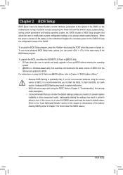
.... Refer to Chapter 5, "Troubleshooting," for how to boot. Chapter 2 BIOS Setup BIOS (Basic Input and Output System) records hardware parameters of the BIOS Setup program. To see more advanced BIOS Setup menu options, you not flash the BIOS. To upgrade the BIOS, use either the GIGABYTE Q-Flash or @BIOS utility. • Q-Flash allows the user to prevent system...
.... Refer to Chapter 5, "Troubleshooting," for how to boot. Chapter 2 BIOS Setup BIOS (Basic Input and Output System) records hardware parameters of the BIOS Setup program. To see more advanced BIOS Setup menu options, you not flash the BIOS. To upgrade the BIOS, use either the GIGABYTE Q-Flash or @BIOS utility. • Q-Flash allows the user to prevent system...

Manual
Page 32
... screen at system startup, refer to the instructions on the Full Screen LOGO Show item on BIOS Setup settings. Note: The setting in time. H67A-UD3H-B3 F5e . . . . : BIOS Setup : XpressRecovery2 : Boot Menu : Qflash 11/16/2010-H67-7A89UG06C-00 Function Keys SATA Mode Message: "SATA is... the first boot device setting as needed. : Q-FLASH Press the key to access the Q-Flash utility directly without entering BIOS Setup. To show the BIOS POST screen. BIOS Setup - 32 - 2-1 Startup Screen The following screens may appear when the computer boots. The LOGO Screen (Default) ...
... screen at system startup, refer to the instructions on the Full Screen LOGO Show item on BIOS Setup settings. Note: The setting in time. H67A-UD3H-B3 F5e . . . . : BIOS Setup : XpressRecovery2 : Boot Menu : Qflash 11/16/2010-H67-7A89UG06C-00 Function Keys SATA Mode Message: "SATA is... the first boot device setting as needed. : Q-FLASH Press the key to access the Q-Flash utility directly without entering BIOS Setup. To show the BIOS POST screen. BIOS Setup - 32 - 2-1 Startup Screen The following screens may appear when the computer boots. The LOGO Screen (Default) ...

Manual
Page 33
...press + to access more advanced options. • When the system is displayed on the bottom line of the Main Menu. Press to BIOS Load CMOS from BIOS Main Menu Help The on-screen description of a highlighted setup option is not stable as shown below) appears on the screen. Help for ...Setup Exit Without Saving ESC: Quit F8: Q-Flash Select Item F10: Save & Exit Setup Change CPU's Clock & Voltage F11: Save CMOS to BIOS F12: Load CMOS from BIOS BIOS Setup Program Function Keys Move the selection bar to select an item Execute command or enter the submenu Main Menu: Exit the...
...press + to access more advanced options. • When the system is displayed on the bottom line of the Main Menu. Press to BIOS Load CMOS from BIOS Main Menu Help The on-screen description of a highlighted setup option is not stable as shown below) appears on the screen. Help for ...Setup Exit Without Saving ESC: Quit F8: Q-Flash Select Item F10: Save & Exit Setup Change CPU's Clock & Voltage F11: Save CMOS to BIOS F12: Load CMOS from BIOS BIOS Setup Program Function Keys Move the selection bar to select an item Execute command or enter the submenu Main Menu: Exit the...

Manual
Page 34
...profiles (Profile 1-8) and name each profile. First enter the profile name (to erase the default profile name, use this function to load the BIOS settings from BIOS If your CPU, memory, etc. Standard CMOS Features Use this menu to configure the system time and date, hard drive types, and..., USB, integrated audio, and integrated LAN, etc. Power Management Setup Use this menu to configure all changes and the previous settings remain in BIOS Setup. Set User Password Change, set , or disable password. It allows you can use the SPACE key) and then press to complete....
...profiles (Profile 1-8) and name each profile. First enter the profile name (to erase the default profile name, use this function to load the BIOS settings from BIOS If your CPU, memory, etc. Standard CMOS Features Use this menu to configure the system time and date, hard drive types, and..., USB, integrated audio, and integrated LAN, etc. Power Management Setup Use this menu to configure all changes and the previous settings remain in BIOS Setup. Set User Password Change, set , or disable password. It allows you can use the SPACE key) and then press to complete....
Manual
Page 35
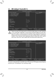
...Miscellaneous Settings [Press Enter] [Press Enter] [Press Enter] [Press Enter] [Press Enter] Item Help Menu Level BIOS Version BCLK CPU Frequency Memory Frequency Total Memory Size CPU Temperature Vcore DRAM Voltage F5e 99.80 MHz 3094.12 MHz 1332.... Settings [Press Enter] [Press Enter] [Press Enter] [Press Enter] [Press Enter] Item Help Menu Level BIOS Version BCLK CPU Frequency Memory Frequency Total Memory Size CPU Temperature Vcore DRAM Voltage F5e 99.80 MHz 3094.12 MHz 1332....
...Miscellaneous Settings [Press Enter] [Press Enter] [Press Enter] [Press Enter] [Press Enter] Item Help Menu Level BIOS Version BCLK CPU Frequency Memory Frequency Total Memory Size CPU Temperature Vcore DRAM Voltage F5e 99.80 MHz 3094.12 MHz 1332.... Settings [Press Enter] [Press Enter] [Press Enter] [Press Enter] [Press Enter] Item Help Menu Level BIOS Version BCLK CPU Frequency Memory Frequency Total Memory Size CPU Temperature Vcore DRAM Voltage F5e 99.80 MHz 3094.12 MHz 1332....

Manual
Page 36
For more information about Intel CPUs' unique features, please visit Intel's website. Current Status This screen provides information on the CPU being installed. BIOS Setup - 36 - CPU Frequency Displays the current operating CPU frequency. (Note) This item is dependent on CPU/memory frequencies/parameters. Advanced Frequency Settings CMOS ...
For more information about Intel CPUs' unique features, please visit Intel's website. Current Status This screen provides information on the CPU being installed. BIOS Setup - 36 - CPU Frequency Displays the current operating CPU frequency. (Note) This item is dependent on CPU/memory frequencies/parameters. Advanced Frequency Settings CMOS ...

Manual
Page 37
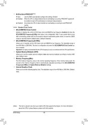
... core frequency to enable the Intel CPU Turbo Boost technology. For more enhanced power-saving state than C1. Auto lets the BIOS automatically configure this feature. When enabled, the CPU core frequency and voltage will automatically reduce the core frequency in order to ...or disables Intel CPU Enhanced Halt (C1E) function, a CPU power-saving function in system halt state. Auto lets the BIOS automatically configure this function. Auto lets the BIOS automatically configure this setting. (Default: Auto) C3/C6 State Support (Note) Allows you to determine whether to set a ...
... core frequency to enable the Intel CPU Turbo Boost technology. For more enhanced power-saving state than C1. Auto lets the BIOS automatically configure this feature. When enabled, the CPU core frequency and voltage will automatically reduce the core frequency in order to ...or disables Intel CPU Enhanced Halt (C1E) function, a CPU power-saving function in system halt state. Auto lets the BIOS automatically configure this function. Auto lets the BIOS automatically configure this setting. (Default: Auto) C3/C6 State Support (Note) Allows you to determine whether to set a ...
Manual
Page 38
... - Bi-Directional PROCHOT (Note) Auto Lets the BIOS automatically configure this feature. Disabled Only allows the CPU to detect whether an overheating is occurring, PROCHOT signals will allow for automated system reboot, or ...
... - Bi-Directional PROCHOT (Note) Auto Lets the BIOS automatically configure this feature. Disabled Only allows the CPU to detect whether an overheating is occurring, PROCHOT signals will allow for automated system reboot, or ...

Manual
Page 39
... Interleaving, Rank Interleaving, Channel A Timing Settings, and Channel B Timing Settings items to operate at three different performance levels. BIOS Setup Turbo Lets the system operate at its good performance level. (Default) Extreme Lets the system operate at its best performance...two items above are : Auto (default), Quick, Expert. Auto lets the BIOS automatically configure this setting. (Default: Auto) Rank Interleaving Enables or disables memory rank interleaving. Auto lets the BIOS automatically configure this setting. (Default: Auto) - 39 - Profile VTT ...
... Interleaving, Rank Interleaving, Channel A Timing Settings, and Channel B Timing Settings items to operate at three different performance levels. BIOS Setup Turbo Lets the system operate at its good performance level. (Default) Extreme Lets the system operate at its best performance...two items above are : Auto (default), Quick, Expert. Auto lets the BIOS automatically configure this setting. (Default: Auto) Rank Interleaving Enables or disables memory rank interleaving. Auto lets the BIOS automatically configure this setting. (Default: Auto) - 39 - Profile VTT ...


