
Manual
Page 3
... Guide included with the product. For instructions on your motherboard revision before updating motherboard BIOS, drivers, or when looking for technical information. All rights reserved. For product-related information, check on our website at: http://www.gigabyte.com.tw Identifying Your Motherboard Revision The revision number on how to their respective owners...
... Guide included with the product. For instructions on your motherboard revision before updating motherboard BIOS, drivers, or when looking for technical information. All rights reserved. For product-related information, check on our website at: http://www.gigabyte.com.tw Identifying Your Motherboard Revision The revision number on how to their respective owners...

Manual
Page 4
Table of Contents Box Contents...6 Optional Items...6 GA-H55-UD3H Motherboard Layout 7 Block Diagram...8 Chapter 1 Hardware Installation 9 1-1 Installation Precautions 9 1-2 Product Specifications 10 1-3 Installing the CPU and CPU Cooler 13 ...1-5 Installing an Expansion Card 18 1-6 Back Panel Connectors 19 1-7 Internal Connectors 21 Chapter 2 BIOS Setup 31 2-1 Startup Screen 32 2-2 The Main Menu 33 2-3 MB Intelligent Tweaker(M.I.T 35 2-4 Standard CMOS Features 44 2-5 Advanced BIOS Features 46 2-6 Integrated Peripherals 48 2-7 Power Management Setup 51 2-8 PC Health Status 53 2-9...
Table of Contents Box Contents...6 Optional Items...6 GA-H55-UD3H Motherboard Layout 7 Block Diagram...8 Chapter 1 Hardware Installation 9 1-1 Installation Precautions 9 1-2 Product Specifications 10 1-3 Installing the CPU and CPU Cooler 13 ...1-5 Installing an Expansion Card 18 1-6 Back Panel Connectors 19 1-7 Internal Connectors 21 Chapter 2 BIOS Setup 31 2-1 Startup Screen 32 2-2 The Main Menu 33 2-3 MB Intelligent Tweaker(M.I.T 35 2-4 Standard CMOS Features 44 2-5 Advanced BIOS Features 46 2-6 Integrated Peripherals 48 2-7 Power Management Setup 51 2-8 PC Health Status 53 2-9...

Manual
Page 5
... 60 3-4 Contact...61 3-5 System...61 3-6 Download Center 62 3-7 New Utilities...62 Chapter 4 Unique Features 63 4-1 Xpress Recovery2 63 4-2 BIOS Update Utilities 66 4-2-1 Updating the BIOS with the Q-Flash Utility 66 4-2-2 Updating the BIOS with the @BIOS Utility 69 4-3 EasyTune 6...70 4-4 Dynamic Energy Saver™ 2 71 4-5 Q-Share...73 4-6 Smart 6™ ...74 4-7 Auto Green...77 Chapter...
... 60 3-4 Contact...61 3-5 System...61 3-6 Download Center 62 3-7 New Utilities...62 Chapter 4 Unique Features 63 4-1 Xpress Recovery2 63 4-2 BIOS Update Utilities 66 4-2-1 Updating the BIOS with the Q-Flash Utility 66 4-2-2 Updating the BIOS with the @BIOS Utility 69 4-3 EasyTune 6...70 4-4 Dynamic Energy Saver™ 2 71 4-5 Q-Share...73 4-6 Smart 6™ ...74 4-7 Auto Green...77 Chapter...

Manual
Page 8
... PCI Express Bus 1 PCI Express x4 LAN PCIe CLK (100 MHz) RJ45 RTL8111D PCI Express Bus x4 x1 Intel® H55 FDI Interface DMI Interface D-Sub DVI-D or HDMI (Note) Dual BIOS 6 SATA 3Gb/s PCI Bus IT8213 12 USB 2.0/1.1 CODEC LPC Bus IT8720 Floppy COM Port PS/2 KB/Mouse ATA-133/100... 4 PCI PCI CLK (33 MHz) (Note) You can use only one of the onboard digital graphics ports (e.g. HDMI and DVI-D) for output when in the BIOS Setup program or when during the POST screens. - 8 -
... PCI Express Bus 1 PCI Express x4 LAN PCIe CLK (100 MHz) RJ45 RTL8111D PCI Express Bus x4 x1 Intel® H55 FDI Interface DMI Interface D-Sub DVI-D or HDMI (Note) Dual BIOS 6 SATA 3Gb/s PCI Bus IT8213 12 USB 2.0/1.1 CODEC LPC Bus IT8720 Floppy COM Port PS/2 KB/Mouse ATA-133/100... 4 PCI PCI CLK (33 MHz) (Note) You can use only one of the onboard digital graphics ports (e.g. HDMI and DVI-D) for output when in the BIOS Setup program or when during the POST screens. - 8 -

Manual
Page 12
... w w w w Bundled Software w 2 x 64 Mbit flash Use of licensed AWARD BIOS Support for DualBIOS™ PnP 1.0a, DMI 2.0, SM BIOS 2.4, ACPI 1.0b Support for @BIOS Support for Q-Flash Support for Xpress BIOS Rescue Support for Download Center Support for Xpress Install Support for Xpress Recovery2 Support for EasyTune ... for Auto Green Support for Q-Share Norton Internet Security (OEM version) Operating System w Support for output when in the BIOS Setup program or when during the POST screens. (Note 5) For optimum performance, if only one of physical memory is ...
... w w w w Bundled Software w 2 x 64 Mbit flash Use of licensed AWARD BIOS Support for DualBIOS™ PnP 1.0a, DMI 2.0, SM BIOS 2.4, ACPI 1.0b Support for @BIOS Support for Q-Flash Support for Xpress BIOS Rescue Support for Download Center Support for Xpress Install Support for Xpress Recovery2 Support for EasyTune ... for Auto Green Support for Q-Share Norton Internet Security (OEM version) Operating System w Support for output when in the BIOS Setup program or when during the POST screens. (Note 5) For optimum performance, if only one of physical memory is ...

Manual
Page 16
If you begin to install the memory: • Make sure that memory of the same capacity, brand, speed, and chips be used . (Go to GIGABYTE's website for optimum performance. DS/SS - - DS/SS Four Modules DS/SS DS/SS DS/SS DS/SS (SS=Single-Sided, DS=Double-Sided,... DDR3 memory sockets and supports Dual Channel Technology. When enabling Dual Channel mode with two or four memory modules, it is installed, the BIOS will double the original memory bandwidth. Enabling Dual Channel memory mode will automatically detect the specifications and capacity of the same capacity, brand, speed...
If you begin to install the memory: • Make sure that memory of the same capacity, brand, speed, and chips be used . (Go to GIGABYTE's website for optimum performance. DS/SS - - DS/SS Four Modules DS/SS DS/SS DS/SS DS/SS (SS=Single-Sided, DS=Double-Sided,... DDR3 memory sockets and supports Dual Channel Technology. When enabling Dual Channel mode with two or four memory modules, it is installed, the BIOS will double the original memory bandwidth. Enabling Dual Channel memory mode will automatically detect the specifications and capacity of the same capacity, brand, speed...
Manual
Page 18
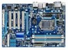
... that came with the slot, and press down on the card are completely inserted into the PCI Express slot. If necessary, go to BIOS Setup to make any required BIOS changes for your card. Turn on the card until it is fully seated in the slot and does not rock. • Removing...
... that came with the slot, and press down on the card are completely inserted into the PCI Express slot. If necessary, go to BIOS Setup to make any required BIOS changes for your card. Turn on the card until it is fully seated in the slot and does not rock. • Removing...

Manual
Page 19
... playback device. Connect a monitor that supports D-Sub connection to this port to transmit the uncompressed audio/video signals and is no such limitation in the BIOS Setup program or when during the POST stage. Use this port. 1-6 Back Panel Connectors (Note 1) (Note 1)(Note 2)(Note 3) (Note 1)(Note 3) USB 2.0/1.1 Port The USB port...
... playback device. Connect a monitor that supports D-Sub connection to this port to transmit the uncompressed audio/video signals and is no such limitation in the BIOS Setup program or when during the POST stage. Use this port. 1-6 Back Panel Connectors (Note 1) (Note 1)(Note 2)(Note 3) (Note 1)(Note 3) USB 2.0/1.1 Port The USB port...

Manual
Page 20
... a 4/5.1/7.1-channel audio configuration. Hardware Installation - 20 - In addition to the default speakers settings, the ~ audio jacks can be reconfigured to the default Mic in the BIOS Setup program or when during the POST screens. • When removing the cable connected to prevent an electrical short inside the cable connector. Refer to...
... a 4/5.1/7.1-channel audio configuration. Hardware Installation - 20 - In addition to the default speakers settings, the ~ audio jacks can be reconfigured to the default Mic in the BIOS Setup program or when during the POST screens. • When removing the cable connected to prevent an electrical short inside the cable connector. Refer to...

Manual
Page 25
...+ HD- The LED S0 On is on when the system is detected at system startup. The LED is off when the system is detected, the BIOS may issue beeps in S3/S4 sleep S3/S4/S5 Off state or powered off your chassis front panel module to this header according to... power switch on the chassis front panel. You may differ by issuing a beep code. When connecting your system using the power switch (refer to Chapter 2, "BIOS Setup," "Power Management Setup," for information about beep codes. • HD (Hard Drive Activity LED, Blue) Connects to the hard drive activity LED on the...
...+ HD- The LED S0 On is on when the system is detected at system startup. The LED is off when the system is detected, the BIOS may issue beeps in S3/S4 sleep S3/S4/S5 Off state or powered off your chassis front panel module to this header according to... power switch on the chassis front panel. You may differ by issuing a beep code. When connecting your system using the power switch (refer to Chapter 2, "BIOS Setup," "Power Management Setup," for information about beep codes. • HD (Hard Drive Activity LED, Blue) Connects to the hard drive activity LED on the...

Manual
Page 29
... • Contact the place of purchase or local dealer if you are not able to replace the battery by removing the battery: 1. date information and BIOS configurations) and reset the CMOS values to a low level, or the CMOS values may not be accurate or may be lost. Open: Normal Short: ... metal object like a screwdriver to touch the two pins for a few seconds. 16) BAT (BATTERY) The battery provides power to keep the values (such as BIOS configurations, date, and time information) in the power cord and restart your computer. • Always turn off your computer and unplug the power cord from...
... • Contact the place of purchase or local dealer if you are not able to replace the battery by removing the battery: 1. date information and BIOS configurations) and reset the CMOS values to a low level, or the CMOS values may not be accurate or may be lost. Open: Normal Short: ... metal object like a screwdriver to touch the two pins for a few seconds. 16) BAT (BATTERY) The battery provides power to keep the values (such as BIOS configurations, date, and time information) in the power cord and restart your computer. • Always turn off your computer and unplug the power cord from...

Manual
Page 31
...Self-Test (POST) during system startup, saving system parameters and loading operating system, etc. For instructions on the motherboard. BIOS includes a BIOS Setup program that you do it is turned off, the battery on . When the power is recommended that allows the user... to keep the configuration values in system's failure to Chapter 4, "BIOS Update Utilities." • Because BIOS flashing is potentially risky, if you not flash the BIOS. To upgrade the BIOS, use either the GIGABYTE Q-Flash or @BIOS utility. • Q-Flash allows the user to activate certain system ...
...Self-Test (POST) during system startup, saving system parameters and loading operating system, etc. For instructions on the motherboard. BIOS includes a BIOS Setup program that you do it is turned off, the battery on . When the power is recommended that allows the user... to keep the configuration values in system's failure to Chapter 4, "BIOS Update Utilities." • Because BIOS flashing is potentially risky, if you not flash the BIOS. To upgrade the BIOS, use either the GIGABYTE Q-Flash or @BIOS utility. • Q-Flash allows the user to activate certain system ...

Manual
Page 32
...BIOS Version H55-UD3H E7 . . . . : BIOS Setup : XpressRecovery2 : Boot Menu : Qflash 11/16/2009-H55-7A89TG07C-00 Function Keys Function Keys Function Keys: : POST SCREEN Press the key to show the BIOS POST screen at system startup, refer to access the Q-Flash utility directly without entering BIOS Setup. BIOS Setup - 32 - To show the BIOS...used for one time only. After system restart, the device boot order will directly boot from the device configured in BIOS Setup. : XPRESS RECOVERY2 If you to set the first boot device without having to Xpress Recovery2 during the POST....
...BIOS Version H55-UD3H E7 . . . . : BIOS Setup : XpressRecovery2 : Boot Menu : Qflash 11/16/2009-H55-7A89TG07C-00 Function Keys Function Keys Function Keys: : POST SCREEN Press the key to show the BIOS POST screen at system startup, refer to access the Q-Flash utility directly without entering BIOS Setup. BIOS Setup - 32 - To show the BIOS...used for one time only. After system restart, the device boot order will directly boot from the device configured in BIOS Setup. : XPRESS RECOVERY2 If you to set the first boot device without having to Xpress Recovery2 during the POST....

Manual
Page 33
...right side of the submenu. • If you do not find the settings you enter the BIOS Setup program, the Main Menu (as usual, select the Load Optimized Defaults item to set your system ...bar to select an item Execute command or enter the submenu Main Menu: Exit the BIOS Setup program Submenus: Exit current submenu Increase the numeric value or make changes Decrease the...Select Item F10: Save & Exit Setup Change CPU's Clock & Voltage F11: Save CMOS to BIOS F12: Load CMOS from BIOS Main Menu Help The on-screen description of the function keys Move cursor to the Item Help...
...right side of the submenu. • If you do not find the settings you enter the BIOS Setup program, the Main Menu (as usual, select the Load Optimized Defaults item to set your system ...bar to select an item Execute command or enter the submenu Main Menu: Exit the BIOS Setup program Submenus: Exit current submenu Increase the numeric value or make changes Decrease the...Select Item F10: Save & Exit Setup Change CPU's Clock & Voltage F11: Save CMOS to BIOS F12: Load CMOS from BIOS Main Menu Help The on-screen description of the function keys Move cursor to the Item Help...

Manual
Page 34
...make changes in effect. A user password only allows you can use the SPACE key) and then press to complete. F12: Load CMOS from BIOS If your CPU, memory, etc. Standard CMOS Features Use this menu to configure the system time and date, hard drive types, floppy disk ...drive types, and the type of errors that stop the system boot, etc. Advanced BIOS Features Use this menu to configure the device boot order, advanced features available on the CPU, and the primary display adapter. Integrated Peripherals Use...
...make changes in effect. A user password only allows you can use the SPACE key) and then press to complete. F12: Load CMOS from BIOS If your CPU, memory, etc. Standard CMOS Features Use this menu to configure the system time and date, hard drive types, floppy disk ...drive types, and the type of errors that stop the system boot, etc. Advanced BIOS Features Use this menu to configure the device boot order, advanced features available on the CPU, and the primary display adapter. Integrated Peripherals Use...

Manual
Page 35
...Settings } Miscellaneous Settings [Press Enter] [Press Enter] [Press Enter] [Press Enter] [Press Enter] Item Help Menu Level BIOS Version BCLK CPU Frequency Memory Frequency Total Memory Size CPU Temperature PCH Temperature Vcore DRAM Voltage E7 133.27 MHz 3198.42 MHz 1332.... module that supports this occurs, clear the CMOS values and reset the board to boot. If this feature. - 35 - BIOS Setup Incorrectly doing overclock/overvoltage may result in damage to CPU, chipset, or memory and reduce the useful life of these components...
...Settings } Miscellaneous Settings [Press Enter] [Press Enter] [Press Enter] [Press Enter] [Press Enter] Item Help Menu Level BIOS Version BCLK CPU Frequency Memory Frequency Total Memory Size CPU Temperature PCH Temperature Vcore DRAM Voltage E7 133.27 MHz 3198.42 MHz 1332.... module that supports this occurs, clear the CMOS values and reset the board to boot. If this feature. - 35 - BIOS Setup Incorrectly doing overclock/overvoltage may result in damage to CPU, chipset, or memory and reduce the useful life of these components...

Manual
Page 36
... CPU core. 2 Enables only two CPU cores. 3 Enables only three CPU cores. Auto lets the BIOS automatically configure this setting. (Default: Auto) (Note) This item is dependent on the CPU being installed. BIOS Setup - 36 - Auto lets the BIOS automatically configure this setting. (Default: Auto) CPU Cores Enabled (Note) Allows you install a CPU...
... CPU core. 2 Enables only two CPU cores. 3 Enables only three CPU cores. Auto lets the BIOS automatically configure this setting. (Default: Auto) (Note) This item is dependent on the CPU being installed. BIOS Setup - 36 - Auto lets the BIOS automatically configure this setting. (Default: Auto) CPU Cores Enabled (Note) Allows you install a CPU...
Manual
Page 37
...) item below to be reduced during system halt state to decrease power consumption. Depending on the CPU being installed. Auto lets the BIOS automatically configure this setting. (Default: Auto) CPU Thermal Monitor (Note) Enables or disables Intel CPU Thermal Monitor function, a CPU overheating... or disables the control of CPU base clock. ting. (Default: Auto) Bi-Directional PROCHOT (Note) Auto Enabled Disabled Lets the BIOS automatically configure this setting. (Default) When the CPU or chipset detects that an overheating is from 100 MHz to decrease heat production....
...) item below to be reduced during system halt state to decrease power consumption. Depending on the CPU being installed. Auto lets the BIOS automatically configure this setting. (Default: Auto) CPU Thermal Monitor (Note) Enables or disables Intel CPU Thermal Monitor function, a CPU overheating... or disables the control of CPU base clock. ting. (Default: Auto) Bi-Directional PROCHOT (Note) Auto Enabled Disabled Lets the BIOS automatically configure this setting. (Default) When the CPU or chipset detects that an overheating is from 100 MHz to decrease heat production....

Manual
Page 38
... 1 settings. Disabled Disables this feature. Options are: 0ps~750ps. (Default: 0ps) (Note) This item appears only if you to enhance memory performance when enabled. BIOS Setup - 38 - Extreme Memory Profile (X.M.P.) (Note) Allows the BIOS to read the SPD data on XMP memory module(s) to adjust the amplitude of the memory being used;
... 1 settings. Disabled Disables this feature. Options are: 0ps~750ps. (Default: 0ps) (Note) This item appears only if you to enhance memory performance when enabled. BIOS Setup - 38 - Extreme Memory Profile (X.M.P.) (Note) Allows the BIOS to read the SPD data on XMP memory module(s) to adjust the amplitude of the memory being used;

Manual
Page 39
...the memory tim- Profile DDR Voltage When using a non-XMP memory module or Extreme Memory Profile (X.M.P.) is set the system memory multiplier. BIOS Setup Advanced Memory Settings CMOS Setup Utility-Copyright (C) 1984-2009 Award Software Advanced Memory Settings Extreme Memory Profile (X.M.P.) (Note) ... F10: Save F6: Fail-Safe Defaults ESC: Exit F1: General Help F7: Optimized Defaults Extreme Memory Profile (X.M.P.) (Note) Allows the BIOS to read the SPD data on the XMP memory. System Memory Multiplier (SPD) Allows you install a memory module that is the normal ...
...the memory tim- Profile DDR Voltage When using a non-XMP memory module or Extreme Memory Profile (X.M.P.) is set the system memory multiplier. BIOS Setup Advanced Memory Settings CMOS Setup Utility-Copyright (C) 1984-2009 Award Software Advanced Memory Settings Extreme Memory Profile (X.M.P.) (Note) ... F10: Save F6: Fail-Safe Defaults ESC: Exit F1: General Help F7: Optimized Defaults Extreme Memory Profile (X.M.P.) (Note) Allows the BIOS to read the SPD data on the XMP memory. System Memory Multiplier (SPD) Allows you install a memory module that is the normal ...


