Manual
Page 1
GA-G31M-S2L/ GA-G31M-S2C LGA775 socket motherboard for Intel® CoreTM processor family/ Intel® Pentium® processor family/Intel® Celeron® processor family User's Manual Rev. 1103 12ME-G31MS2L-1103R
GA-G31M-S2L/ GA-G31M-S2C LGA775 socket motherboard for Intel® CoreTM processor family/ Intel® Pentium® processor family/Intel® Celeron® processor family User's Manual Rev. 1103 12ME-G31MS2L-1103R
Manual
Page 4
... The revision number on how to their respective owners. Example: All rights reserved. The trademarks mentioned in the use GIGABYTE's unique features, read the User's Manual. „ For instructions on your motherboard revision before updating motherboard BIOS, drivers, or when looking for technical information. Documentation Classifications In order to assist in this : "REV: X.X." Copyright...
... The revision number on how to their respective owners. Example: All rights reserved. The trademarks mentioned in the use GIGABYTE's unique features, read the User's Manual. „ For instructions on your motherboard revision before updating motherboard BIOS, drivers, or when looking for technical information. Documentation Classifications In order to assist in this : "REV: X.X." Copyright...
Manual
Page 7
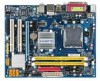
The box contents are for reference only. Box Contents GA-G31M-S2L or GA-G31M-S2C motherboard Motherboard driver disk User's Manual One IDE cable and one floppy disk drive cable Two SATA 3Gb/s cables I/O Shield • The box contents above are subject to change without notice. • The motherboard image is for reference only and the actual items shall depend on product package you obtain. Optional Items 2-port USB 2.0 bracket (Part No. 12CR1-1UB030-51R) 2-port SATA power cable (Part No. 12CF1-2SERPW-01R) S/PDIF out cable (Part No. 12CR1-1SPOUT-02R) - 7 -
The box contents are for reference only. Box Contents GA-G31M-S2L or GA-G31M-S2C motherboard Motherboard driver disk User's Manual One IDE cable and one floppy disk drive cable Two SATA 3Gb/s cables I/O Shield • The box contents above are subject to change without notice. • The motherboard image is for reference only and the actual items shall depend on product package you obtain. Optional Items 2-port USB 2.0 bracket (Part No. 12CR1-1UB030-51R) 2-port SATA power cable (Part No. 12CF1-2SERPW-01R) S/PDIF out cable (Part No. 12CR1-1SPOUT-02R) - 7 -
Manual
Page 11
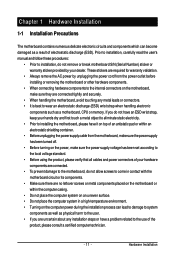
...or have a problem related to system components as well as a motherboard, CPU or memory. Hardware Installation If you do not have an ESD wrist strap, keep your dealer. Prior to installation, carefully read the user's manual and follow these procedures: • Prior to installation, do ...not allow screws to come in a high-temperature environment. • Turning on an uneven surface. • Do not place the computer system in contact with the motherboard circuit or its components. &#...
...or have a problem related to system components as well as a motherboard, CPU or memory. Hardware Installation If you do not have an ESD wrist strap, keep your dealer. Prior to installation, carefully read the user's manual and follow these procedures: • Prior to installation, do ...not allow screws to come in a high-temperature environment. • Turning on an uneven surface. • Do not place the computer system in contact with the motherboard circuit or its components. &#...
Manual
Page 17
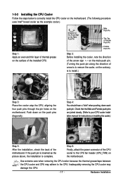
... and Female push pins are joined closely. (Refer to the CPU fan header (CPU_FAN) on the motherboard. Step 6: Finally, attach the power connector of the CPU cooler to your CPU cooler installation manual for instructions on installing the cooler.) Step 5: After the installation, check the back of arrow is ... Before installing the cooler, note the direction of the arrow sign on the male push pin. (Turning the push pin along the direction of the motherboard. Use extreme care when removing the CPU cooler because the thermal grease/tape between the CPU cooler and CPU may damage the CPU. - 17 - ...
... and Female push pins are joined closely. (Refer to the CPU fan header (CPU_FAN) on the motherboard. Step 6: Finally, attach the power connector of the CPU cooler to your CPU cooler installation manual for instructions on installing the cooler.) Step 5: After the installation, check the back of arrow is ... Before installing the cooler, note the direction of the arrow sign on the male push pin. (Turning the push pin along the direction of the motherboard. Use extreme care when removing the CPU cooler because the thermal grease/tape between the CPU cooler and CPU may damage the CPU. - 17 - ...
Manual
Page 20
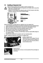
... PCI Express x16 Graphics Card: • Installing a Graphics Card: Gently push down on the card until it is securely seated in your computer. GA-G31M-S2L/S2C Motherboard - 20 - Locate an expansion slot that came with a screw. 5. Make sure the metal contacts on the top edge of the card until... changes for your expansion card in the slot. 3. Make sure the card is fully seated in the expansion slot. 1. Carefully read the manual that supports your expansion card. • Always turn off the computer and unplug the power cord from the chassis back panel. 2. After ...
... PCI Express x16 Graphics Card: • Installing a Graphics Card: Gently push down on the card until it is securely seated in your computer. GA-G31M-S2L/S2C Motherboard - 20 - Locate an expansion slot that came with a screw. 5. Make sure the metal contacts on the top edge of the card until... changes for your expansion card in the slot. 3. Make sure the card is fully seated in the expansion slot. 1. Carefully read the manual that supports your expansion card. • Always turn off the computer and unplug the power cord from the chassis back panel. 2. After ...
Manual
Page 31
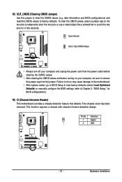
... the CMOS values to clear the CMOS values (e.g. Failure to do so may cause damage to the motherboard. • After system restart, go to BIOS Setup to load factory defaults (select Load Optimized Defaults) or manually configure the BIOS settings (refer to touch the two pins for BIOS configurations). 16) CI (Chassis...
... the CMOS values to clear the CMOS values (e.g. Failure to do so may cause damage to the motherboard. • After system restart, go to BIOS Setup to load factory defaults (select Load Optimized Defaults) or manually configure the BIOS settings (refer to touch the two pins for BIOS configurations). 16) CI (Chassis...
Manual
Page 38
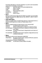
Head Number of extended memory. Floppy 3 Mode Support Allows you wish to enter the parameters manually, refer to the information on the system. No Errors The system boot will stop for an error during the POST. All, But Disk/Key The ... drive. All Errors Whenever the BIOS detects a non-fatal error the system boot will be reserved for any error. Base Memory Also called conventional memory. GA-G31M-S2L/S2C Motherboard - 38 -
Head Number of extended memory. Floppy 3 Mode Support Allows you wish to enter the parameters manually, refer to the information on the system. No Errors The system boot will stop for an error during the POST. All, But Disk/Key The ... drive. All Errors Whenever the BIOS detects a non-fatal error the system boot will be reserved for any error. Base Memory Also called conventional memory. GA-G31M-S2L/S2C Motherboard - 38 -
Manual
Page 42
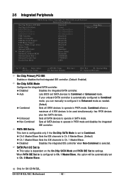
... allows a maximum of 4 ATA devices to be automatically set SATA devices to operate in SATA mode. GA-G31M-S2L/S2C Motherboard - 42 - Only for GA-G31M-S2L. If your onboard SATA controller is automatically configured to Combined mode, you can manually re-configure it to Enhanced mode as needed. (Default) Combined Sets all SATA devices to Combined or...
... allows a maximum of 4 ATA devices to be automatically set SATA devices to operate in SATA mode. GA-G31M-S2L/S2C Motherboard - 42 - Only for GA-G31M-S2L. If your onboard SATA controller is automatically configured to Combined mode, you can manually re-configure it to Enhanced mode as needed. (Default) Combined Sets all SATA devices to Combined or...
Manual
Page 50
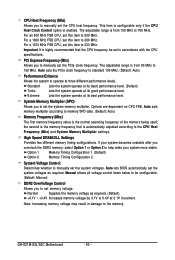
...Auto lets BIOS automatically set the system memory multiplier. Normal Supplies the memory voltage as required. If your system more stable. Manual allows all voltage control items below to be set the CPU host frequency. The adjustable range is from 90 MHz to the... System Voltage Control Determines whether to 200 MHz. For an 800 MHz FSB CPU, set this item to manually set memory voltage. The adjustable range is enabled. GA-G31M-S2L/S2C Motherboard - 50 - Note: Increasing memory voltage may result in accordance with the CPU specifications. Auto sets the ...
...Auto lets BIOS automatically set the system memory multiplier. Normal Supplies the memory voltage as required. If your system more stable. Manual allows all voltage control items below to be set the CPU host frequency. The adjustable range is from 90 MHz to the... System Voltage Control Determines whether to 200 MHz. For an 800 MHz FSB CPU, set this item to manually set memory voltage. The adjustable range is enabled. GA-G31M-S2L/S2C Motherboard - 50 - Note: Increasing memory voltage may result in accordance with the CPU specifications. Auto sets the ...
Manual
Page 57
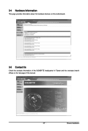
3-4 Hardware Information This page provides information about the hardware devices on this motherboard. 3-5 Contact Us Check the contacts information of the GIGABYTE headquarter in Taiwan and the overseas branch offices on the last page of this manual. - 57 - Drivers Installation
3-4 Hardware Information This page provides information about the hardware devices on this motherboard. 3-5 Contact Us Check the contacts information of the GIGABYTE headquarter in Taiwan and the overseas branch offices on the last page of this manual. - 57 - Drivers Installation
Manual
Page 68
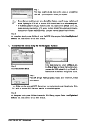
... save the BIOS update file (e.g. Step 3: Press OK to load BIOS defaults. 3. GA-G31M-S2L/S2C Motherboard - 68 - Step 3: First make sure the model name on the @BIOS server site, please manually download the BIOS update file from the Internet or through other source. Updating the BIOS with...the Open dialog box, select All Files (*.*) in an unbootable system. • If the BIOS update file for your motherboard model. g31ms2l.f1) obtained from GIGABYTE's website and follow the instructions in "Update the BIOS without Using the Internet Update Function Click Update New BIOS Step 1: ...
... save the BIOS update file (e.g. Step 3: Press OK to load BIOS defaults. 3. GA-G31M-S2L/S2C Motherboard - 68 - Step 3: First make sure the model name on the @BIOS server site, please manually download the BIOS update file from the Internet or through other source. Updating the BIOS with...the Open dialog box, select All Files (*.*) in an unbootable system. • If the BIOS update file for your motherboard model. g31ms2l.f1) obtained from GIGABYTE's website and follow the instructions in "Update the BIOS without Using the Internet Update Function Click Update New BIOS Step 1: ...
Manual
Page 82
..., collection, recycling and disposal of properly. GA-G31M-S2L/S2C Motherboard - 82 - Regulatory Statements Regulatory Notices This document must not be copied without notice and should be prosecuted. Restriction of Hazardous Substances (RoHS) Directive Statement GIGABYTE products have been carefully selected to add and... recycling of your waste equipment at the Customer Care number listed in your product's user's manual and we at the time of our natural resources, GIGABYTE provides the following information on its packaging, which indicates that the information in your "end of...
..., collection, recycling and disposal of properly. GA-G31M-S2L/S2C Motherboard - 82 - Regulatory Statements Regulatory Notices This document must not be copied without notice and should be prosecuted. Restriction of Hazardous Substances (RoHS) Directive Statement GIGABYTE products have been carefully selected to add and... recycling of your waste equipment at the Customer Care number listed in your product's user's manual and we at the time of our natural resources, GIGABYTE provides the following information on its packaging, which indicates that the information in your "end of...


