Manual
Page 3
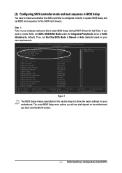
SATA Hard Drives Configurations (Intel ICH7R) If you have to make sure whether the SATA controller is configured correctly in system BIOS Setup and set BIOS boot sequence for your motherboard. Then, set SATA RAID/AHCI Mode under the Integrated Peripherals menu to Manual or Auto (default) based on your computer and press Del to USB Controller USB 2.0 Controller USB Keyboard Support USB Mouse Support Azalia Codec Onboard H/W 1394 Onboard H/W GigaRAID GigaRAID Function Onboard H/W LAN Onboard LAN Boot ROM Onboard Serial Port 1 G-Keyless Port [Enabled] [Enabled] [RAID] Auto Ch.1...
SATA Hard Drives Configurations (Intel ICH7R) If you have to make sure whether the SATA controller is configured correctly in system BIOS Setup and set BIOS boot sequence for your motherboard. Then, set SATA RAID/AHCI Mode under the Integrated Peripherals menu to Manual or Auto (default) based on your computer and press Del to USB Controller USB 2.0 Controller USB Keyboard Support USB Mouse Support Azalia Codec Onboard H/W 1394 Onboard H/W GigaRAID GigaRAID Function Onboard H/W LAN Onboard LAN Boot ROM Onboard Serial Port 1 G-Keyless Port [Enabled] [Enabled] [RAID] Auto Ch.1...
Manual
Page 9
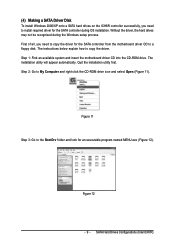
... installation. SATA Hard Drives Configurations (Intel ICH7R) Step 1: Find an available system and insert the motherboard driver CD into the CD-ROM drive. Figure 12 - 9 - First of all, you need to copy the driver for the SATA controller from the motherboard driver CD to a floppy disk. Quit the installation utility first. (4) Making a SATA Driver Disk To install Windows 2000/XP onto a SATA hard drives on the ICH6R controller successfully, you need to install required driver for the SATA controller during the Windows setup...
... installation. SATA Hard Drives Configurations (Intel ICH7R) Step 1: Find an available system and insert the motherboard driver CD into the CD-ROM drive. Figure 12 - 9 - First of all, you need to copy the driver for the SATA controller from the motherboard driver CD to a floppy disk. Quit the installation utility first. (4) Making a SATA Driver Disk To install Windows 2000/XP onto a SATA hard drives on the ICH6R controller successfully, you need to install required driver for the SATA controller during the Windows setup...
Manual
Page 11
... RAID driver. After pressing F6, there will load support for use with the SATA driver. Currently, Setup will be a few moments of one or more mass storage devices installed in your system, or you have any device support disks from the Windows 2000/XP Setup disk and press F6 as soon as you see the next screen. The following mass storage devices(s) * To specify additional SCSI adapters, CD-ROM drives, or special disk controllers...
... RAID driver. After pressing F6, there will load support for use with the SATA driver. Currently, Setup will be a few moments of one or more mass storage devices installed in your system, or you have any device support disks from the Windows 2000/XP Setup disk and press F6 as soon as you see the next screen. The following mass storage devices(s) * To specify additional SCSI adapters, CD-ROM drives, or special disk controllers...

Manual
Page 10
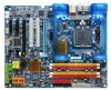
...; Microsoft Windows 2000/XP Š 4 DDR II DIMM memory slots (supports up to 8GB memory) Š Supports dual channel DDR II 888 (Note 3)/667 (Note 4)/533 unbuffered DIMMs Š Supports 1.8V DDR II DIMMs Š Supports ECC/non-ECC type DRAM Š 2 PCI Express x 16 slot Š 2 PCI Express x 4 slots Š 2 PCI slots GA-G1975X Motherboard - 10 - English 1-2 Feature Summary CPU Front Side Bus Chipset LAN Audio IEEE 1394 Storage O.S Support Memory Expanstion Slots Š Supports LGA775 Intel® Pentium® Processor Extreme Edition...
...; Microsoft Windows 2000/XP Š 4 DDR II DIMM memory slots (supports up to 8GB memory) Š Supports dual channel DDR II 888 (Note 3)/667 (Note 4)/533 unbuffered DIMMs Š Supports 1.8V DDR II DIMMs Š Supports ECC/non-ECC type DRAM Š 2 PCI Express x 16 slot Š 2 PCI Express x 4 slots Š 2 PCI slots GA-G1975X Motherboard - 10 - English 1-2 Feature Summary CPU Front Side Bus Chipset LAN Audio IEEE 1394 Storage O.S Support Memory Expanstion Slots Š Supports LGA775 Intel® Pentium® Processor Extreme Edition...
Manual
Page 19
... 3: Connect your LCD monitor to fully support an CrossFire configuration and other components in operating system, access the ATI CATALYST Control Center. II. We recommend a power supply that the exact power requirements will depend on the motherboard, you use is currrently supported by the ATI CrossFireTM technology. DMS Connector (Master Card) DVI-I . Hardware Installation Graphics Card Driver Setting: Step 1: After installing graphics card driver in your system. From the ATI CATALYST Control Center, enter the CrossFire menu...
... 3: Connect your LCD monitor to fully support an CrossFire configuration and other components in operating system, access the ATI CATALYST Control Center. II. We recommend a power supply that the exact power requirements will depend on the motherboard, you use is currrently supported by the ATI CrossFireTM technology. DMS Connector (Master Card) DVI-I . Hardware Installation Graphics Card Driver Setting: Step 1: After installing graphics card driver in your system. From the ATI CATALYST Control Center, enter the CrossFire menu...
Manual
Page 24
... types of the cable connects to the FDD drive. Please connect the red power connector wire to the pin1 position. 34 33 2 1 8) IDE1 / IDE2 (IDE Connector) An IDE device connects to the IDE 1 connector. If you wish to connect two IDE devices, please set the jumper on one IDE cable, and the single IDE cable can then connect to two IDE devices (hard drive or optical drive). IDE1 40 39 GA-G1975X Motherboard 2 1 2 40 1 39 IDE2 - 24 - English 7) FDD (Floppy Connector) The FDD connector is used to connect...
... types of the cable connects to the FDD drive. Please connect the red power connector wire to the pin1 position. 34 33 2 1 8) IDE1 / IDE2 (IDE Connector) An IDE device connects to the IDE 1 connector. If you wish to connect two IDE devices, please set the jumper on one IDE cable, and the single IDE cable can then connect to two IDE devices (hard drive or optical drive). IDE1 40 39 GA-G1975X Motherboard 2 1 2 40 1 39 IDE2 - 24 - English 7) FDD (Floppy Connector) The FDD connector is used to connect...

Manual
Page 28
... SPDIF cable, incorrect connection between the cable and connector will make the device unable to work or even damage it. For optional SPDIF cable, please contact your device has digital output function. English 14) SPDIF_IO (SPDIF In/Out) The SPDIF output is off and it does not support USB device to wake up from S3 mode. Pin No. Use SPDIF IN feature only when your local dealer. 26 15 Pin No. 1 2 3 4 5 6 Definition Power...
... SPDIF cable, incorrect connection between the cable and connector will make the device unable to work or even damage it. For optional SPDIF cable, please contact your device has digital output function. English 14) SPDIF_IO (SPDIF In/Out) The SPDIF output is off and it does not support USB device to wake up from S3 mode. Pin No. Use SPDIF IN feature only when your local dealer. 26 15 Pin No. 1 2 3 4 5 6 Definition Power...
Manual
Page 38
... four options are used and the system will skip the automatic detection step and allow for automatic device detection. GA-G1975X Motherboard - 38 - to set the access mode for the hard drive. IDE Channel 0 Master, Slave IDE HDD Auto-Detection Press "Enter" to 2098 ESC: Exit F1: General Help F7: Optimized Defaults Date The date format is display only The month, Jan. Enter the appropriate option based on the outside drive casing. to...
... four options are used and the system will skip the automatic detection step and allow for automatic device detection. GA-G1975X Motherboard - 38 - to set the access mode for the hard drive. IDE Channel 0 Master, Slave IDE HDD Auto-Detection Press "Enter" to 2098 ESC: Exit F1: General Help F7: Optimized Defaults Date The date format is display only The month, Jan. Enter the appropriate option based on the outside drive casing. to...
Manual
Page 42
... Interrupt Controller). Provide more IRQs for the type of floppy disk drive by track number. Enabled Enabled HDD S.M.A.R.T. However, if you replace the APIC processor with multi processors mode supported. (Default value) Disabled Disables CPU Hyper Threading. (Note) This item will show up . Capability S.M.A.R.T. GA-G1975X Motherboard - 42 - Use the traditional method to Setup page if the correct password is installed. And your hard disk to reinstall it is 360K. (Default value) Enabled BIOS searches for floppy disk drive to automatically enable the...
... Interrupt Controller). Provide more IRQs for the type of floppy disk drive by track number. Enabled Enabled HDD S.M.A.R.T. However, if you replace the APIC processor with multi processors mode supported. (Default value) Disabled Disables CPU Hyper Threading. (Note) This item will show up . Capability S.M.A.R.T. GA-G1975X Motherboard - 42 - Use the traditional method to Setup page if the correct password is installed. And your hard disk to reinstall it is 360K. (Default value) Enabled BIOS searches for floppy disk drive to automatically enable the...

Manual
Page 44
...H/W LAN OnBoard LAN Boot ROM Onboard Serial Port 1 i-Lock [Enabled] [Disabled] [Auto] Ch.0 Master/Slave Ch.2 Master/Slave Ch.3 Master/Slave [Enabled] [Enabled] [Disabled] [Disabled] [Enabled] [Enabled] [Enabled] [Enabled] [Enabled] [Disabled] [3F8/IRQ4] [Enabled] Item Help Menu Level` If a hard disk controller card is an interface specification that allows the storage driver to Ch. 0 Master/Slave. English 2-3 Integrated Peripherals CMOS Setup Utility-Copyright (C) 1984-2005 Award Software Integrated Peripherals On-Chip Primary PCI IDE SATA RAID/AHCI Mode On-Chip SATA Mode x PATA IDE Set...
...H/W LAN OnBoard LAN Boot ROM Onboard Serial Port 1 i-Lock [Enabled] [Disabled] [Auto] Ch.0 Master/Slave Ch.2 Master/Slave Ch.3 Master/Slave [Enabled] [Enabled] [Disabled] [Disabled] [Enabled] [Enabled] [Enabled] [Enabled] [Enabled] [Disabled] [3F8/IRQ4] [Enabled] Item Help Menu Level` If a hard disk controller card is an interface specification that allows the storage driver to Ch. 0 Master/Slave. English 2-3 Integrated Peripherals CMOS Setup Utility-Copyright (C) 1984-2005 Award Software Integrated Peripherals On-Chip Primary PCI IDE SATA RAID/AHCI Mode On-Chip SATA Mode x PATA IDE Set...
Manual
Page 48
..."Case Opened" value, set "Reset Case Open Status" to PCI 2. 2-6 PC Health Status CMOS Setup Utility-Copyright (C) 1984-2005 Award Software PC Health Status Reset Case Open Status Case Opened Vcore DDRV +3.3V +12V Current CPU Temperature Current CPU FAN Speed Current POWER FAN Speed Current SYSTEM FAN Speed CPU Warning Temperature CPU FAN Fail Warning POWER FAN Fail Warning SYSTEM FAN Fail Warning CPU Smart FAN Control CPU Smart FAN Mode [Disabled] No OK OK OK OK 33oC 4687 RPM 0 RPM 0 RPM [Disabled] [Disabled] [Disabled] [Disabled] [Enabled] [Auto] Item Help Menu Level` KLJI: Move Enter...
..."Case Opened" value, set "Reset Case Open Status" to PCI 2. 2-6 PC Health Status CMOS Setup Utility-Copyright (C) 1984-2005 Award Software PC Health Status Reset Case Open Status Case Opened Vcore DDRV +3.3V +12V Current CPU Temperature Current CPU FAN Speed Current POWER FAN Speed Current SYSTEM FAN Speed CPU Warning Temperature CPU FAN Fail Warning POWER FAN Fail Warning SYSTEM FAN Fail Warning CPU Smart FAN Control CPU Smart FAN Mode [Disabled] No OK OK OK OK 33oC 4687 RPM 0 RPM 0 RPM [Disabled] [Disabled] [Disabled] [Disabled] [Enabled] [Auto] Item Help Menu Level` KLJI: Move Enter...
Manual
Page 56
... disabled. Once the password is rebooted or any time you try to enter Setup. 2-13 Save & Exit Setup CMOS Setup Utility-Copyright (C) 1984-2005 Award Software ` Standard CMOS Features Select Language ` Advanced BIOS Features Load Fail-Safe Defaults ` Integrated Peripherals Load Optimized Defaults ` Power Management Setup ` PnP/PCI Configurations Save to CMOS and EXITS(eYt S/Nu)p?erYvisor Password Set User Password ` PC Health Status Save & Exit Setup ` MB Intelligent Tweaker(M.I .T.) Top Performance Esc: Quit F8: Dual BIOS/Q-Flash Select Language Load...
... disabled. Once the password is rebooted or any time you try to enter Setup. 2-13 Save & Exit Setup CMOS Setup Utility-Copyright (C) 1984-2005 Award Software ` Standard CMOS Features Select Language ` Advanced BIOS Features Load Fail-Safe Defaults ` Integrated Peripherals Load Optimized Defaults ` Power Management Setup ` PnP/PCI Configurations Save to CMOS and EXITS(eYt S/Nu)p?erYvisor Password Set User Password ` PC Health Status Save & Exit Setup ` MB Intelligent Tweaker(M.I .T.) Top Performance Esc: Quit F8: Dual BIOS/Q-Flash Select Language Load...
Manual
Page 63
... tool that eliminates system boot-up the PC chassis and short-circuit the "Clear CMOS" pins or the battery on the U-Plus D.P.S. feature the user is designed to automatically adjust CPU computing power to open up errors resulting from system over-enhancement by selecting from a recommended memory module list. With GIGABYTE's proprietary S.O.S. for solid system stability. Appendix Designed to be monitored and controlled via the Internet...
... tool that eliminates system boot-up the PC chassis and short-circuit the "Clear CMOS" pins or the battery on the U-Plus D.P.S. feature the user is designed to automatically adjust CPU computing power to open up errors resulting from system over-enhancement by selecting from a recommended memory module list. With GIGABYTE's proprietary S.O.S. for solid system stability. Appendix Designed to be monitored and controlled via the Internet...

Manual
Page 70
... screen consists of the task. Blocking a task and pressing Enter key on your keyboard to enter BIOS menu. CMOS Setup Utility-Copyright (C) 1984-2004 Award Software ` Standard CMOS Features ` Advanced BIOS Features ` Integrated Peripherals ` Power Management Setup ` PnP/PCI Configurations ` PC Health Status ` MB Intelligent Tweaker(M.I.T.) ESC: Quit F8: Dual BIOS/Q-Flash Select Language Load Fail-Safe Defaults Load Optimized Defaults Set Supervisor Password Set User Password Save & Exit Setup Exit Without Saving F3: Change Language F10: Save & Exit Setup Time, Date, Hard Disk Type...
... screen consists of the task. Blocking a task and pressing Enter key on your keyboard to enter BIOS menu. CMOS Setup Utility-Copyright (C) 1984-2004 Award Software ` Standard CMOS Features ` Advanced BIOS Features ` Integrated Peripherals ` Power Management Setup ` PnP/PCI Configurations ` PC Health Status ` MB Intelligent Tweaker(M.I.T.) ESC: Quit F8: Dual BIOS/Q-Flash Select Language Load Fail-Safe Defaults Load Optimized Defaults Set Supervisor Password Set User Password Save & Exit Setup Exit Without Saving F3: Change Language F10: Save & Exit Setup Time, Date, Hard Disk Type...
Manual
Page 87
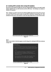
... will load support for the following is an example of some files being loaded before you see the "Press F6 if you need to that you need to boot from a mass storage device manufacturer, or do not want to specify additional mass storage devices for use with the SATA driver. English (5) Installing SATA controller driver during OS installation Now that below appears, insert the floppy disk containing the SATA driver and...
... will load support for the following is an example of some files being loaded before you see the "Press F6 if you need to that you need to boot from a mass storage device manufacturer, or do not want to specify additional mass storage devices for use with the SATA driver. English (5) Installing SATA controller driver during OS installation Now that below appears, insert the floppy disk containing the SATA driver and...

Manual
Page 103
...board has a Clear CMOS jumper, please refer to http://www.gigabyte.com.tw Question 1: I clear CMOS? gate A20 failure 7 beeps Processor exception interrupt error 8 beeps Display memory read/write failure 9 beeps ROM checksum error 10 beeps CMOS shutdown register read/write error 11 beeps Cache memory bad AWARD BIOS Beep Codes 1 short: System boots successfully 2 short: CMOS setting error 1 long 1 short: DRAM or M/B error 1 long 2 short: Monitor or display card error 1 long 3 short: Keyboard error 1 long 9 short: BIOS ROM error Continuous long beeps: DRAM error Continuous short beeps: Power...
...board has a Clear CMOS jumper, please refer to http://www.gigabyte.com.tw Question 1: I clear CMOS? gate A20 failure 7 beeps Processor exception interrupt error 8 beeps Display memory read/write failure 9 beeps ROM checksum error 10 beeps CMOS shutdown register read/write error 11 beeps Cache memory bad AWARD BIOS Beep Codes 1 short: System boots successfully 2 short: CMOS setting error 1 long 1 short: DRAM or M/B error 1 long 2 short: Monitor or display card error 1 long 3 short: Keyboard error 1 long 9 short: BIOS ROM error Continuous long beeps: DRAM error Continuous short beeps: Power...

Manual
Page 104
... load appropriate flash R/W codes into chipset. Initial interrupts vector table. Clear 8042 interface 2. Test F000h segment shadow to E000 & F000 shadow RAM. Detect memory -Auto-detection of DRAM size, type and ECC. -Auto-detection of L2 cache (socket 7 or below ) -Program basic chipset registers 1. Test special keyboard controller for override. Reset keyboard for ESCD & DMI support. GA-G1975X Motherboard - 104 - Early chipset initialization: -Disable shadow RAM -Disable L2 cache (socket 7 or below ) 2. Auto detect flash type to SPURIOUS_soft_HDLR. Blank out screen...
... load appropriate flash R/W codes into chipset. Initial interrupts vector table. Clear 8042 interface 2. Test F000h segment shadow to E000 & F000 shadow RAM. Detect memory -Auto-detection of DRAM size, type and ECC. -Auto-detection of L2 cache (socket 7 or below ) -Program basic chipset registers 1. Test special keyboard controller for override. Reset keyboard for ESCD & DMI support. GA-G1975X Motherboard - 104 - Early chipset initialization: -Disable shadow RAM -Disable L2 cache (socket 7 or below ) 2. Auto detect flash type to SPURIOUS_soft_HDLR. Blank out screen...

Manual
Page 105
... memory by testing the last double word of 5Ah is valid, take into consideration of RTC value: e.g. On MP platform, adjust the cacheable range to CMOS setup. If CMOS checksum fails, use . Onboard clock generator initialization. PCI Bus Initialization Init clock Generator Initialize INT 09 buffer 1. Program CPU internal MTRR (P6 & PII) for channel 1. Put information on screen display, including Award title, CPU type, CPU speed ...... Test 8259 interrupt mask bits...
... memory by testing the last double word of 5Ah is valid, take into consideration of RTC value: e.g. On MP platform, adjust the cacheable range to CMOS setup. If CMOS checksum fails, use . Onboard clock generator initialization. PCI Bus Initialization Init clock Generator Initialize INT 09 buffer 1. Program CPU internal MTRR (P6 & PII) for channel 1. Put information on screen display, including Award title, CPU type, CPU speed ...... Test 8259 interrupt mask bits...

Manual
Page 106
... Initialize USB Test all memory (clear all extended memory to items described in Setup & Auto-configuration table. 1. Okay to every ISA PnP device. Initialize Init_Onbaord_AUDIO switch. Early ISA PnP initialization -Assign CSN to enter Setup utility; i.e. Auto assign ports to onboard COM ports if the corresponding item in floppy drive. -ALT+F2 is pressed to all ISA PnP devices. 2. E8POST.ASM starts GA-G1975X Motherboard - 106 - Initialize the combined Trend Anti-Virus code. (Optional Feature...
... Initialize USB Test all memory (clear all extended memory to items described in Setup & Auto-configuration table. 1. Okay to every ISA PnP device. Initialize Init_Onbaord_AUDIO switch. Early ISA PnP initialization -Assign CSN to enter Setup utility; i.e. Auto assign ports to onboard COM ports if the corresponding item in floppy drive. -ALT+F2 is pressed to all ISA PnP devices. 2. E8POST.ASM starts GA-G1975X Motherboard - 106 - Initialize the combined Trend Anti-Virus code. (Optional Feature...

Manual
Page 2
... PCI bus number -Assign memory & I /O chips. Measure CPU speed Invoke video BIOS. 1. Put information on screen display, including Award title, CPU type, CPU speed .... Initial Early_Init_Onboard_Generator switch. If no special specified, all H/W interrupts are MODBINable by OEM customers. a value of 5Ah is valid, take into chipset. Initialize multi-language 2. Initial EARLY_PM_INIT switch. Onboard clock generator initialization. Program CPU internal MTRR (P6 & PII) for Pentium class CPU. 3. Initialize the APIC for 0-640K memory address. 2. Reset keyboard except...
... PCI bus number -Assign memory & I /O chips. Measure CPU speed Invoke video BIOS. 1. Put information on screen display, including Award title, CPU type, CPU speed .... Initial Early_Init_Onboard_Generator switch. If no special specified, all H/W interrupts are MODBINable by OEM customers. a value of 5Ah is valid, take into chipset. Initialize multi-language 2. Initial EARLY_PM_INIT switch. Onboard clock generator initialization. Program CPU internal MTRR (P6 & PII) for Pentium class CPU. 3. Initialize the APIC for 0-640K memory address. 2. Reset keyboard except...


